Table of Contents
Advertisement
Quick Links
LME49600 Headphone
Amplifier Evaluation Board
User's Guide
Quick Start Guide
Apply a ±2.5V to ±17V power supply's voltage to the respec-
tive "V
+
", "GND" and "V
-
" pins on JU19
Apply a stereo audio signal to the RCA jacks J1 (Right) and
J2 (Left) or jumpers JU1 (Right) and JU17 (Left), observing
the signal input pin and the ground (GND) pin. Though not
typically installed, a stereo signal can also be applied to head-
phone jack HPJ1.
Connect a load to JU14 (Left) and another load to JU15
(Right), observing the signal output pin and the ground (GND)
pin. The stereo signal output is also available on the 1/8"
stereo headphone jack located in the board's "OUTPUT" sec-
tion
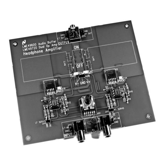
FIGURE 1. The LME49600/LME49720 Stereo Headphone Amplifier Demonstration Board
© 2008 National Semiconductor Corporation
National Semiconductor
Application Note 1768
Kevin Hoskins
February 29, 2008
Use VR1 to control the output signal amplitude.
Apply power. Make measurements. Plug in a pair of head-
phones. Enjoy.
Introduction
To help the user investigate and evaluate the LME49600's
performance and capabilities, a fully populated demonstration
board was created. Please contact the National Semiconduc-
tor Corporation's Audio Products Group for availability. This
board is shown in Figure 1. Connected to an external power
supply (±2.5V to ±17V ) and a signal source. The LME49600
demonstration board easily demonstrates the amplifier's fea-
tures.
300473
30047312
www.national.com
Advertisement
Table of Contents

Related Manuals for National Semiconductor LME49600


Summary of Contents for National Semiconductor LME49600
-
Page 1: Quick Start Guide
Figure 1. Connected to an external power (Right), observing the signal output pin and the ground (GND) supply (±2.5V to ±17V ) and a signal source. The LME49600 pin. The stereo signal output is also available on the 1/8”... -
Page 2: General Description
General Description Operating Conditions ■ ≤ ≤ The LME49600 is a high performance, low distortion high fi- Temperature Range –40°C 85°C delity 250mA audio buffer. Whereas there are many uses for ■ Amplifier Power the LME49600, this application note describes a headphone ≤... -
Page 3: Pcb Layout Guidelines
LME49600 demonstration board. The func- Connections tions of the different headers, 1/8” headphone jacks and RCA Connecting to the world is accomplished through a combina- jacks are detailed in Table 1. tion of RCA jacks, 1/8” stereo headphone jacks and 0.100”... -
Page 4: Bill Of Materials
1/4W resistor ±1% 1/4W YAGEO 1MΩ R9 – R12 1/4W, Axial MFR-25FBF-1M00 SWITCH SLIDE DPDT DPDT [Not Installed] National Semiconductor Corp. LME49720NA (Can also use U1, U2 LME49720NA LM4562, LME49860) (LM4562NA or LME49860NA) National Semiconductor Corp. U3, U4 LME49600 LME49600TS PANASONIC Dual gauged potentiometer 10kΩ... - Page 5 Demonstration Board PCB Layout Figure 5 is the bottom layer. Figure 6 is the bottom silkscreen Figures 3 through 6 show the different layers used to create layer. the LME49600 demonstration board. Figure 3 is the 30047316 Figure 3. Top Silkscreen 30047315 Figure 4.
- Page 6 30047313 Figure 5. Bottom Layer 30047314 Figure 6. Bottom Silk Layer www.national.com...
-
Page 7: Typical Performance
30047360 FIGURE 8: THD+N vs Output Power FIGURE 7: THD+N vs Output Power LME49720/LME49600 headphone amplifier LME49720/LME49600 headphone amplifier into (from top to bottom at 10mW): 16Ω, 32Ω, 64Ω, 300Ω into (from top to bottom at 0.1mW): 16Ω, 32Ω, 64Ω, 300Ω... - Page 8 30047363 14: THD+N vs Output Power FIGURE 13: THD+N vs Output Power LME49720/LME49600 headphone amplifier LME49720/LME49600 headphone amplifier into (from top to bottom at 20mW): 16Ω, 32Ω, 64Ω, 300Ω into (from top to bottom at 0.1mW): 16Ω, 32Ω, 64Ω, 300Ω...
-
Page 9: Revision History
Revision History Date Description 02/29/08 Initial release. www.national.com... - Page 10 Notes For more National Semiconductor product information and proven design tools, visit the following Web sites at: Products Design Support Amplifiers www.national.com/amplifiers WEBENCH www.national.com/webench Audio www.national.com/audio Analog University www.national.com/AU Clock Conditioners www.national.com/timing App Notes www.national.com/appnotes Data Converters www.national.com/adc Distributors www.national.com/contacts Displays www.national.com/displays...
Need help?
Do you have a question about the LME49600 and is the answer not in the manual?
Questions and answers