
Related Manuals for National Semiconductor LMH1983


Summary of Contents for National Semiconductor LMH1983
- Page 1 LMH1983 Evaluation Kit Users Guide LMH1983 Evaluation Kit Users Guide Version 1.0 2/4/10 Page 1 of 25...
- Page 2 National Semiconductor’s Analog Launch Pad (ALP) software graphical user interface (GUI). The GUI with the LMH1983 profile runs on Windows PC and can be used to program the device’s control registers through the I C interface. The Serial Peripheral Adapter (SPA)
-
Page 3: Applying Power To The Board
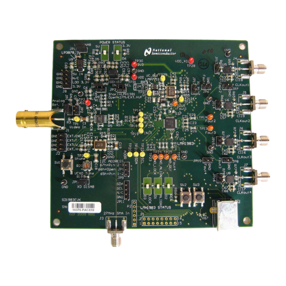
LMH1983 Evaluation Kit Users Guide LMH1983 EVALUATION BOARD OVERVIEW The following block diagram shows an overview of the LMH1983 evaluation board and general location of the main features, which will be discussed in the following sections of this manual. Power... -
Page 4: Installing The Software
LMH1983 Evaluation Kit Users Guide Installing the software: The evaluation kit contains a CD which has the control software on it. Running the program on the CD will install the software on your computer. Apply power to the Evaluation Board, and then attach a USB cable between the computer and the board. - Page 5 LMH1983 Evaluation Kit Users Guide Select “Install from a list or specific location” Page 5 of 25...
- Page 6 LMH1983 Evaluation Kit Users Guide Page 6 of 25...
- Page 7 The computer will warn you that the software has not passed Windows Logo Testing. Go ahead and Continue Anyway. The driver for the LMH1983 evaluation board will now be installed, and you can start the ALP software. When you start the Analog LaunchPAD software, it should recognize the evaluation board and the screen will look like the figure below.
- Page 8 There are several panels in the GUI - the first is the main control panel and allows for basic control over the board. Also very useful is the Registers tab, which will allow for detailed manipulation of the various registers in the LMH1983. Page 8 of 25...
- Page 9 C address select jumper JP9 (3-way) can be configured as follows to select one of the three I C slave addresses offered by the LMH1983. The default for the board, and for the ALP software is address ‘66h which corresponds to no jumper installed.
- Page 10 The GUI will display what format is being detected under the PLL1 For a comprehensive list of formats that can be detected, please refer to the LMH1983 datasheet. To determine format, the device measures the period of the Hsync input by counting 27MHz clock pulses over several Hsync periods.
- Page 11 LMH1983 Evaluation Kit Users Guide Page 11 of 25...
-
Page 12: Loop Filter
The external loop filter and 27 MHz VCXO are essential to the performance of PLL1, which dominates the overall loop response of the LMH1983. The loop response of PLL1 is influenced by the external loop components and can be characterized by its loop bandwidth and damping factor. - Page 13 The VCXO input control voltage input can be measured at TP29 (VC_BUF). Note that when the LMH1983 is operating in free run mode, the VC_LPF output set by the user-defined free run voltage control register may be limited by the output voltage range of the LMP7711, as it is not a rail-to-rail op amp.
- Page 14 27 MHz via the SMA clock input, J3. Either one of the options can be used as long as it’s not being used to drive the Hin reference of the LMH1983. To make use of this option, populate R21 and R28, then to use the on board oscillator, enable it by removing the jumper on JP5, and to use the external SMA, disable the oscillator with a jumper on JP5 and provide the reference on J3.
- Page 15 LMH1983 Evaluation Kit Users Guide Appendix A Schematics Page 15 of 25...
- Page 16 All labels should be present on top and bottom silk Layout Note: On Fout* pins and pins 11, 12, 13, 0.1uF screen (except for ICs). place direct components as close to LMH1983 as TP12 TP13 TP14 TP15 possible.
- Page 17 0 ohm (10nF) Designed for: PRJ_Customer Mod. Date: 11/3/2009 National Semiconductor and/or its licensors do not warrant the accuracy or completeness of Project: PRJ_Title this specification or any information contained therein. National and/or its licensors do not Sheet Title: Output...
- Page 18 HSYNC_B MUX ENAB shorts can be installed to VSYNC_B OPEN directly connect the HVF OPEN "EXT H" (inline w/ pin 5) signals to the LMH1983 inputs. COM1 Note: "GND" (inline w/ pins 1-4) VSYNC_A Short = Enable HSYNC_B COM4 Open = Hi-Z...
- Page 19 0.01uF 0.01uF 10uF 10uF 10uF 10uF 10uF 10uF 10uF Layout Note: Distribute caps around the 4 sides of VDD_CLK1 VDD_PLL34 LMH1983 for decoupling the VDD power supply plane. 250mA 250mA 220 ohm 220 ohm C100 C101 C102 C103 C104 0.01uF 0.01uF...
- Page 20 C112 535-9103-1-ND PE6 (INT.6/AIN.0) 0.1uF 16 MHz XTAL Osc. XTAL2 XTAL1 AT90USB128/64 C113 C114 C115 15pF 15pF 0.22uF Title RESET Interface LMH1983 Eval Board - USB Interface Size Number Revision Date: 11/3/2009 Sheet of File: C:\Projects\..\USB Interface.SchDoc Drawn By: Sauerwald...
Need help?
Do you have a question about the LMH1983 and is the answer not in the manual?
Questions and answers