
Subscribe to Our Youtube Channel
Related Manuals for National Semiconductor LM64


Summary of Contents for National Semiconductor LM64
- Page 1 LM64 Evaluation Board User’s Guide Copyright 2003 National Semiconductor Corporation...
-
Page 2: Table Of Contents
3.0 Connection Details......... . . 7 4.0 Schematic of LM64 Evaluation Board ......8, 9... -
Page 3: Introduction
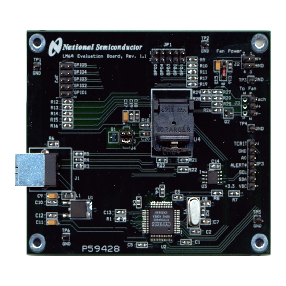
3. Jumpers to use for testing the GPD or GPIO pins if desired. The LM64 Evaluation Board, as shown in Figure 1 (without the socket lid for clarity), is a complete PCBA (printed circuit board assembly). The board has a USB connector, a voltage regulator circuit, a microcontroller, an EEPROM, and a LM64 Remote Diode Temperature Sensor with Integrated Fan Control. -
Page 4: Getting Started
A pair of wires from the power supply to a female header connector to connect with J2, Fan Power input, is suggested. If it is desired to run the software only, without the LM64 Evaluation board, omit items 2 and 3 and proceed to paragraph 2.3. -
Page 5: Test Setup - Hardware
(+5 or +12 VDC). Turn the power supply off. 2. Connect the power supply to the LM64 Evaluation Board jack J2 as shown in Figure 2. Make sure that the positive terminal is connected to V+ and the negative terminal is connected to the GND of J2. -
Page 6: Test Setup - System
2.0 Getting Started (continued) 2.5 Test Setup – System For proper fan control follow the following procedure, using SensorEval as described in the SensorEval software manual. IMPORTANT! Registers 4A, 4B, 4D and then either 4C (PWM Value) or the Lookup Table in Registers 4F through 5F must be programmed in that order for the initial fan control setup. -
Page 7: Connection Details
(left vertical row of pins). TCRIT and ALERT# are the open drain LM64 output pins. A0, the LM64 input address pin, can be manually jumpered to the GND pin to test the A0 function. VDC (+3.3 VDC), and the SMBus Clock and Data signals are available to the user for system monitoring. - Page 8 SHELL_2 Tach In TACH IN (Page 2) CY7C64603-52NC Tach In PC3/INT1# + 3.3 VDC TCRIT PC4/T0 Alert# CLKOUT PC5/T1 PC6/WR# AT24C02-10SI-2.7 PC7/RD# PA4/FWR# 1.5K 1.5K 0.1uF PA5/FRD# PB7/T2OUT PC0/RxD0 PC1/TxD0 Figure 5a. LM64 Evaluation Board Schematic, Page 1 of 2...
-
Page 9: Schematic Of Lm64 Evaluation Board
+ 3.3 VDC ALERT# TACH Tach In ALERT# HEADER 2x2 2.2 nF 1.5 k 1.5 k 1.5 k TCRIT HEADER 1X7 Alert# Alert# TCRIT TCRIT + 3.3 VDC MMBT2222A/SOT Figure 5b. Schematic of LM64 Evaluation Board – Page 2 of 2... -
Page 10: Bill Of Materials
5.0 LM64 Evaluation Board - Bill of Materials Item Quantity Reference Part ______________________________________________ C1,C2,C3,C4,C5,C6,C10, Capacitor, ceramic,0.1uF C12,C13,C14 C7,C8 Capacitor, ceramic,33pF C9,C11, C15, C17 Capacitor, ceramic,2.2uF C16, C18 Capacitor, ceramic,.01 uF Capacitor, ceramic,100 pF Capacitor, ceramic,2.2 nF Zener Diode ZMM5247/17V JP1,JP2... -
Page 11: Important Notice
IMPORTANT NOTICE Texas Instruments Incorporated and its subsidiaries (TI) reserve the right to make corrections, modifications, enhancements, improvements, and other changes to its products and services at any time and to discontinue any product or service without notice. Customers should obtain the latest relevant information before placing orders and should verify that such information is current and complete.
Need help?
Do you have a question about the LM64 and is the answer not in the manual?
Questions and answers