Table of Contents
Advertisement
Quick Links
Dec. 19, 2007
National Semiconductor
Rev - 1.0
CMC
Evaluation Board User's Guide
DAC121C08XEB, DAC101C08XEB, DAC081C08XEB
Micro Power Digital-to-Analog Converter (DAC)
2
with an I
C-Compatible Interface
12-bit
10-bit
8-bit
DAC121C085/
DAC101C085/
DAC081C085/
DAC121C081
DAC101C081
DAC081C081
1
http://www.national.com
Advertisement
Table of Contents

Related Manuals for National Semiconductor DAC121C085


Summary of Contents for National Semiconductor DAC121C085
- Page 1 Dec. 19, 2007 National Semiconductor Rev - 1.0 Evaluation Board User's Guide DAC121C08XEB, DAC101C08XEB, DAC081C08XEB Micro Power Digital-to-Analog Converter (DAC) with an I C-Compatible Interface 12-bit 10-bit 8-bit DAC121C085/ DAC101C085/ DAC081C085/ DAC121C081 DAC101C081 DAC081C081 http://www.national.com...
-
Page 2: Table Of Contents
Table of Contents 1.0 Introduction ......................3 2.0 Board Assembly....................4 3.0 Quick Start ......................4 3.1 Stand-Alone Mode..................4 3.2 Computer Mode..................5 4.0 Functional Description................... 6 4.1 Jumper Settings ..................6 4.2 I C Interface ....................6 4.3 DAC Reference Circuitry ................6 4.4 Analog Output ................... -
Page 3: Introduction
MSOP-8 version of the DAC. For the 12-bit required to evaluate this part with the WV4 resolution, the DAC121C085 is used. For the 10- Evaluation System. bit resolution, the DAC101C085 is used. For the 8-bit resolution, the DAC081C085 is used. All the... -
Page 4: Board Assembly
DAC121C08XEB board. Ground the middle add a 2kΩ resistive load. See Table 1 for terminal and connect +5V to the bottom jumper configurations. terminal closest to JP9. 8. The DAC121C085 will respond to I C address 2. Make following required jumper 0x0C by default with pins A0 and A1 floating. -
Page 5: Computer Mode
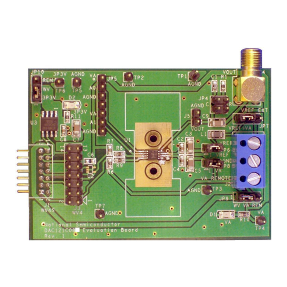
3.2 Computer Mode Refer to Figure 1 for locations of test points and +3.3V major components. The board comes configured for “plug-and-play” WaveVision evaluation. 1. Run the WaveVision 4 program, version 4.4 or (EEPROM) (EEPROM) higher is required to interface to the WV4 board. -
Page 6: Functional Description
C interface is driven by Load Select (See Below) the WaveVision4 board. The WaveVision4 software allows the user to drive the DAC121C085 C Address Select (See Below) with various digitized signals. Refer to Section 5.0 “Software Operation and Settings” for further Enable V supply to the DAC. -
Page 7: Analog Output
The majority of this current is for powering devices external to If you wish to use the local supply from the the DAC121C085 such as the pull-up resistors WaveVision4 Board, place a jumper across pins 1 and the LED. -
Page 8: Software Operation And Settings
7. Configure the I C address of the DAC. The 5.0 Software Operation and Settings DAC121C085 will respond to I C address The WaveVision4 software is included with the 0x0C by default with pins A0 and A1 floating WaveVision4 board and the latest version can be (no jumpers on JP5). -
Page 9: Evaluation Board Specifications
10. Configure the digital waveform to be 6.0 Evaluation Board Specifications converted by the DAC as seen in Figure 11. Board Size: 2.8" x 2.0" (7.2 cm x 5.1 cm) Please see the WaveVision4 User’s Manual Power Requirements Min: +2.7V , 6mA Max: +5.5V, 16mA for detailed instructions. -
Page 10: Hardware Schematic
7.0 Hardware Schematic Figure 12: DAC121C08XEB Evaluation Board Schematic http://www.national.com... -
Page 11: Evaluation Board Bill Of Materials
S5803-21-ND WV4S ED120-3 Digikey ED1609-ND berg2x7p Digikey A26529-40-ND VOUT hdr1x2 Digikey S1011E-36-ND 1206 Digikey 445-1543-1-ND 100uH rc0603 R6,R7 rc0603 R10,R11 rc0603 R8,R9 rc0603 TP1,TP2,TP3,TP5,TP7 tp_60c40dp Digikey S1011E-36-ND AGND tp_60c40dp Digikey S1011E-36-ND tp_60c40dp Digikey S1011E-36-ND 3P3V_REMOTE mso8SD-8 DAC121C085 sc70-5 24C02 http://www.national.com... -
Page 12: A1.0 Summary Tables Of Test Points, Jumpers, And Connectors
APPENDIX A1.0 Summary Tables of Test Points, Jumpers, and Connectors Test Points on the DAC121C08XEB Evaluation Board TP1: AGND Ground. Located at the top center of the board. TP2: AGND Ground. Located at the top center of the board. TP3: AGND Ground. - Page 13 [Blank Page] http://www.national.com...
- Page 14 European EMC Directive 89/336/EEC, or for compliance with any other electromagnetic compatibility requirements. National Semiconductor Corporation does not assume any responsibility for use of any circuitry or software supplied or described. No circuit patent licenses are implied.
-
Page 15: Important Notice
IMPORTANT NOTICE Texas Instruments Incorporated and its subsidiaries (TI) reserve the right to make corrections, modifications, enhancements, improvements, and other changes to its products and services at any time and to discontinue any product or service without notice. Customers should obtain the latest relevant information before placing orders and should verify that such information is current and complete. - Page 16 Mouser Electronics Authorized Distributor Click to View Pricing, Inventory, Delivery & Lifecycle Information: Texas Instruments DAC101C08XEB/NOPB DAC081C08XEB/NOPB...