Summary of Contents for National Semiconductor ADC12V170
- Page 1 Evaluation Board User’s Guide for ADC12V170: 12-Bit, 170 MSPS Analog to Digital Converter with LVDS Outputs www.national.com Rev 0.0 October 2007...
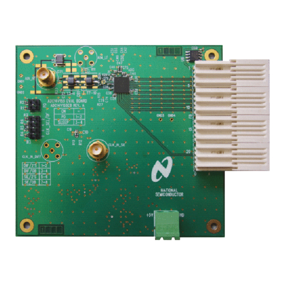
- Page 2 Jumper CLK_SEL/DF Clock Jumper Buffer (Reverse Side) Single- Ended Clock Input Figure 1. ADC12V170 Evaluation Board Connector and Jumper Locations ADC12V170 Evaluation Board User’s Guide < 150 MHz Analog Input Network 5.0V Power Connector - 2 - FutureBus Connector www.national.com...
-
Page 3: Board Assembly
ADC12V170 Evaluation Board User’s Guide The location and description of the components on the ADC12V170 evaluation board can be found in Figure 1 as well as Section 5.0 (Schematic) and Section 7.0 (Bill of Materials) of this user’s guide. -
Page 4: Functional Description
ADC by filtering the broadband noise of the signal generator. Data shown in the ADC12V170 datasheet was taken with a tunable bandpass filter made by Trilithic in the analog signal path. - Page 5 Figure 2. Analog Input Network of ADC12V170LFEB: F Figure 3. Analog Input Network of ADC12V170HFEB: F 4.3 ADC Reference and Input Common Mode The internal 1.0V reference on the ADC12V170 is used to acquire all of the results in the ADC12V170 datasheet.
- Page 6 Power to the ADC12V170 evaluation board is supplied through the green power connector labeled “+5V” which is located along the bottom edge of the board. Voltage and current requirements are: • +5V capable of providing up to 500mA (ADC12V170 evaluation board only) - 6 - The over- www.national.com...
-
Page 7: Evaluation Board Schematic
ADC12V170 Evaluation Board User’s Guide 5.0 Evaluation Board Schematic Figure 4. Signals www.national.com - 7 - Rev 0.0... - Page 8 ADC12V170 Evaluation Board User’s Guide 5.0 Schematic (cont.) Figure 5. Power Distribution www.national.com - 8 - Rev 0.0...
-
Page 9: Evaluation Board Layout
ADC12V170 Evaluation Board User’s Guide 6.0 Evaluation Board Layout Figure 6. Layer 1 - Signal www.national.com - 9 - Rev 0.0... - Page 10 ADC12V170 Evaluation Board User’s Guide 6.0 Evaluation Board Layout (cont.) Figure 7. Layer 2 - Ground www.national.com - 10 - Rev 0.0...
- Page 11 ADC12V170 Evaluation Board User’s Guide 6.0 Evaluation Board Layout (cont.) Figure 8. Layer 3 - Power www.national.com - 11 - Rev 0.0...
- Page 12 ADC12V170 Evaluation Board User’s Guide 6.0 Evaluation Board Layout (cont.) Figure 9. Layer 4 - Signal www.national.com - 12 - Rev 0.0...
- Page 13 Kemet sm/c_3216 Kemet Kemet sm/c_7343 Panasonic -ECG Samtec Samtec Samtec FCI Electronic SOT-223 National Semiconductor SOIC NARROW -8 National Semiconductor Phoenix Contact Phoenix Contact Fairchild Semiconductor 1806 Murata Electronics sm/r_0402 Vishay Dale sm/r_0402 Panasonic - ECG sm/r_0402 Yageo Corporation Vishay Dale...
- Page 14 Kemet sm/c_3216 Kemet sm/c_7343 Kemet Panasonic -ECG Samtec Samtec Samtec FCI Electronic SOT-223 National Semiconductor SOIC NARROW -8 National Semiconductor Phoenix Contact Phoenix Contact Fairchild Semiconductor 1806 Murata Electronics sm/r_0402 Vishay Dale sm/r_0402 Panasonic - ECG sm/r_0402 Yageo Corporation sm/r_0402...
-
Page 15: Life Support Policy
English Email: support@nsc.com National does not assume any responsibility for any circuitry described, no circuit patent licenses are implied and National reserves the right at any time without notice to change said circuitry and specifications. ADC12V170 Evaluation Board User’s Guide...


Need help?
Do you have a question about the ADC12V170 and is the answer not in the manual?
Questions and answers