Table of Contents
Advertisement
Quick Links
Installation & Operation Manual
®
tekmarNet
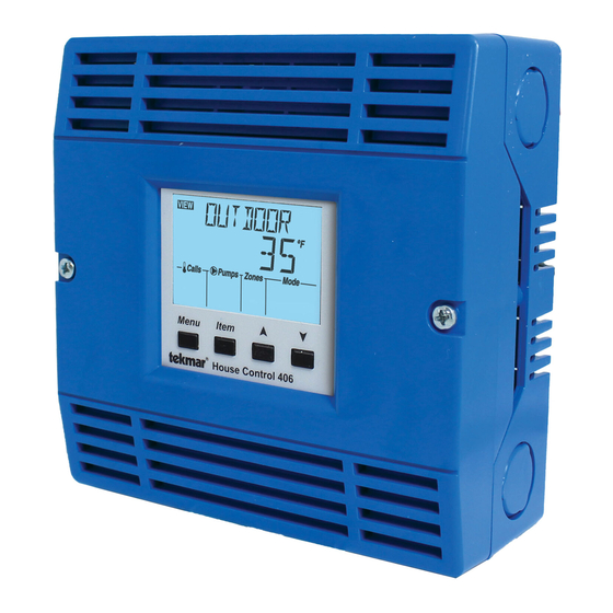
2 House Control 406
Introduction
The tN2 House Control 406 is designed to operate the
equipment in a 2-pipe, single tank, hydronic heating and
cooling system. It operates two heat pump stages (water-
to-water or air-to-water) with a backup heat source (boiler
or electric resistance). The heat pump provides either hot
or chilled water to a storage tank loop and optional mixed
temperature loop. For radiant heating, the water temperature
is calculated using outdoor temperature reset. For radiant
cooling, the chilled water temperature is maintained at an
adjustable setpoint, or is adjusted using dew-point reset with
a humidity sensor. A backup boiler can provide an outdoor
reset water temperature as well as domestic hot water and
setpoint water temperatures. The 406 operates 4 on-board
heating and cooling zones and is expandable up to 52 zones
total on the boiler, tank, and mix water temperatures.
Menu
House Control 406
Item
Features
•
One or two-stage heat pump control
•
Equal runtime rotation for two heat pumps
•
On/off or modulating boiler control
•
Tank, mix and boiler outdoor reset temperatures
•
Domestic hot water operation
•
Setpoint operation
•
Mixing with variable speed pump
•
For use with tekmarNet
•
Four 24 V (ac) built in powered zone valve outputs
•
Expand to 24 zones on two water temperatures using
tekmarNet
®
4 expansion ports
•
CSA C US Certified for use in USA and Canada
Benefi ts
•
Energy efficiency through Outdoor Temperature Reset
with Indoor Temperature Feedback
•
Indoor Temperature Feedback minimizes the water
temperature (increasing energy savings), and the ef-
ficiency of your mechanical equipment through inte-
grated tekmarNet
•
Zone Synchronization reduces equipment cycling
•
Auto Differential - Reduces boiler cycling
•
Compact enclosure for flexible installation
•
Simple zone expansion using Wiring Centers
Note
•
For hydronic cooling with a fancoil, use tekmarNet® 2
thermostat 530 or tekmarNet® 4 thermostat 540 with a
date code of December 2011 or newer.
•
For floor cooling, use tekmarNet® 2 thermostats 527,
528, 529, 530 or tekmarNet® 4 thermostats 537, 538, and
540 with a date code of December 2011 or newer.
1 of 48
Alternative
Replaces: New
Energy
®
2 Thermostats
®
Thermostats
© 2011
D 406
12/11
D 406 - 12/11
Advertisement
Table of Contents

Related Manuals for Tekmar tekmarNet 2 House Control 406


Summary of Contents for Tekmar tekmarNet 2 House Control 406
- Page 1 Installation & Operation Manual D 406 ® 12/11 tekmarNet 2 House Control 406 Alternative Replaces: New Energy Introduction The tN2 House Control 406 is designed to operate the equipment in a 2-pipe, single tank, hydronic heating and Features cooling system. It operates two heat pump stages (water- to-water or air-to-water) with a backup heat source (boiler •...
-
Page 2: Table Of Contents
Materials Required ------------------- ---------- ------------------------------------------------ -- ------ ------------------------------------------------------------------------------------- • (2) #10 x 1” Wood Screws • tekmar 009K (24 V (ac) transformer with 4” x 4” junction box) • (5) Wire Nuts • 4” x 4” Extension Ring for Electrical Junction Box •... -
Page 3: Physical Dimensions
Power Required - -- - - ------------------ --------- -------- -- -- -- -- -- -- -- -- ---- ---- ---- -- -- -- -- ---- -- --- --- - - - - - --- -- -- -- --- -- -- -- -- --- -- -- -- -- --- -- -- -- --- -- -- -- -- --- -- -- -- -- -- --- -- -- ------------ •... -
Page 4: Sizing The Transformer
The total power capacity of the power supply should be larger than the total load of all the devices connected to the control. This When adding up the loads, consider the following: total load must not exceed 100 VA. Multiple tekmar Transformer ® •... - Page 5 Figure 3 - Connect Neutral Wires Figure 5 - System Pumps (Left) for Power Source 2 Tank System Pump Mix System Pump Boil System Pump Pump HP Loop Transfer Pump Pump Variable Speed Pump Power Source 2 Figure 6 - System Pumps (Right) Figure 4 - Line Voltage Mix System Pump...
- Page 6 ® Wiring Center. fuse be used in order to protect the transformer from high currents. The tekmar Transformer 009 includes a fuse. • Connect the Tank terminals, tN4 and C, on the 406 to the corresponding tN4 and C Expansion terminals on the ex- •...
-
Page 7: Sensor Wiring
Wiring the Heat Pump On/Off Boiler The 406 can operate a single heat pump with a two-stage • Connect the Backup terminals on the 406 to the T-T (or R- compressor in heating or cooling mode. W) terminals on the boiler. •... -
Page 8: Testing The Sensor Wiring
Mounting the Universal Sensor ----------------------- ------------- ------------------------------- -- --- - ------------------------------------------------------------------------- Note: These sensors are designed to mount on a pipe or in a temperature immersion well. The Universal Sensor should be placed downstream of a pump or after an elbow or similar fitting. -
Page 9: Testing The Control Wiring
Testing the Zone Output -- -- -- -- ---- -- --- -- - -- -- -- -- -- -- -- -------------- If a fault is suspected, contact your tekmar sales representative Activate the User Test sequence and pause at Step 1 by pressing for assistance. -
Page 10: Max Heat
Testing the HP Loop Pump ---------------------- ---------------------- Testing the DHW Pump -------------------------- -------------------------- Activate the User Test sequence and pause at Step 10 by Activate the User Test sequence and pause at Step 16 by pressing the Item button once the HP Loop pump turns on. pressing the Item button once the DHW pump turns on. -
Page 11: Applications
Applications Mechanical A406-1 Description: The House Control 406 operates a two stage air source heat pump in heating or cooling mode to supply an outdoor reset water temperature to 4 on board tank temperature zones. Additional zones can be added using the Tank tN4 and C Expansion terminals. - Page 12 Electrical A406-1 ® tekmarNet 2 Thermostats tN2 tN2 tN2 tN2 tN2 tN2 tN2 tN2 DHW Sensor (S5) Y2 O Two Stage Air to Water Tank Sensor (S4) Heat Pump Mix/DHW tN2 tN2 tN2 tN2 tN2 tN2 tN2 tN2 Rc1 Y1 O/B No Power Zone 1 Zone 2...
- Page 13 Mechanical A406-2 Description: The House Control 406 operates two air source heat pumps in heating or cooling mode to supply an outdoor reset water temperature to 4 on board mix temperature zones and 4 tank zones connected to the Tank expansion terminals with a Wiring Center 314.
- Page 14 Electrical A406-2 Air to Water Heat Pumps tekmarNet ® 2 Thermostats tN2 tN2 tN2 tN2 tN2 tN2 tN2 tN2 Mix Sensor (S5) Tank Sensor (S4) Boiler Sensor (S4) Mix/DHW tN2 tN2 tN2 tN2 tN2 tN2 tN2 tN2 Rc1 Y1 O/B No Power Zone 1 Zone 2...
- Page 15 Mechanical A406-3 Description: The House Control 406 operates a water source heat pump in heating or cooling mode to supply an outdoor reset water temperature to 4 on board tank temperature zones. The 406 also operates a modulating condensing boiler to supply an outdoor reset water temperature to 4 boiler zones connected to the Boil expansion terminals with a Wiring Center 313.
- Page 16 Electrical A406-3 ® tekmarNet 2 Thermostats DHW Sensor (S5) tN2 tN2 tN2 tN2 tN2 tN2 tN2 tN2 Water-to Water Tank Sensor (S4) Heat Pump Boiler Sensor (S3) Mix/DHW tN2 tN2 tN2 tN2 tN2 tN2 tN2 tN2 Rc1 Y1 O/B No Power Zone 1 Zone 2 Zone 3...
- Page 17 Mechanical A406-4 Description: The House Control 406 operates a two stage water source heat pump in heating or cooling mode to supply an outdoor reset water temperature to 4 on board tank temperature zones. The 406 also operates an on/off boiler to supply an outdoor reset water temperature to 4 boiler zones connected to the Boil expansion terminals with a Wiring Center 314.
- Page 18 Electrical A406-4 tekmarNet ® 2 Thermostats tN2 tN2 tN2 tN2 tN2 tN2 tN2 tN2 DHW Sensor (S5) Y2 O Two Stage Tank Sensor (S4) Water to Water Heat Pump Boiler Sensor (S3) Mix/DHW tN2 tN2 tN2 tN2 tN2 tN2 tN2 tN2 Rc1 Y1 O/B No Power Zone 1 Zone 2...
- Page 19 Mechanical A406-5 Description: The House Control 406 operates two water source heat pumps in heating or cooling mode to supply an outdoor reset water temperature to 4 on board mix temperature zones and 4 tank zones connected to the Tank expansion terminals with a Wiring Center 313.
- Page 20 Electrical A406-5 Two Water to Water Heat Pumps tekmarNet ® 2 Thermostats tN2 tN2 tN2 tN2 tN2 tN2 tN2 tN2 Mix Sensor (S5) Tank Sensor (S4) Boiler Sensor (S3) Mix/DHW tN2 tN2 tN2 tN2 tN2 tN2 tN2 tN2 Rc1 Y1 O/B No Power Zone 1 Zone 2...
-
Page 21: User Interface
User Interface Display Item Field Menu Field Displays the name of the selected item Displays the current menu Number Field Status Fields Displays the current value of Displays the current status the selected item of the control’s inputs, outputs and operation. Most symbols in the status field are only visible when the VIEW Menu is selected... -
Page 22: Access Levels And Thermostat Lock
Item Button - - - - - - - - -- ----------------- ----- ----------------------------------------------------- --- -- -- - - - - - - - - - - -------------------------------- -------------------------------------------------- Each menu contains a list of Items that can be viewed and, in •... - Page 23 View Menu (2 of 3) Item Field Range Description BOILER MODULATION SECTION G Current percent modulation of the boiler’s burner. The boiler modulation increases when the boiler supply is less than the boiler target. The boiler modulation 0-100% decreases when the boiler supply is greater than the boiler target. Note: This item is only available when the BOIL TYPE setting is set to 0-10 or 4-20.
-
Page 24: Adjust Menu
View Menu (3 of 3) Item Field Range Description PRECOOL TANK The heat pump is cooling the storage tank while the zones remain off. This may continue for up to 30 minutes and then the zones are allowed to call for cooling. PURGING COOL Cool water is being purged from the storage tank and the heat pump is not allowed to come on. - Page 25 0-10 - 0-10 V (dc) modulating boiler EMS1, 4-20 - 4-20 mA modulating boiler EMS2 EMS1 - tekmar boiler staging controls Default = 1STG EMS2 - Viessmann modulating boilers Access: Installer Note: This item is only available when a boil water temperatures have been Set to: selected.
- Page 26 Adjust Menu (3 of 6) Item Field Range Description BOILER DESIGN SECTION D The supply water temperature required for the boiler zones to heat the building on the typical coldest day of the year. Recommendations: 70 to 200°F • High mass radiant floor = 120°F (50°C) (21 to 93.5°C) •...
- Page 27 Adjust Menu (4 of 6) Item Field Range Description 35 to 70°F (4 to 21°C) COOL SETPOINT SECTION D Default = 50°F Tank setpoint that will be maintained when in cooling mode (not for floor (10°C) cooling). Access: Installer Set to: ON, OFF DEW POINT SECTION C...
- Page 28 Adjust Menu (5 of 6) Item Field Range Description 30 to 70°F (1 to 21°C) HP RETURN MIN SECTION E Default = 40°F Prevents the heat pump from operating in cooling mode if the heat pump return (4.5°C) temperature falls below this setting. Access: Installer Set to: OFF, -10 to 60°F...
-
Page 29: Monitor Menu
Adjust Menu (6 of 6) Item Field Range Description 70 to 180°F (21 to 82°C) Default = 125°F DHW OCCUPIED SECTION F (51.5°C) If DHW Selects the temperature of the indirect DHW tank when DHW MODE = 1-4. MODE = 1-4 Selects the temperature of the DHW pre-heat tank when DHW MODE = 5. - Page 30 Monitor Menu (2 of 2) Item Field Range Description RUN TIME (AUXILIARY) 0 to 9999 Hours The total ‘on’ time of the Backup relay since the item was last reset. Press and Default = 0 hr hold the Up and Down buttons while viewing to reset. Access: Installer Note: Item is only available when BACKUP = AUX.
-
Page 31: Toolbox Menu
Toolbox Menu (1 of 1) The Toolbox Menu is a location for system information and Test functions. If any errors are present on the system, they will be located at the beginning of this menu. Item Field Range Description USER TEST ON or OFF Begins the test routine which tests the main control’s functions. -
Page 32: Sequence Of Operation
Sequence of Operation tekmarNet ® System Section A tekmarNet ® is a family of products that use communication to • Wiring Centers 313, 314, 315, 316 - Add additional zones operate the HVAC system in a comfortable and efficient manner. •... - Page 33 EMS1 The Mod dc/mA output uses 0-10 V (dc) to communicate a desired boiler target water temperature to a tekmar stager that accepts an EMS signal. 1 V (dc) corresponds to 50°F (10°C) and 10 V (dc) corresponds to 210°F (99°C).
-
Page 34: Heat Cool Operation
Heat Cool Operation Section C Mode - ----- - ---- - - - --------- --------------------- - ------------- - - - --------------------------- the words “PURGING HEAT” or “PURGING COOL” will be displayed in the view menu depending if the tank is currently There are five different modes that the heat pump and backup in the heat or cool mode. -
Page 35: Hydronic Operation
Without Humidity Sensor At the thermostat, floor cooling will stop when the room tem- perature cools to the heating target plus 3°F (1.5°C). Floor cooling may be performed without a humidity sensor. This operation is only recommended in dry areas where Floor Cooling Target humidity is not a concern. -
Page 36: Heat Pump Operation
Boiler Minimum Protection ---------------------- ---------------------- Note: The Variable Speed Pump does not provide boiler minimum protections when the BOIL TYPE is set to EMS1 or EMS2. When operating a non-condensing boiler, it is important to prevent cool water from returning to the boiler. Cold return Maximum Targets -------------------- ---- -- - -- -- ------------------------------- water temperatures create flue gas condensation, which if left... -
Page 37: Dhw Operation
• B = Heat pump normally operates in cool mode. Energize Outdoor Air Temperature Limit -- -- -- --- -- -- -- --- -- -- -- ------------ B to operate the heat pump in heat mode Heating - For AIR Source Heat Pumps Only At low outdoor air temperatures, it may not be economical to keep an air source heat pump operating during heating due to low COP. - Page 38 DHW MODE 1 - DHW in Parallel no Priority DHW MODE 4 - DHW in Primary / Secondary with Priority When a DHW Call is present, the DHW Pump is activated. When a DHW Call is present, the DHW Pump and the Boiler The Boiler System Pump does not turn on, but may operate System Pump are operated.
-
Page 39: Boiler Operation
DHW Priority Override ------------------- ---- ---- - -- --- -- -- -- -- --- -- --- -- -- - DHW Post Purge - -- -- ---- -- -- -- --- -- --- - -- -- -- -- - -- -- -- -- -- --- -- -- -- ------------ To prevent the building from cooling off too much or the pos- After the DHW Call is removed, the control performs a purge sibility of a potential freeze up during DHW priority, the control... - Page 40 Modulating Boiler Operation -------------------- -------------------- Boiler Motor Speed --------------------- -- -- -- -- - ------------------------------ The 406 can operate a single hot-water modulating boiler The Motor Speed is the amount of time the boiler requires to using the Mod dc/mA output and the Backup contact. Not all boilers require the use of the Backup contact.
-
Page 41: Setpoint Operation
Boiler Modulation Delay ------------------------- -- -- -- -- -- -- --- -- -- -- -- -- For 4-20 mA: The modulation delay is determined by the boiler manufacturer. Minimum Modulation = It is the amount of time that the burner must operate before Boiler’s Minimum Input Signal - 4mA x 100% the internal boiler control allows an external signal to operate 16 mA... -
Page 42: Mixing Operation
25BU 30 50 ** *** S21FX 17FX 30F *Speed 1,**Speed 2, ***Speed 3 These circulators have been tested and approved by the manufacturer for use with tekmar variable speed electronics. Pump Operation Section J The House Control 406 operates six different pump outputs... -
Page 43: Troubleshooting
Troubleshooting It is recommended to complete all wiring to ensure trouble free operation. Should an error occur, simply follow these steps: ® 1. Find: If the House Control or tekmarNet Thermostat flashes on the screen, it is indicating a problem on the system. 2. - Page 44 Error Messages (2 of 3) Error Message Description HEAT PUMP RETURN SENSOR OPEN CIRCUIT Due to an open circuit (disconnected or broken wire), the control failed to read the heat pump return sensor. The control still operates the heat pump, but the HP RETURN MAX and HP RETURN MIN settings are no longer used.
- Page 45 Error Messages (3 of 3) Error Message Description TANK DEVICE LOST (T:01 TO T:24) Each tekmarNet ® device (thermostat, setpoint control, timer) has an address. The device with this address on the tank water temperature is no longer reporting back to the 406. The device can be located by either the address, or by going to each device in the building, checking that the LCD is on, and the tekmarNet ®...
-
Page 46: Frequently Asked Questions
Frequently Asked Questions Symptom Look For... Corrective Action Fuse holder Control power supply has a 24 V (ac) fuse which if blown, requires replacement. LCD display is Use electrical meter to measure 24 V (ac) voltage on input power R and C Power to control terminals. -
Page 47: Job Record
Job Record Item Setting Item Setting MODE DEW POINT WATERTEMP COOL MIN ZONES 1-4 SWITCHOVER HP SOURCE HP DIFF HP TYPE HP2 DELAY BACKUP HP LOOP BOIL TYPE HP RETURN MAX OUT DSGN HP RETURN MIN TANK DSGN BALNCE PT TANK MIN Y COOLING CWSD MIX DSGN... -
Page 48: Technical Data
Representative. tekmar Control Systems Ltd., Canada, tekmar Control Systems, Inc., U.S.A. Head Offi ce: 5100 Silver Star Road, Vernon, B.C. Canada V1B 3K4, 250-545-7749, Fax. 250-545-0650 Web Site: www.tekmarcontrols.com Product design, software and literature are Copyright ©...
Need help?
Do you have a question about the tekmarNet 2 House Control 406 and is the answer not in the manual?
Questions and answers