Table of Contents
Advertisement
Quick Links
tekmarNet
Installation & Operation Manual
Introduction
The tekmarNet
®
4 Thermostat 540
provides operation for:
•
One Stage Heat
•
One Stage Cool
•
One Stage Fan
®
4 Thermostat 540
Features
•
Requires 7 wires (tN4, C, R, W,
Rc, Y, G)
•
Outdoor temperature display
•
Bright backlight
•
2 button temperature adjustment
•
Communication with other
tekmarNet
system efficiency and comfort
•
Schedule member status enables
setback operation
•
Optimum start
•
Responds to tekmarNet
•
Cooling Group Master
•
Freeze protection
•
Exercising
•
Zone synchronization
Benefi ts
•
Energy savings
•
Reduced temperature swings
•
Compatible with tekmarNet
Timers, User Switches and
Gateway for additional control
•
Interlock prevents simultaneous
heating & cooling
1 of 24
D540
Zoning
Replaces:03/09
®
devices improves
®
Scenes
© 2010
D 540 - 08/10
08/10
®
Advertisement
Table of Contents

Related Manuals for Tekmar D540


Summary of Contents for Tekmar D540
- Page 1 D540 tekmarNet ® 4 Thermostat 540 08/10 Zoning Replaces:03/09 Installation & Operation Manual Features Introduction • Requires 7 wires (tN4, C, R, W, Rc, Y, G) The tekmarNet ® 4 Thermostat 540 provides operation for: • Outdoor temperature display •...
-
Page 2: Table Of Contents
Button Operation ......9 Settings ........10-15 Getting Started Congratulations on the purchase of your new tekmar thermostat. This manual will step through the complete installation, programming and sequence of operation for this control. At the back, there are tips for control and system troubleshooting. -
Page 3: Removing The Thermostat Base
-- - - - --- ---- - - - - - - - - - - - - - - - - - - - - - - - - - -- -- - -- -- - - - -- - - - ---- - - - - - -- - - - - - - - - - - - - - - - - - - - - - - - - - - - - - - - - - Installation Location Choose the placement of the thermostats early in the construction process to enable proper wiring during rough-in. -
Page 4: Thermostat Wiring
If a switch box was not used, mount the Stud thermostat directly to the wall. Thermostat • Feed the wiring through the openings in Base the back of the thermostat. • Use screws in the screw holes to fasten the thermostat to the wall. -
Page 5: Testing The Thermostat Wiring
Testing the Thermostat Wiring - - - - - - - ---- - - - - - - - - - - - - - - - - - - - - - - - - - - -- -- - -- -- - -- - - - - - - ---- - - - - - ---- - - - - - - - - - - - - - - - - - - - - - - - - - - - - - - - - - - Testing the Power 1. -
Page 6: Mounting The Thermostat
---- -- - - - - - - - - - - - - - -- - - -- - -- - - -- - -- - -- - - - -- --- -- - - - - - - - - - - - - - - - - - - - - - - - - - - - - - - - - - - ®... -
Page 7: Switch Settings
Switch Settings tNt 540 One Stage Heat / Switches are set to “On” One Stage Cool / One Fan Power: 24 V ±10% 50/60 Hz 1.8 VA 56 VA fully loaded position from the factory, and Relays: 24 V (ac) 2 A do not require changing for most applications. -
Page 8: User Interface
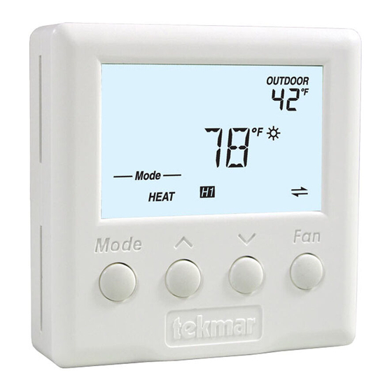
User Interface Display MAIN DISPLAY SECONDARY DISPLAY Switch between Switch between Heat, Cool, Auto Auto, On and % and Off modes Fan operation Adjust the current temperature or displayed setting up or down Symbols Description CLOCK HEAT Operating on a Heat is turned on. -
Page 9: Button Operation
Button Operation - -- - - -- - - -- - - - -- - - -- - - - - - - - - - - - - - - - - -- - - - -- - - - -- - - -- -- - -- -- - -- - - - - - - - - - - - - - - - - - - - - - - - - - - - - - - - - - - - - - - - - - - - - - - - - - - - - - - - - - - - - - - - - Mode The Mode button selects between Auto, Cool, Heat, and Off. - Page 10 © 2010 D 540 - 08/10 10 of 24...
- Page 11 11 of 24 © 2010 D 540 - 08/10...
- Page 12 © 2010 D 540 - 08/10 12 of 24...
- Page 13 13 of 24 © 2010 D 540 - 08/10...
- Page 14 © 2010 D 540 - 08/10 14 of 24...
- Page 15 15 of 24 © 2010 D 540 - 08/10...
-
Page 16: Sequence Of Operation
Sequence of Operation Section A Heating Operation The thermostat operates the heating system to maintain the Set Room Heat temperature. The H1 symbol is shown on the display when the thermostat is heating. The heat can cycle on and off within +/- 1.5°F (1°C) of the Set Room Heat temperature. -
Page 17: Cooling Operation
If the thermostat operates a thermal motor (wax actuator) zone valve, set the Supply Pump setting to Delay. This provides a three minute delay to allow the zone valve to open before the primary or mix pump is turned on and the boiler is allowed to fire. In special applications with multiple zoning manifolds, the Supply Pump setting can be set to Off. -
Page 18: Fan Operation
Section C Fan Operation The thermostat normally operates the fan together with the heating and cooling systems. This is determined by the Fan Mode setting in the Adjust menu. Fan Mode The fan operates with... Not With Heating Nor Cooling (Only with fan button) Cooling Only Heating and Cooling Heating Only... -
Page 19: Schedules
Section D Schedules Lowering the room temperature setting reduces the amount of fuel required to heat the building resulting in energy savings. Likewise, raising the cooling temperature results in energy savings. This thermostat can follow a programmable schedule in order to automatically lower the room temperature setting. -
Page 20: Troubleshooting
© 2010 D 540 - 08/10 20 of 24... - Page 21 21 of 24 © 2010 D 540 - 08/10...
-
Page 22: Frequently Asked Questions
Frequently Asked Questions Symptom Look for... Corrective Action H1 symbol indicates heat is on. Check if zone H1 Symbol valve or zone pump is operating. ® Flashing Increase WWSD setting on tekmarNet WWSD reset control. No Heat Flashing Change User Switch to Normal scene 1. Away Mode Auto or Press Mode button to Auto or Heat mode. -
Page 23: Job Record
Job Record Jobsite Location ________________________________________________ Thermostat Location _____________________________________________ Item Setting Item Setting Min Set Room Cool Set Room Heat Set Room Heat Max Set Room Cool Set Room Heat Away Ventilation Fan Mode Set Room Cool Set Room Cool Set Room Cool Away Backlight Schedule Member Units... -
Page 24: Limited Warranty And Product Return Procedure
(24) months from the production date. The liability of tekmar under the Limited Warranty shall be limited to, at tekmar’s sole discretion: the cost of parts and labor provided by tekmar to repair defects in materials and / or workmanship of the defective product; or to the exchange of the defective product for a warranty replacement product;...
Need help?
Do you have a question about the D540 and is the answer not in the manual?
Questions and answers