Table of Contents
Advertisement
Quick Links
- Wiring Brochure
tekmarNet
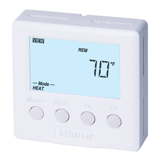
4 Thermostat 542
®
1
2
Information
Application
Brochure
Choose controls
Design your
to match
mechanical
application
applications
Overview
The following brochure describes how to wire the tekmar tekmarNet
heat stage. The 542 has inputs for two auxiliary sensors. The wiring of 542 thermostat is simple and cost effective.
Table of Contents:
Definitions .......................................................................2
Rough-In Wiring .............................................................2
Remove The Wiring Cover ..............................................3
Mounting The Thermostat ...............................................3
Wiring Symbols ...............................................................3
3
Layout
Brochure
Brochure
Rough-in
wiring
instructions
Auxiliary
Sensors
4
Wiring
Brochure
Wiring and
installation of
specific control
4 (tN4) thermostat 542. The 542 has outputs for one
®
tN4
Network
24 V (ac)
Power
1st Stage
Heating
Electrical Drawings ......................................................3-5
Wiring The Thermostat ....................................................6
Troubleshooting The Wiring .............................................7
Testing The Wiring ...........................................................7
Technical Data ................................................................8
1 of 8
5
6
Data
Brochure
Control settings
Record settings &
and sequence of
wiring details for
operation
future reference
DIP
Switches
© 2008
W 542
12/08
Job
Record
W 542 - 12/08
Advertisement
Table of Contents

Related Manuals for Tekmar 542


Summary of Contents for Tekmar 542
- Page 1 The following brochure describes how to wire the tekmar tekmarNet 4 (tN4) thermostat 542. The 542 has outputs for one ® heat stage. The 542 has inputs for two auxiliary sensors. The wiring of 542 thermostat is simple and cost effective. Auxiliary Sensors...
- Page 2 2 Cond. / 18 AWG Sensor 1 1st Stage Heat 4 Cond. / 18 AWG Zone Manager 24 V (ac) Power tN4 Network © 2008 W 542 - 12/08 2 of 8...
- Page 3 Electrical Drawings The electrical drawing examples on the following determine the necessary components for and configuration pages show the 542 in common applications. Choose of the particular system being designed including additional the drawing that most accurately depicts the components...
- Page 4 Sensor 1 = Floor Sensor 2 = Outdoor Outdoor Sensor Slab Sensor 542 tNt Factory installed jumper connects R to Rh (terminals 3 to 4) To isolate W relay, Zone Managers cut jumper © 2008 W 542 - 12/08 4 of 8...
- Page 5 Sensor 071 Factory installed jumper connects R to Rh (terminals 3 to 4) To isolate W relay, Other tN4 Thermostat External Class 2 cut jumper or Zone Manager Transformer 24 V (ac) 5 of 8 © 2008 W 542 - 12/08...
- Page 6 • • Connect sensor 2 to terminals S2 and Com. Outdoor 7 S1 Sensor Do not apply power to terminals 6 - 8, permanent damage to the sensors and / or thermostat will result! 6 Com © 2008 W 542 - 12/08 6 of 8...
- Page 7 3. Install the front cover. Testing the Relays 1. Remove the front cover from the thermostat. 542 LCD Display Segments 2. Disconnect the wires from the relay that is to be tested. 3. Use an electrical test meter and check for continuity across the relay.
- Page 8 None – Optional tekmar type # 071, 070, 072, 073, 076, 077, 078, 079, 082, 084 The installer must ensure that this control and its wiring are isolated and / or shielded from strong sources of electromag- netic noise. Conversely, this Class B digital apparatus complies with Part 15 of the FCC Rules and meets all requirements of the Canadian Interference-Causing Equipment Regulations.
Need help?
Do you have a question about the 542 and is the answer not in the manual?
Questions and answers