
Related Manuals for Extech Instruments PQ3470-2


Summary of Contents for Extech Instruments PQ3470-2
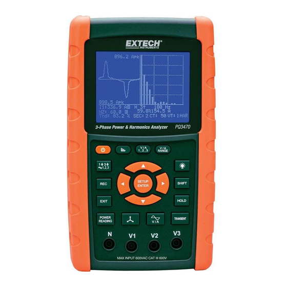
- Page 1 User Guide 3-Phase Power and Harmonics Analyzer / Datalogger MODEL PQ3470 800.561.8187 information@itm.com www. .com...
-
Page 2: Table Of Contents
Table of Contents 1.0 INTRODUCTION 1-1 Features....................3 1-2 Safety ....................... 4 2.0 SPECIFICATIONS 2-1 General Specifications ................. 5 2-2 Electrical Specifications ..................6 3.0 METER DESCRIPTION ............. .8 4.0 METER BASICS AND THE SETUP MODE 4-1 Initialization Screen ...................... 10 4-2 Measurement Screen Example ................ -
Page 3: Introduction
1.0 Introduction Congratulations on your purchase of the Model PQ3470 Power Analyzer. This instrument is fully tested and calibrated prior to delivery; proper use and care of this meter will provide years of reliable service. 1.1 Features Large dot-matrix, numerical, backlit LCD ... -
Page 4: Safety
1.2 Safety CAUTION: Risk of electric shock. Do not attempt to open or disassemble the meter while taking measurements CAUTION: Do not attempt to measure Voltage or Current that exceeds specified limits Do not operate this instrument in wet or dusty environments. ... -
Page 5: Specifications
2.0 Specifications 2.1 General Specifications Circuit Custom single-chip microprocessor LSI circuit LCD Size: 81.4 X 61 mm (3.2 X 2.4”) Display Dot Matrix backlit LCD (320 X 240 pixels) Measurements V (voltage phase to phase) V (voltage phase to ground) A (Current Phase to ground) KW / KVA/ KVAR / PF (Phase) KW / KVA/ KVAR / PF (System) -
Page 6: Electrical Specifications
Real time data logger saves data to SD memory card for download to Datalogger PC (data files open directly to spreadsheet) Sampling rate: From 2 seconds to 7200 seconds Max. file capacity: 30,000 records Data Output Serial or USB connection (cable supplied) Operating Temperature 0 to 50 C (32 to 122... - Page 7 Harmonics Magnitude Range Resolution Accuracy (>5%, 50/60Hz) 1 to 20th ± (2% + 5 digits) 21 to 30th 0.1V ± (4% + 5 digits) 31 to 50th Reference only 1 to 20th ± (2% + 5 digits)* 21 to 30th 0.001A to 1A ±...
-
Page 8: Meter Description
3.0 Meter Description Meter Front, Top, and Right Side 3-1 LCD Display 3-2 Keypad (broken out below) 3-3 Measurement input terminals 3-4 SD CARD slot, RS232 jack, AC adaptor jack, Reset button (broken out below) 3-5 Clamp Power Output jacks (broken out below) PQ3470-en-GB_V1.9 10/15 800.561.8187 information@itm.com... - Page 9 Keypad Description 3-6 Display Backlight ON-OFF 3-18 3-7 Power ON-OFF 3-23 3-24 3-10 3-8 Exit (programming) 3-9 REC datalogger memory 3-10 Volt/Amp range 3-12 3-22 3-11 Shift (programming) 3-21 3-12 Setup / Enter 3-11 3-13 HOLD (freeze display) 3-20 3-14 Transient display 3-13 3-15 V/A Waveform display 3-16 Phasor display...
-
Page 10: Meter Basics And The Setup Mode
4.0 Meter Basics and Setup Mode 4-1 Initialization Screen 1. When the meter is switched ON the initialization screen appears (see Fig. 4-1 below). Figure 4-1: Start-up Initialization Screen 2. The meter will also check for an inserted SD memory card. ‘SD check’ will appear on the lower right side of the display. -
Page 11: Keypad Summary
4.3 Keypad Summary POWER : Press and hold to power ON/OFF 1Φ 3Φ (phase/wire) : Select (1P/2W, 1P/3W, 3P/3W, 3P/4W) measurement functions REC : Data record key for the SD Memory Card HOLD: Freeze the displayed reading ... -
Page 12: Setup Mode Basics
4.4 Setup Mode 4.4.1 Setup Mode Basics 1. Press the SETUP button to access the Setup Mode. The screen shown below will appear on the meter’s LCD. 2. Use the up and down arrow keys to scroll through the parameters. 3. - Page 13 Setup Mode Screen with SHIFT 2 icon 4.4.2 The Setup Mode Parameter Menu Folder Name: Select a file name on the SD CARD; the range is WTA01 to WTA10 File Name: Set a file name on the SD CARD (50 filenames are permitted) ...
-
Page 14: Setup Mode In Detail
4.5 Setup Mode in Detail Press SETUP to enter the Setup Mode, selected items will appear highlighted (reverse video). As described in the Setup Mode Basics section above, use the up and down arrow keys to move through the available parameters and use the Shift key to open a parameter for editing. Once a parameter is opened for editing, the up and down arrow keys are used again to change a parameter’s setting. - Page 15 4.5.2 File name: Set a file name in the SD Memory Card In the Setup Mode, scroll down to the FILE NAME parameter using the up and down arrow keys The screen will show the "NO FILE" indicator in the REC Date option area when the selected file is new.
- Page 16 File Name (Screen 3) File Name (Screen 4) 4.5.3 Set the Sampling Time (datalogging rate) for recording onto the SD Memory Card In the Setup Mode, use the up and down arrow keys to scroll to the SAMPLING TIME field. Press the SHIFT key and the symbol "SHIFT1"...
- Page 17 4.5.4 Delete a file on the SD Memory Card In the Setup Mode, scroll to the DELETE FILE field using the up and down arrow keys. Press and hold the SETUP/ENTER key for at least 2 seconds and the indicators “Y” and “N”...
- Page 18 4.5.9 Transient Reference (Trans. Ref.) The Transient Reference parameter sets the nominal voltage used for a transient detect reference. In the Setup Mode, use the up and down arrow keys to scroll to the TRANS REF field. Press SHIFT, the display "SHIFT1" will switch ON Use the ▲...
- Page 19 4.5.14 Set Voltage Range In the Setup Mode, use the up and down arrow keys to scroll to the “V RANGE” field. Press SHIFT, the display "SHIFT1" will switch ON Use the ▲ or ▼ keys to select the voltage (Note that unless the CLAMP TYPE is set to OTHER, this value is fixed) Press SHIFT again to return to Setup Mode editing or press EXIT to leave the Setup mode.
- Page 20 4.5.16 Set Time and Date In the Setup Mode, use the up and down arrow keys to scroll to the YEAR, MONTH, DATE, HOUR, MINUTE, and SECOND fields. Press SHIFT key when the desired field is selected, the display "SHIFT1" will switch ON Use the ▲...
-
Page 21: Power Measurement Procedures
5.0 Power Measurement Procedures 1Φ2W (Single Phase - Two Wire) Measurement Power the instrument ON by pressing the ‘Power’ key (item 3-7; Section 3 diagrams), and then use the ‘1Φ 3Φ’ key (item 3-22) to select the 1Φ 2W system, the selected name of the system will be shown on the bottom left side of the display (refer to Figure 5-1 below) Connect the line voltage L1, Vn (Neutral) to V1 and N terminals of the instrument. -
Page 22: 3W (Single Phase Three Wire) Measurement
1Φ3W (single phase - three wire) Measurement Power the instrument ON by pressing ‘Power’ key (item 3-7; Section 3 diagrams), and then press the ‘1Φ 3Φ’ key (item 3-22) to select 1Φ 3W, the selected name of the configuration will appear on bottom left hand side of the display. Connect the line voltage L1, L2 and Vn (Neutral) to V1, V2 and N terminals of the instrument Connect the two (2) clamps (A1 and A2) to the conductors (A1) and (A2) -
Page 23: 3W (Three Phase Three Wire) Measurement
3Φ 3W (three phase - three wire) Measurement Power the instrument ON by pressing the ‘Power’ key (item 3-7; Section 3 diagrams), and then press ‘1Φ 3Φ’ (item 3-22) to select 3Φ 3W, the selected configuration name will appear on bottom left hand side of the display. Connect the line voltage L1, L2 and L3 to V1, V2 and V3 terminals of the instrument. -
Page 24: 4W (Three Phase Four Wire) Measurement
3Φ 4W (three phase - four wire) Measurement Power the instrument ON by pressing the ‘Power’ key (item 3-7; Section 3 diagrams), and then press ‘1Φ 3Φ’ (item 3-22) to select the 3Φ 4W system, the selected name of the system will appear on the bottom left hand side of the display. -
Page 25: Ct And Pt Measurement
5.5 Current (CT) / Potential (PT) Transformer Measurement Power the instrument ON by pressing the ‘Power’ key (item 3-7; Section 3 diagrams), and then press the ‘1Φ 3Φ’ key (item 3-22) to select the 3Φ 4W system, the selected name of the system will appear on the bottom left hand side of the display. -
Page 26: Zero Adjust For Watt Hour Measurement
5.6 – Zero Adjustment for the ‘Watt Hour’ Function Press and hold the "Exit” key for at least 6 seconds, the measurement values for "WH", "SH", "QH" will reset to a Zero value. 5.7 – Harmonic Function Measurements (View only) Press the ‘Harmonic’... - Page 27 Harmonics - Screen 3– Voltage phase 1 – High range (VH) Harmonics - Screen 4– Amps phase 1 – High range (AH) Harmonics Display Definitions: Crest Factor Amps – Ratio of Peak value to RMS value Crest Factor Voltage – Ratio of Peak value to RMS value Pk-Pk Peak to Peak valuie of voltage or amperage AH/AL...
-
Page 28: Graphic Phasor Measurement
5.8 – Graphic Phasor Diagram 1. Press the Phasor key to display the Phasor as shown in Screen 1 for Figure 5-8a below. 2. Description of Phasor diagram: V1, V2, V3: Phase voltages in phasor format with respect to V1 ... -
Page 29: Voltage Current Waveform
5.9 – Voltage Current Waveform 1. Press Waveform to enter the Voltage Waveform screen as shown in Screen 1 below, and then Press the "1Φ /3Φ” key to switch the Voltage waveform from V1 to V2 to V3, etc. 2. Press the Waveform key again to enter the Current Waveform screen as shown in Screen 2 below, and then press the "1Φ... -
Page 30: Transient Capture (Dips, Swells, Outage)
5.10 – Transient Capture (Dips, Swells, and Outages) 1. To use the Transient Capture function, first set the Transient Reference Voltage level and the SDVP (Swell/Dip voltage percentage) value per sections 4-5-9 and 4-5-10 respectively. 2. Press the TRANSIENT key to enter the Transient Capture screen. 3. -
Page 31: Data Logger
5.11 – Datalogger Function Press the REC key once to begin. If the meter displays the "Change Card" message at the bottom right, the SD CARD memory is either full or it is damaged. If the meter displays “NO DISK” an SD card must be inserted before datalogging can begin. -
Page 32: Data Hold
5.12 – Data Hold Function During a measurement, press the HOLD KEY once, the displayed readings will freeze and the display will show the “HOLD” icon on the bottom right side of the screen Press the HOLD key again to release the display and return to the normal operating mode. The HOLD display icon will switch off The HOLD display 5.13 –... -
Page 33: Measurement Definitions
5.15 Measurement Definitions V12, V23, V31 : Line Voltage V1, V2, V3 : Phase Voltage A1, A2, A3 : Line Current P1, P2, P3 : True Power of each phase (W) S1, S2, S3 : Apparent Power of each phase. (VA) ... -
Page 34: Maintenance
6.0 Maintenance CAUTION: Remove test leads before opening the battery cover; Electrical Shock Hazard. 6.1 Cleaning CAUTION: When cleaning, use only a dry cloth. Do not use liquids of any kind to clean the meter. 6.2 Battery Replacement When the display shows the LOWBAT indicator, replace the batteries as soon as possible Open the rear Battery Cover and remove the batteries Replace the eight (8) batteries (1.5Vdc ‘AA’... -
Page 35: Sd Card
7.0 SD Card 7.1 Download SD Card Data to PC After a Datalogging session, remove the SD card from the SD card socket. Plug the SD card into a PC SD card reader slot or into an SD card reader adaptor. Power the computer and run spreadsheet software. - Page 36 User's Guide 200A Current Probe Set Model PQ34-2 800.561.8187 information@itm.com www. .com...
- Page 37 Introduction Congratulations on your purchase of this Extech Current Probe Set. A set of three 200A current probes designed to be used with the Extech PQ3450 or PQ3470 Power Analyzers. These probes are shipped fully tested and calibrated and, with proper use, will provide years of reliable service. Safety This symbol, adjacent to another symbol or terminal, indicates the user must refer to the manual for further information.
- Page 38 Probe Description Current Sensing Jaws Jaw Trigger 1200A-200A-20A range switch Signal output plug ( +, red ) Signal output plug ( -, black ) DCV power plug Operation Connect the “A1” signal output cables to the matching input sockets on the top of the analyzer. Connect the “A1”...
- Page 39 Specifications Measurement ranges 20A and 200A, switch selectable Output sensitivity 10mV/A (20A range) 1mV/A (200A range) Output coupling AC coupled. Accuracy (50/60Hz) ± 1% F.S. @ 23 ± 5°C (50/60Hz) Frequency range 45 to 400 Hz. Phase error (50/60Hz) < ± 1° (50/60Hz) Minimum load 100 K ohm for specified accuracy Enclosure material...
Need help?
Do you have a question about the PQ3470-2 and is the answer not in the manual?
Questions and answers