Table of Contents
Advertisement
Advertisement
Table of Contents

Related Manuals for Extech Instruments 42280A


Summary of Contents for Extech Instruments 42280A
- Page 1 User Manual Temperature & Humidity Datalogger Model 42280A...
-
Page 2: Table Of Contents
Table of contents Introduction................1 Overview ..............1 Product Features ............1 Supplied Material............1 Optional Accessories ..........2 Quick Start (en)..............3 Product Description ............4 Front Panel Description..........4 Display and LED Indicators ........... 5 3.2.1 Display Description .......... 5 3.2.2 LED Indicators .......... - Page 3 Table of contents Alarm Thresholds ............. 20 Alarm Delay Timer ............ 20 Alarm Alerts ............20 Alarm Statistics ............21 Relative Humidity Calibration ..........22 Calibration Overview ..........22 Calibration Process ........... 22 Calibration Notes............22 Specifications..............23 Two-year Warranty............. 24 10.1 Calibration and Repair Services........
-
Page 5: Introduction
The 42280A can monitor environmental conditions in a variety of residential and commercial storage and in-transit locations. The 42280A is easy to use, offering a large display monitor, a five (5) button keypad, two (2) LED indicators, and an alert beeper. The 42280A is supplied with PC software that makes configuring the logger, and setting global param- eters, very convenient. -
Page 6: Optional Accessories
Introduction 1.4 Optional Accessories The following equipment can be ordered separately. Contact your Extech sales representative for more information. • 9 V power adapter. The adapter is recommended for long datalogging sessions. • Relative humidity calibration salt solution bottles for 33% and 75% references. -
Page 7: Quick Start (En)
Long press the START/STOP button to stop logging. The green LED and the REC display icon will stop flashing. Connect the 42280A to a PC to generate the PDF and text file reports. See Section 6 for complete details. Short press the power button to switch off the 42280A. -
Page 8: Product Description
Product Description 3.1 Front Panel Description Figure 3.1 42280A front panel. 1. Temperature (thermistor) and RH (capacitive) sensor. 2. Alarm LED. Flashes every 10 seconds in an alarm condition. 3. Audio beeper. 4. Power ON/OFF and Datalogger Start/Stop button (see Section 3.3 for complete button operation instructions). -
Page 9: Display And Led Indicators
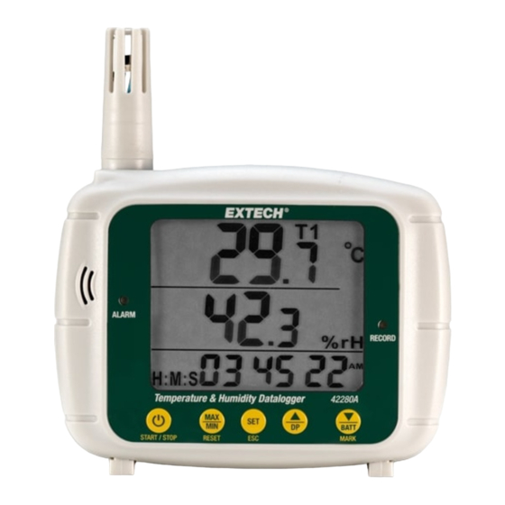
Product Description 3.2 Display and LED Indicators 3.2.1 Display Description Figure 3.2 Display description. 1. Appears when Dew Point (DP) temperature is displayed on middle display row. 2. Temperature (T1) reading (updates every 10 seconds or at the sampling rate while datalogging). 3. -
Page 10: Led Indicators
Product Description 3.2.2 LED Indicators Two color LED indicators are located on the front panel. The red LED (Alarm) is located on the left side of the meter display. It flashes every 10 seconds when a temperature or RH measurement exceeds the programmed alarm lim- its. -
Page 11: Back Of Meter
Product Description 3.4 Back of Meter The wall mounting hole (1) and the battery compartment (2) are located on the back of the meter. Figure 3.4 Back of meter showing wall mount hole (1) and battery compartment (2). 3.5 Bottom of Meter The tripod mount (1) and the two detachable footer stands (2) are located on the bottom of the unit. -
Page 12: Monitoring Mode
Monitoring Mode 4.1 Monitoring Mode Overview The 42280A is in the monitoring mode when it is powered but not datalogging. In the monitoring mode you can view measurement readings in real time and perform other functions as detailed below. See Section 3.2 for a description of the display characters. -
Page 13: Max / Min Memories
MAX / MIN Memories The 42280A records and displays the highest and lowest temperature and RH readings. Short press the MAX/MIN button to step through the highest readings recorded (MX is shown), lowest readings recorded (MN is shown), and back to real time readings (MX and MN indicators switch off). -
Page 14: Datalogger Mode
6.2.1 Configuring the Datalogger using a PC Note: If the 42280A shows ‘dlF (datalogging file)’ on its display, when con- nected to the PC, a datalogger file has been previously saved and is ready for download. - Page 15 Once established, the green LED will switch off, the text ‘PC’ will appear on the display, and the PC will create a new external storage drive for the 42280A in Windows File Explorer. 3. The storage drive will include a software application entitled ‘PDF Logger Configuration Tool’.
- Page 16 Click to abort a configuration session. To complete and confirm the configuration, click ‘SAVE’, close the setup win- dow, eject the 42280A from the PC (right-click the drive icon on the PC and select ‘Eject’), and then disconnect the logger from the USB port.
-
Page 17: Configuring The Datalogger Using The Front-Panel Keypad
(P1 to P8) must be displayed in order to exit. Note: If the 42280A shows ‘dlF’ (datalogging file)’ on its display, when you press the SET button, this indicates that a log file is in the meter’s internal memory and must be downloaded before you can configure the datalogger with the keypad (see Section 6.5). -
Page 18: Starting The Datalogger
Datalogger Mode Units Setting Select ℃ or ℉ temperature units (Unt), shown on the (P7) middle row. Real Time Set the logger’s real time clock (rtc) to the local time. Set Clock (P8) the Year (Y), Month (M), Day (D), Hours (H), Minutes (M), Seconds (S) on the bottom row. -
Page 19: Putting The Display To Sleep While Logging
Datalogger Mode point an exact time when the logger was moved to a new test location or when a sudden environmental change was noticed, for example. 6.3.3 Putting the Display to Sleep while Logging While the logger is running, you can short press the START/STOP button, just as you would to switch the meter off, to switch off only the display. - Page 20 Datalogger Mode Figure 6.2 PC download window example. 1. Click the ‘Convert to PDF’ or the ‘Convert to Excel’ tab. 2. Select the desired report language. 3. Click the ‘SAVE’ button. 4. In the ‘Save As’ window, name the file, choose a storage location for the log report, and click ‘Save’.
-
Page 21: Pdf Log Report
Datalogger Mode 6.6 PDF Log Report After you complete the steps in Section 6.5, for downloading data and open- ing a PDF file, the PDF report shown below will be opened and saved to your PC. The units of measure and language used in the report are selected in the configuration process (Section 6.2). - Page 22 Datalogger Mode 2. Logger serial number and OK indicator (informs that no alarms were triggered). 3. Factory information and date the log file was created. 4. Logger configuration other logging details. 5. Temperature Alarm report. For Alarm information see Section 7. 6.
-
Page 23: Text File Log Report
Datalogger Mode 6.7 Text File Log Report After you complete the steps in Section 6.5 for downloading data to a text file, the report shown below will be opened and saved to your PC. The information in the text file is essentially the same as the information shown in the PDF re- port (refer to Section 6.6 and Section 7 for report details and alarm statistical information listed in the text file report below). -
Page 24: Alarms
Alarms 7.1 Alarm Overview The 42280A has a temperature and a RH alarm function. Alarms function in both Monitoring mode (when not logging) and in the Datalogging mode. The front panel Alarm LED flashes when an alarm is triggered. 7.2 Alarm Types The alarm type is selected in the configuration process. -
Page 25: Alarm Statistics
7.6 Alarm Statistics When logging data, the 42280A records the following readings and calcula- tions. These are provided in the logging reports generated by the 42280A as shown in Sections 6.6 and 6.7. • Maximum readings: Highest readings recorded over the course of the da- talogging session. -
Page 26: Relative Humidity Calibration
Relative Humidity Calibration 8.1 Calibration Overview The 42280A can be calibrated by the user, or it can be returned to Extech for service. Field calibration requires the use of optional 33% and 75% calibration salt bottles. Contact your local distributor, or Extech directly, for information re- garding the purchase of calibration bottles. -
Page 27: Specifications
Specifications Range* Resolution Accuracy at 77℉ ℉ (25℃ ℃ ) 0.1° Temperature -22 to 158℉ (-30 to 70℃) ± 0.9℉ (0.5℃) measurements RH measurements 0.1 to 99.9% 0.1% ± 3% from 10 to 90% (otherwise ±5%) 0.1° Dew Point 32 to 122℉ (0 to 50℃) calculation Temperature sensor NTC thermistor. -
Page 28: Two-Year Warranty
Two-year Warranty FLIR Systems, Inc. warrants this Extech brand instrument to be free of defects in parts and workmanship for two years from date of shipment (a six- month limited warranty applies to sensors and cables). To view the full war- ranty text please visit: http://www.extech.com/support/warranties. - Page 30 User Manual last page Website http://www.flir.com Customer support http://support.flir.com Copyright © 2022, FLIR Systems, Inc. All rights reserved worldwide. Disclaimer Specifications subject to change without further notice. Models and accessories subject to regional market considerations. License procedures may apply. Products described herein may be subject to US Export Regulations.
Need help?
Do you have a question about the 42280A and is the answer not in the manual?
Questions and answers