Table of Contents
Advertisement
Quick Links
Advertisement
Table of Contents

Related Manuals for Extech Instruments PQ3470


Summary of Contents for Extech Instruments PQ3470
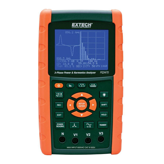
- Page 1 User Guide 3-Phase Power and Harmonics Analyzer / Datalogger MODEL PQ3470...
-
Page 2: Table Of Contents
5-14 LOWBAT (Low Battery) screen ..............32 5-15 Measurement Definitions .................. .33 5-16 Reset Button ......................33 6.0 MAINTENANCE 6-1 Cleaning ......................... 34 6-2 Battery Replacement .................... 34 7.0 SD Card 7-1 Download Data from SD Card ............35 PQ3470-en-GB_V1.9 10/15... -
Page 3: Introduction
1.0 Introduction Congratulations on your purchase of the Model PQ3470 Power Analyzer. This instrument is fully tested and calibrated prior to delivery; proper use and care of this meter will provide years of reliable service. 1.1 Features Large dot-matrix, numerical, backlit LCD ... -
Page 4: Safety
Safety Symbols: CAUTION DOUBLE INSULATION RISK OF ELECTRIC SHOCK Environmental Conditions Installation Category III 600V Pollution Degree 2 Altitude limit: 2000m Indoor use only Relative Humidity maximum: 80% PQ3470-en-GB_V1.9 10/15... -
Page 5: Specifications
Data on SD card will read ‘9999’ or ‘999’ for over-range data Under-range "UR" is displayed Data Hold Freezes displayed reading Data Recording SD memory card SD Card capacity 2G SD max. / 16G SDHC max. Sampling Time Approx. 1 second (LCD) / 2000 samples per period PQ3470-en-GB_V1.9 10/15... -
Page 6: Electrical Specifications
0.001k to 0.001M ± (1% range+8 digits)* 0.0 to 3.6MVAR Watt-Hour 0.0 to 3.6MWH 0.0 to 3.6MVAH 0.001k to 0.001M ± (1% range+8 digits)* 0.0 to 3.6MVARH *Meter accuracy only. For system accuracy add the accuracy of the clamp used. PQ3470-en-GB_V1.9 10/15... - Page 7 0.1° ± 2° *Meter accuracy only. System accuracy includes the accuracy of the clamp used. PFH: Long Term Power Factor PF ∑: For 3ɸ4W, 3 ɸ3W, 1 ɸ3W: PF ∑ = p∑/ S∑ For 1ɸ2W: PF1 = P1/S1 PQ3470-en-GB_V1.9 10/15...
-
Page 8: Meter Description
Meter Front, Top, and Right Side 3-1 LCD Display 3-2 Keypad (broken out below) 3-3 Measurement input terminals 3-4 SD CARD slot, RS232 jack, AC adaptor jack, Reset button (broken out below) 3-5 Clamp Power Output jacks (broken out below) PQ3470-en-GB_V1.9 10/15... - Page 9 3-29 Screw fastener for protective cap Meter Top 3-30 Clamp positive input jacks 3-31 Clamp negative input jacks 3-32 Clamp power lead connections Note: The Battery compartment and Tilt Stand are located on the rear of the instrument PQ3470-en-GB_V1.9 10/15...
-
Page 10: Meter Basics And The Setup Mode
After the initialization screen, the meter then displays one of the measurement screen configurations. The meter reverts to the screen that was displayed at the last power down and may not be the screen shown below. Other screen configurations are shown later in this User Guide. Measurement Screen Example PQ3470-en-GB_V1.9 10/15... -
Page 11: Keypad Summary
: View waveform representations of voltage and current Phase diagram : View measurements in vector display format Power Reading : Display power measurements Harmonics display : Display Harmonics Harmonics Analysis : View the Harmonics analysis PQ3470-en-GB_V1.9 10/15... -
Page 12: Setup Mode Basics
SETUP key to open the multi-page RS-232 output selection. Refer to the RS-232 section of this guide for more detailed information. 8. To exit the Setup Mode press the EXIT key. 9. Detailed instructions for each parameter are provided in the next section. Setup Mode Screen with SHIFT 1 icon PQ3470-en-GB_V1.9 10/15... - Page 13 RS232 section of the user guide for detailed information Year: Set the current year Month: Set the current month Date: Set the current date Hour: Set the current hour Minute: Set the current minute Second: Set the current second PQ3470-en-GB_V1.9 10/15...
-
Page 14: Setup Mode In Detail
4. Use the arrow keys ▲ ▼ to select a folder number; the available numbers are "01 to 10" (Note: Press and hold ▲ or ▼ continuously for at least two seconds to scroll quickly). 5. Press SHIFT when done Folder Name (Screen 1) Folder Name (Screen 2) PQ3470-en-GB_V1.9 10/15... - Page 15 3P301001: 3P3 is three phases by three wires, 01 the folder number, and 001 the file number. 3P401001: 3P4 is three phases by four wires, 01 the folder number, and 001 the file number. Press the SHIFT key again to continue with the Setup Mode editing. PQ3470-en-GB_V1.9 10/15...
- Page 16 Press the SHIFT key and the symbol "SHIFT1" will switch ON. Use the arrow keys to adjust the sampling time; the range is 2 to 7200 seconds. Press the SHIFT key again to return to Setup Mode editing. PQ3470-en-GB_V1.9 10/15...
- Page 17 In the Setup Mode, use the up and down arrow keys to scroll to the BEEP field. Press SHIFT, the display "SHIFT1" will switch ON Use the ▲ or ▼ keys to select ON or OFF Press SHIFT again to return to Setup Mode editing or press EXIT to leave the Setup mode. PQ3470-en-GB_V1.9 10/15...
- Page 18 In the Setup Mode, use the up and down arrow keys to scroll to the “A RANGE” field. Press SHIFT, the display "SHIFT1" will switch ON. Use the ▲ or ▼ keys to select the current range. Press SHIFT again to return to Setup Mode editing or press EXIT to leave the Setup mode. PQ3470-en-GB_V1.9 10/15...
- Page 19 To scroll from page to page, press the SHIFT button momentarily (there are four pages) Press the EXIT button to exit the RS232 output mode. If more than nine items are selected the display will show the indicator "full". RS232 – Output Selection Pages PQ3470-en-GB_V1.9 10/15...
- Page 20 Press SHIFT again to return to Setup Mode editing or press EXIT to leave the Setup mode. 4.5.17 Exit the Setup Mode When all of the programming has been completed, press the EXIT key to return to the measurement mode of operation. PQ3470-en-GB_V1.9 10/15...
-
Page 21: Power Measurement Procedures
Connect the Clamp (A1) to the conductor (A1) Connect Clamp 1 (A1) to the A1 terminal of the instrument The related measurement factors will appear on the display Measurement definitions can be found in Section 5-15 Figure 5-1 PQ3470-en-GB_V1.9 10/15... -
Page 22: 3W (Single Phase Three Wire) Measurement
Connect the two (2) clamps (A1 and A2) to the conductors (A1) and (A2) Connect Clamp 1 and Clamp 2 (A1 and A2) to the A1 and A2 terminals of the instrument The related measurement factors will appear on the display Measurement definitions can be found in Section 5-15 Figure 5-2 PQ3470-en-GB_V1.9 10/15... -
Page 23: 3W (Three Phase Three Wire) Measurement
Connect the three (3) clamps (A1, A2, A3) to conductors A1, A2 , A3 Connect the three (3) Clamps to the meter using the A1, A2, and A3 terminals The related measurement factors will appear on the display Measurement definitions can be found in Section 5-15 Figure 5-3 PQ3470-en-GB_V1.9 10/15... -
Page 24: 4W (Three Phase Four Wire) Measurement
Connect the three (3) Clamps (A1, A2, and A3) to the conductors A1, A2, and A3. Connect the Clamps (A1, A2, and A3) to the meter’s A1, A2, and A3 terminals. The related measurement factors will appear on the display. Measurement definitions can be found in Section 5-15. Figure 5-4 PQ3470-en-GB_V1.9 10/15... -
Page 25: Ct And Pt Measurement
Connect the three (3) Clamps (A1, A2, A3) to the conductors A1, A2, A3 Connect the Clamps (A1, A2, A3) to the meter’s A1, A2, A3 terminals The related measurement factors will appear on the display Measurement definitions can be found in Section 5-15 Figure 5-5 PQ3470-en-GB_V1.9 10/15... -
Page 26: Zero Adjust For Watt Hour Measurement
NOTE: If the waveform is clipped at the peak or too small in the LCD, press the RANGE button to select HIGH or LOW range for a better display. The range indicator is the symbol after the unit of RMS value, L or H. PQ3470-en-GB_V1.9 10/15... - Page 27 – percentage is based on ratio to fundamental signal 3.0° Phase angle of the harmonic frequency Voltage for Phase 1 is displayed Amperage for phase 1 is displayed FREQ Line frequency being measured 1200/20A Clamp model and range setting 3Φ4W 3 phase, 4-wire PQ3470-en-GB_V1.9 10/15...
-
Page 28: Graphic Phasor Measurement
% (d2) of voltage or current. dA%: Historical maximum % for MAX (A123) – MIN (A123) / MIN A123) * 100% AUR: Current ratio (unbalanced) Figure 5-8a: Phasor - Screen 1 Figure 5-8b: Phasor - Screen 2 PQ3470-en-GB_V1.9 10/15... -
Page 29: Voltage Current Waveform
Screen 3 below, and then press the "1Φ /3Φ” key to switch the Voltage/Current waveform from V1/A1 to V2/A2 to V3/A3, etc. Figure 5-9c: Waveforms - Screen 1 Figure 5-9b: Waveforms - Screen 2 Figure 5-9c: Waveforms - Screen 3 PQ3470-en-GB_V1.9 10/15... -
Page 30: Transient Capture (Dips, Swells, Outage)
Figure 5-10a: Transient Capture - Screen 1 NOTE: Each time the 1Φ 3Φ button is pressed, the meter steps through the transient mode wire configuration list (1P2W, 1P3W, 3P3W, and 3P4W) Figure 5-10b: Transient Capture - Screen 2 PQ3470-en-GB_V1.9 10/15... -
Page 31: Data Logger
Press the REC key again to stop datalogging. The incrementing counter and the REC display icon will switch off. Instructions are provided later in this User Guide regarding data exporting to a spreadsheet using a PC. The Datalogger Incrementing Counter display PQ3470-en-GB_V1.9 10/15... -
Page 32: Data Hold
5.14 – Low Battery Indication (LOW BAT) When the LOW BAT indicator appears, replace the batteries as described in the Battery Replacement section of this manual. Use of weak batteries will compromise measurement accuracy and meter performance. Low Battery indication PQ3470-en-GB_V1.9 10/15... -
Page 33: Measurement Definitions
SDVP : Swell and Dip Voltage Percentage (used with Transient Reference Voltage) 5.16 – Reset Button The Reset Button located on the right side of the meter allows the user to reboot the meter if the display or keypad is locked. PQ3470-en-GB_V1.9 10/15... -
Page 34: Maintenance
You can hand over your used batteries / accumulators at collection points in your community or wherever batteries / accumulators are sold! Disposal: Follow the valid legal stipulations in respect of the disposal of the device at the end of its lifecycle PQ3470-en-GB_V1.9 10/15... -
Page 35: Sd Card
The data files can be opened directly into a spreadsheet program. Example Data File Example Graphic Screen Copyright © 2014-2015 FLIR Systems, Inc. All rights reserved including the right of reproduction in whole or in part in any form. ISO-9001 Certified www.extech.com PQ3470-en-GB_V1.9 10/15...
Need help?
Do you have a question about the PQ3470 and is the answer not in the manual?
Questions and answers