Advertisement
Quick Links
INSTALLATION AND MAINTENANCE INSTRUCTIONS
B401R Plug-in Detector Base
For use with the following smoke detectors: 1451E and 2451E
Specifications
Diameter:
Height:
Weight:
Operating Temperature:
Operating Humidity:
Electrical Ratings — includes base and detector
Voltage:
Maximum Ripple Voltage:
Start-up Capacitance:
Standby Ratings:
Alarm Ratings:
Reset Voltage:
Before Installing
Please thoroughly read the System Sensor Manual I56-407,
Guide For Proper Use of System Smoke Detectors, which pro-
vides detailed information on detector spacing, placement,
zoning, wiring, and special applications. Copies of this
manual are available at no charge from System Sensor.
NOTICE: This manual should be left with the owner/user
of this equipment.
IMPORTANT: The detector used with this base must be
tested and maintained regularly following NFPA 72 require-
ments. The detector used with this base should be cleaned
at least once a year.
10.2 cm (4.0 inches)
2.0 cm (0.8 inches)
152 g (0.34 lb.)
–10° to +60° C (14° to 140° F)
10% to 93% Relative Humidity
24 VDC
4 Volts peak to peak
0.02 µ F Maximum
15 VDC Minimum
32 VDC Maximum
120 µ A Maximum
10 mA Minimum at 10.5 VDC
62mA Maximum at 32 VDC
(If used, the RA400Z Remote Annunciator operates within the specified
detector alarm currents.)
2.5 VDC Minimum
General Description
The B401R plug-in detector base is used with System Sen-
sor model 2451E photoelectronic detector head and model
1451E ionization detector head. The capability of plugging
these detectors into a variety of special bases makes them
more versatile than equivalent direct-wired models. Refer
to the System Sensor catalog for other plug-in detector
bases.
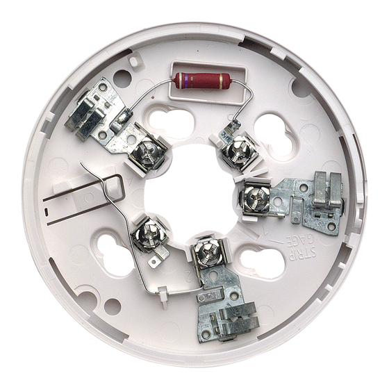
The B401R base is intended for use in 2-wire systems, with
screw terminals provided for power, ground, and remote
annunciator connections. The B401R base also contains a
resistor to provide current limiting in the alarm state.
1
firealarmresources.com
A Division of Pittway
System Sensor Europe
Via Caboto 19, 34143, Trieste, Italy
I56-351-03
Advertisement

Subscribe to Our Youtube Channel
Related Manuals for System Sensor B401R


Summary of Contents for System Sensor B401R
- Page 1 NOTICE: This manual should be left with the owner/user bases. of this equipment. The B401R base is intended for use in 2-wire systems, with IMPORTANT: The detector used with this base must be screw terminals provided for power, ground, and remote tested and maintained regularly following NFPA 72 require- annunciator connections.
- Page 2 Base Terminals Figure 1. Terminal layout: FUNCTION REMOTE ANNUNCIATOR (+) NEGATIVE (–) V IN, REMOTE ANNUNCIATOR (–) NEGATIVE (–) V OUT NOT USED POSITIVE (+) V IN AND V OUT NOTE: If remote annunciator is not used, polarity to these terminals may be reversed.
- Page 3 Figure 3. Typical wiring diagram for 2-wire detector system: – NOTE: IF REMOTE ANNUNCIATOR IS NOT USED, POLARITY TO THESE TERMINALS MAY BE REVERSED. – – REMOTE REMOTE ANNUNCIATOR ANNUNCIATOR A78-1175-05 CLASS A OPTIONAL WIRING CAUTION Do not loop wire under terminals. Break wire run to provide supervision of connections. This temporary connection permits the wiring of the loop To activate this feature, break off the tab on the detector to be checked for continuity before installation of the...
- Page 4 Three-Year Limited Warranty Repair Department, RA #__________, 3825 Ohio Avenue, St. Charles, IL System Sensor warrants its enclosed smoke detector base to be free from defects in materials and workmanship under normal use and service for a 60174. Please include a note describing the malfunction and suspected period of three years from date of manufacture.
Need help?
Do you have a question about the B401R and is the answer not in the manual?
Questions and answers