Table of Contents
Advertisement
Quick Links
INSTALLATION AND MAINTENANCE INSTRUCTIONS
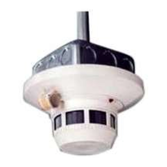
B404BT Plug-in Detector Base
Specifications
Base Diameter:
Base Height:
Weight:
Operating Temperature Range:
Operating Humidity Range:
Electrical Ratings – includes base and detector
System Voltage:
Relay Contact Ratings
Resistive or Inductive (60% power factor) load
Form A:
Form C:
Start-up Time:
(After 60 second reset)
Before Installing
Please thoroughly read System Sensor's manual I56-407,
Guide for Proper Use of System Smoke Detectors. This
manual provides detailed information on detector spacing,
placement, zoning, wiring, and special applications, and is
available at no charge from System Sensor.
NOTICE: This manual should be left with the owner/user
of this equipment.
IMPORTANT: The detector used with this base must be
tested and maintained regularly following NFPA 72 re-
quirements. The detector used with this base should be
cleaned at least once a year.
General Description
The B404BT detector base is designed for use with Sys-
tem Sensor model 2451 and 2451TH photoelectronic and
1451 ionization detector heads. The capability of plug-
ging these detectors into a variety of special bases
makes them more versatile than equivalent direct-wired
models. Refer to the System Sensor catalog for other
available plug-in bases. The B404BT base is intended for
use in 4-wire systems with terminals provided for re-
mote annunicator and relay connections.
D450-10-00
6.2 inches (15.7 cm)
1.1 inches (2.9cm)
0.6 lb. (260 g)
4-inch square box without plaster ring. Minimum depth–1.5 inches
4-inch octagon box. Minimum depth–1.5 inches
0° to 49° C (32° to 120° F)
10% to 93% Relative Humidity
24 VAC/DC, 60 Hz
2.0A @ 30VAC/DC
2.0A @ 30VAC/DC
0.6A @ 110VDC
1.0A @ 125VAC
(If used, the RA400 Remote Annunciator and RTC operates within the specified detec-
tor system voltage.)
36.0 Seconds maximum
1
3825 Ohio Avenue, St. Charles, Illinois 60174
Power
Wire leads are provided for 24 VAC/DC power operation.
A Division of Pittway
1-800-SENSOR2, FAX: 630-377-6495
I56-530-03
Advertisement
Table of Contents

Subscribe to Our Youtube Channel
Related Manuals for System Sensor B404BT


Summary of Contents for System Sensor B404BT
- Page 1 The detector used with this base should be cleaned at least once a year. General Description The B404BT detector base is designed for use with Sys- tem Sensor model 2451 and 2451TH photoelectronic and 1451 ionization detector heads. The capability of plug-...
- Page 2 Base Terminals Figure 1. Base Terminals Function Remote Annunciator (+) Test Coil (+) Not used Remote Annunciator (-) RTC (-) N.O. Supervisory Relay Form A Contacts N.O. Alarm Relay N.O. Form A Initiation Contacts N.O. Alarm Relay N.C. Form C Auxiliary Contacts Mounting The detector base mounts directly to 4-inch octagon boxes...
- Page 3 Figure 3. Typical Wiring Diagram for 24VAC rms/DC Detector Systems APA451 APA451 – – RELEASING RELEASING DEVICE DEVICE BLACK LEADS TRANSFORMER PRIMARY SPECIFIED BY PANEL 24 VACrms/DC 24 VACrms/DC MANUFACTURER ALARM INITIATION LOOP CONTROL PANEL NOTE: ABOVE DIAGRAM SHOWS NFPA REQUIRED WIRING OF SUPERVISED SYSTEMS.
- Page 4 NFPA 72 or at least once a year. Three-Year Limited Warranty System Sensor warrants its enclosed smoke detector base to be free from Repair Department, RA #__________, 3825 Ohio Avenue, St. Charles, IL defects in materials and workmanship under normal use and service for a 60174.
Need help?
Do you have a question about the B404BT and is the answer not in the manual?
Questions and answers