Table of Contents
Advertisement
Quick Links
INSTALLATION AND MAINTENANCE INSTRUCTIONS
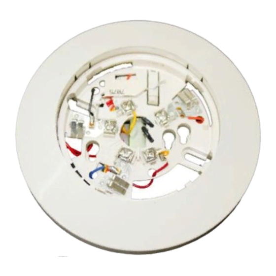
B404B Plug-in Detector Base
For use with 1451, 2451, AND 2451TH detectors
Specifications
Base Diameter:
Base Height:
Weight:
Operating Temperature Range:
Operating Humidity Range:
Electrical Ratings - includes base and detector
System Voltage:
Relay Contact Ratings
Resistive or Inductive (60% power factor) load
Form A:
Form C:
(If used, the RA400 Remote Lamp operates within the specified detector system voltage.)
Start-up Time:
(After 60 second reset)
Before Installing
Please thoroughly read the System Sensor manual I56-407,
Guide for Proper Use of System Smoke Detectors. This man-
ual provides detailed information on detector spacing,
placement, zoning, wiring, and special applications, and is
available at no charge from System Sensor. (For installation
in Canada, refer to CAN/ULC-S524, Standard for the
Installation of Fire Alarm Systems and CEC Part 1, Sec. 32.)
NOTICE: This manual should be left with the owner/user
of this equipment.
IMPORTANT: The detector used with this base must be
tested and maintained regularly following NFPA 72 require-
ments. The detector should be cleaned at least once a year.
D450-04-00
6.2 inches (15.7 cm)
0.95 inches (2.9cm)
0.6 lb. (260 g)
4-inch square box with or without plaster ring. Min. depth–1.5 inches
4-inch octagon box. Min. depth–1.5 inches
3
1
⁄
-inch octagon box. Min. depth–1.5 inches
2
0° to 49°C (32° to 120°F)
10% to 93% Relative Humidity
120 VAC, 60 Hz
2.0A @ 30VAC/DC
2.0A @ 30VAC/DC
0.6A @ 110VDC
1.0A @ 125VAC
36.0 Seconds maximum
1
General Description
The B404B detector base is designed for use with System
Sensor model 2451 and 2451TH photoelectronic and 1451
ionization detector heads. The capability of plugging these
detectors into a variety of special bases makes them more
versatile than equivalent direct-wired models. Refer to the
System Sensor catalog for other available plug-in bases.
The B404B base is intended for use in 4-wire systems with
terminals provided for power, remote annunicator, and
relay connections. This base also contains a resistor to pro-
vide current limiting in the alarm state.
3825 Ohio Avenue
St. Charles, Illinois 60174
1-800-SENSOR2, FAX: 630-377-6495
I56-375-04R
Advertisement
Table of Contents

Related Manuals for System Sensor B404B


Summary of Contents for System Sensor B404B
- Page 1 System Sensor catalog for other available plug-in bases. Installation of Fire Alarm Systems and CEC Part 1, Sec. 32.) The B404B base is intended for use in 4-wire systems with NOTICE: This manual should be left with the owner/user terminals provided for power, remote annunicator, and of this equipment.
- Page 2 Base Terminals Figure 1. Base terminals: Function Remote Annunciator (+) Test Coil (+) Not used Remote Annunciator (–) RTC (–) N.O. Supervisory Relay Form A Contacts N.O. Alarm Relay N.O. Form A Initiation Contacts N.O. Alarm Relay N.C. Form C Auxiliary Contacts Mounting The detector base mounts directly to 3...
- Page 3 Figure 3. Typical wiring diagram for 120VAC detector systems: REMOTE – REMOTE – ANNUNCIATOR ANNUNCIATOR (–) (–) RELEASING RELEASING DEVICE DEVICE BLACK LEADS TRANSFORMER PRIMARY SPECIFIED BY PANEL MANUFACTURER CONTROL ALARM INITIATION LOOP PANEL NOTE: ABOVE DIAGRAM SHOWS NFPA REQUIRED WIRING OF SUPERVISED SYSTEMS.
- Page 4 Please refer to insert for the Limitations of Fire Alarm Systems Three-Year Limited Warranty System Sensor warrants its enclosed smoke detector base to be free from Sensor, Repair Department, RA #__________, 3825 Ohio Avenue, St. defects in materials and workmanship under normal use and service for a Charles, IL 60174.
Need help?
Do you have a question about the B404B and is the answer not in the manual?
Questions and answers