Table of Contents
Advertisement
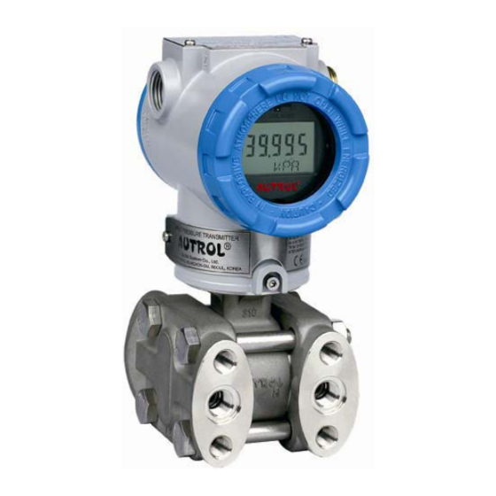
APT3100 Smart Pressure Transmitter
Operation Manual
M3100-E01G
AUTROL Series
Operation Manual : M3100-E01G
APT3100 Smart Pressure Transmitter
Operation Manual
GlobalTestSupply
* Information on this manual can be changed without an advance notice.
www.
.com
Find Quality Products Online at:
sales@GlobalTestSupply.com
Advertisement
Table of Contents

Related Manuals for Autrol APT3100


Summary of Contents for Autrol APT3100
- Page 1 APT3100 Smart Pressure Transmitter Operation Manual M3100-E01G AUTROL Series Operation Manual : M3100-E01G APT3100 Smart Pressure Transmitter Operation Manual GlobalTestSupply * Information on this manual can be changed without an advance notice. www. .com Find Quality Products Online at: sales@GlobalTestSupply.com...
-
Page 2: Table Of Contents
APT3100 Smart Pressure Transmitter Operation Manual M3100-E01G Table of Contents Chapter 1 Introduction 1.1 Using This Manual 1.2 Overview of Transmitter 1.3 Software Compatibility 1.4 Transmitter Components Chapter 2 Handling Cautions 2.1 Unpacking 2.2 Models and Specifications Check 2.3 Storage 2.4 Selecting the Installation Locations... - Page 3 APT3100 Smart Pressure Transmitter Operation Manual M3100-EO1G Chapter 5 On-line Operation 5.1 Overview 5.2 Safety Messages 5.3 Configuration Data Review 5.4 Check Output 5.5 Basic Setup 5.6 Detail Setup 5.7 Configuration of Information Variable 5.8 Configuration of Breakdown Diagnostics Function 5.9 Calibration...
-
Page 4: Chapter 1 Introduction
Model APT3100 Smart Pressure Transmitters. Chapter 5 On-line Operation Chapter 5 describes the configuration the parameter how to use variety of the Model APT3100 Smart Pressure Transmitters' software fucntion and configuration. See the following list for the details. -
Page 5: Overview Of Transmitter
Autrol® Smart Pressure Transmitter based in a microprocessor is the pressure transmitter, has a designed capacitance sensor optimized for draft measurement. APT3100 has a true draft analog range from 0 to 20mA offering that feature that a pressure range or after convert analog range to HART (Communication) digital signal transmit for control systems like DCS, PLC. -
Page 6: Transmitter Components
Operation Manual M3100-EO1G Transmitter Components The components and figure of Autrol® Smart Pressure Transmitter is suggested on the next page. Follow the precedure described on figure 1-1, 1-2, 1-3, 1-4, 1-5, 1-6. Figure 1-1. Model APT3100 Transmitter Exposed View (Housing) Figure 1-2. - Page 7 APT3100 Smart Pressure Transmitter Operation Manual M3100-EO1G Figure 1-3. Model APT3100 Exploded View (Sensor Module-D,G,L) Figure 1-4. TRANSMITTER COMPONENTS GlobalTestSupply Duon System Co.,Ltd. www. .com Find Quality Products Online at: sales@GlobalTestSupply.com...
- Page 8 APT3100 Smart Pressure Transmitter Operation Manual M3100-EO1G Figure 1-5. Model APT3100 Exploded View (Sensor Module-H) Figure 1-6. TRANSMITTER COMPONENTS GlobalTestSupply Duon System Co.,Ltd. www. .com Find Quality Products Online at: sales@GlobalTestSupply.com...
-
Page 9: Chapter 2 Handling Cautions
APT3100 Smart Pressure Transmitter Operation Manual M3100-EO1G Chapter 2 Handling Cautions This chapter consists of cautions for transmitter handling and storage, selection of installation locations, insulation and explosion structure, etc. [Quick Reference Manual] Step Job Details Instrument Unpacking - Unpack transmitter packing... -
Page 10: Unpacking
APT3100 Smart Pressure Transmitter Operation Manual M3100-EO1G 2.1 Unpacking When moving the transmitter to the installation site, keep it in its original packaging. Then, unpack the transmitter there to avoid damage on the way. 2.2 Models and Specifications Check The model name and specifications are indicated on the nameplate to the case. Please check your specification and wanted model. -
Page 11: Calibration On Spot After Installation
APT3100 Smart Pressure Transmitter Operation Manual M3100-EO1G 2.5 Calibration on Spot after Installation (1) Sensor Zero Trim should be done after transmitter is installed on spot, because zero point is not accurate as to mounting status. (2) For Sensor Zero Trim, make differential pressure of transmitter for zero in advance. Then, make Sensor Zero Trim after pressure is sufficiently stabilized (after approximately 10 seconds). -
Page 12: Insulation Resistance Test And Dielectric Strength Test
APT3100 Smart Pressure Transmitter Operation Manual M3100-EO1G 2.9 Insulation Resistance Test and Dielectric Strength Test Since the transmitter has undergone insulation resistance and dielectric strength tests at the factory before shipment, normally these tests are not required. However, if required, observe the following precautions in the test procedures. -
Page 13: Installation Of Explosion Protected Type Transmitters
2.10 Installation of Explosion Protected Type Transmitters 2.10.1 KOSHA Certification Caution for KOSHA Flameproof is following type. [Note1] Model APT3100 diaphragm sealed for potentially explosive atmosphere: Type of Protection and Marking Code: Ex d ⅡC T6 Temperature Class: T6 Ambient Temperature: -20 ~ 60'C Process Temperature: Max. - Page 14 Supply Voltage : 42 Vdc Max Output Signal : 4 to 20 mA + HART Note 3. Electrical Connection : 2 x 1/2-14NPT Female Note 4. APT3100 ATEX Certification is according to the below standards EN 60079-0 : 2006 EN 60079-1 : 2007 Note 5.
- Page 15 APT3100 Smart Pressure Transmitter Operation Manual M3100-EO1G Nonsparking Equipment for class I, Zone 2 : Ex nA IIC T4 Enclosure : Type 4X, IP66 Ambient Temperature : -20 to 60 °C Supply Voltage : 42V dc max. Output Signal : 4 to 20mA + HART®...
-
Page 16: Emc Conformity Standards
DUON System recommends customer to apply the Metal Conduit Wiring or to upset he twisted pair Shield Cable for signal wiring to conform the requirement of EMC Regulation, when customer installs AUTROL Series Transmitters to the plant. GlobalTestSupply Duon System Co.,Ltd. -
Page 17: Chapter 3 Transmitter Functions
M3100-EO1G Chapter 3 Transmitter Functions 3.1 Overview This Chapter contains information on operating Model APT3100. Tasks that should be performed on the bench priori to installation are explained in this chapter. 3.2 Safety Message Procedures and instructions in this chapter may require special precautions to ensure the safety of the personal performing the operations. - Page 18 APT3100 Smart Pressure Transmitter Operation Manual M3100-EO1G Fail Mode Select Jumper Switch has in LCD Module and Main CPU Module and Jumper Switch Line is connected circuital. In case of Not LCD Module, we can use CPU Module's Fail Mode Select Jumper Switch and In case of LCD Module we can use LCD Module's Jumper Switch.
-
Page 19: Eeprom-Write Enable And Disable Mode Switch
APT3100 Smart Pressure Transmitter Operation Manual M3100-EO1G Fail Mode Select Jumper Switch Figure 3-2 Fail Mode Selection Jumper Switch of LCD Module 3-5. EEProm-Write Enable / Disable Mode Switch There is the EEPROM (Electrically Erasable Programmable ROM) restoring various configuration variables in Transmitter. -
Page 20: Configuration Of Alarm And Security Jumper Procedures
APT3100 Smart Pressure Transmitter Operation Manual M3100-EO1G There are two security methods in APT3100. Following this. (1) Security Jumper: protect to writing configuration parameters of transmitter. (2) Physical removing Zero and Span Magnetic Buttons of Transmitter: you are not able to regulate Zero and Span in Local. - Page 21 APT3100 Smart Pressure Transmitter Operation Manual M3100-EO1G (2) Zero Configurations Set the current process value for Lower Range Value (4 mA). Put purposed pressure for zero over 10 seconds and push Zero Button over 5 seconds. Then show “Zero” in LCD window. After checking this message, take off the finger from the button. Push the button over 3 seconds after 1 second passes.
- Page 22 APT3100 Smart Pressure Transmitter Operation Manual M3100-EO1G (1) Moving between menus : Zero (2) Enter or moving to sub menu : Span (3) Moving to top menu : Zero+Span Put the button for 3 seconds to execute each function. After 3 seconds to put the ZERO+SPAN button, LCD Display will be changed from Menu to Trim.
- Page 23 APT3100 Smart Pressure Transmitter Operation Manual M3100-EO1G Exercises for each function ZERO TRIM - Executing the menu to put ZERO+SPAN button. - Moving to the sub directory to put Span button when 1 TRIM message appear. - Executing Zero Trim Function to put the Span button when 11 Z-TRIM message appear.
- Page 24 APT3100 Smart Pressure Transmitter Operation Manual M3100-EO1G Change Upper Range Value - Executing the menu to put Zero+Span button. - Moving to the next menu to put Zero button when 1 TRIM message appear. - Moving to the sub directory to put Span button when 2 Setup message appear.
- Page 25 APT3100 Smart Pressure Transmitter Operation Manual M3100-EO1G When Decimal Place function excuted, the type of decimal place will be appear on the secondline of LCD as below. Display Explanation Max. Value Remark Target value will be displayed AUTO 99999 automatically (Former Display Type)
-
Page 26: Shop Commissioning Using Hht
APT3100 Smart Pressure Transmitter Operation Manual M3100-EO1G 3.8 Shop Commissioning using HHT Commissioning consists of testing the transmitter, testing the loop, and verifying transmitter configuration data. APT-3100 Pressure Transmitter may be commissioned using HHT of HART supported either before of after installation. -
Page 27: Chapter 4 Installation
APT3100 Smart Pressure Transmitter Operation Manual M3100-EO1G Chapter 4 Installation 4.1 Overview The information in this chapter 4 covers installation considerations. Dimensional drawings for Model APT-3100 variation and mounting configuration are included in this chapter. 4.2 Safety Message Procedures and instructions in this chapter may require special precautions ensure the safety of the personnel performing the operation. -
Page 28: Commissioning On The Bench With Hand-Held Terminal
APT3100 Smart Pressure Transmitter Operation Manual M3100-EO1G 4.4 Commissioning on the bench with Hand-Held Terminal After and before installation, You can handle upon commissioning. However, for correctly handling and knowing the function, before installation you have to handle upon commissioning on the bench with Hand-Held Terminal. -
Page 29: General Considerations
APT3100 Smart Pressure Transmitter Operation Manual M3100-EO1G 4.5 General Considerations This transmitter uses the capacitive pressure sensor. If it changes the pressure sensor, capacitive pressure is changed minutely. It transfer electrical signal minutely to 4~20mA analog signal. Thus mount the transmitter close to the process and use a minimum of piping to achieve best accuracy. - Page 30 APT3100 Smart Pressure Transmitter Operation Manual M3100-EO1G that is suitable like that temperature. (4) You have to use suitable wire, cable in environment like oil, solvent, toxic gas or liquid. (5) Terminal process of lead line must use to not soldered terminal lug. Recommend isolating lead end terminal using contract tube.
- Page 31 APT3100 Smart Pressure Transmitter Operation Manual M3100-EO1G Local Indicator Ampere Meter DCS or Power Supply Figure 4-3 Picture of Terminal Board of Transmitter GlobalTestSupply Duon System Co.,Ltd. www. .com Find Quality Products Online at: sales@GlobalTestSupply.com...
- Page 32 ◈ Both transmitter covers must be fully engaged to meet explosion proof requirements A. Loop Configuration AUTROL Series Transmitters use a two-wire system for power supply, 4~20mA analog signal transmission and HART digital transmission. DC Power Supply is required for the transmitter loop. The Transmitter and distributor are connected as shown below.
- Page 33 APT3100 Smart Pressure Transmitter Operation Manual M3100-EO1G (3) Intrinsical Safety Type [Figure 4-3 Connection between Transmitter and Power Supply] B. Wiring Installation (1) General-use Type and intrinsically Safe Type Make cable wiring using metallic conduit or Waterproof cable glands. o. Apply a non-hardening...
- Page 34 APT3100 Smart Pressure Transmitter Operation Manual M3100-EO1G [Figure 4-4b Typical Wiring using Flameproof Packing Adapter] (b) Flameproof metal conduit wiring (Figure 4-4c) ◇ A seal fitting must be installed near the terminal box connections port for a sealed construction. ◇ Apply a non-hardening sealant to the threads of the...
- Page 35 APT3100 Smart Pressure Transmitter Operation Manual M3100-EO1G 4.7.5 Grounding (a) Grounding should satisfy KS requirements (grounding resistance, 10 Ohm or less). Grounding is required below 10 Ohm for explosionproof and intrinsic safety. [Note] In case of with Built-in Lightening Protector, Grounding should satisfy Special KS requirements (grounding resistance, 10 Ohm or less) (b) There are ground terminal on the inside and outside of the terminal box.
- Page 36 APT3100 Smart Pressure Transmitter Operation Manual M3100-EO1G 4.7.6 Power Supply Voltage and Load Resistance When configuring the loop, make sure that the external load resistance is within the range in the figure below. Since the voltage of transmitter terminal input is same as follows.
-
Page 37: Mechanical Considerations
APT3100 Smart Pressure Transmitter Operation Manual M3100-EO1G 4.8 Mechanical Considerations Figure 4-3 is transmitter dimensional drawings of APT3100. A mounting example and dimensional drawings is shown in Figure 4-4. Figure 4-6. Model APT3100 Outline Dimension Drawing GlobalTestSupply Duon System Co.,Ltd. - Page 38 APT3100 Smart Pressure Transmitter Operation Manual M3100-EO1G Figure 4-7. Typical Bracket Mounting GlobalTestSupply Duon System Co.,Ltd. www. .com Find Quality Products Online at: sales@GlobalTestSupply.com...
-
Page 39: Environmental Considerations
APT3100 Smart Pressure Transmitter Operation Manual M3100-EO1G 4.8.1 Mounting To use the cadence carrier from the environment where the vibration is heavy and must install the transmitter. In the environment where the vibration is heavy you will have to install the transmitter by using an assistant support. -
Page 40: Chapter 5 On-Line Operation
Chapter 5 On-line Operation 5.1 Overview This chapter describes to configure function of APT3100 SMART Pressure Transmitter. Transmitter can be configured to On-Line or Off-Line mode. In On-Line Configuration Mode, you must connect configuration such as HHT (Hand Held Terminal), etc. Configuration data inputs in Working Register of HHT and this data is sent to corresponding transmitter. -
Page 41: Check Output
APT3100 Smart Pressure Transmitter Operation Manual M3100-EO1G 5.4 Check Output Before other handle transmitter to on-line, you must examine and confirm whether transmitter currently operate and suitably configure progress variable. 5.4.1 Process Variable We use two progress variable in APT-3100 SMART Pressure Transmitter pressure value is Primary Variable and temperature value of pressure value configure SV(Secondary Variable) with fixed value. -
Page 42: Configuration Of Information Variable
APT3100 Smart Pressure Transmitter Operation Manual M3100-EO1G [ Graph of Damping Second ] Meaning Damping time is to reach 63.2% of target value 5.7 Configuration of Information Variable 5.7.1 Set Tag Tag variable is better easy method to classify to transmitter in multi transmitter install environment. -
Page 43: Calibration
APT3100 Smart Pressure Transmitter Operation Manual M3100-EO1G 5.9 Calibration Scaled system implement by calibrating the transmitter. Trim function have several function for the calibration. Smart transmitters operate differently than analog transmitter. A Smart transmitter uses a microprocessor that contains information about the sensor's specific characteristics in response to pressure and temperature inputs for calculating Process Variable. -
Page 44: Chapter 6 Maintenance
APT3100 Smart Pressure Transmitter Operation Manual M3100-EO1G Chapter 6 Maintenance 6.1 Overview This chapter describes breakdown diagnostic and maintenance. 6.2 Safety Message When operation, it requires specially notice for the safety of operator. Information that raises potential safety issues is indicated by a warning symbol(▲). Refer to the following safety messages before performing an operation proceeded by this symbol. -
Page 45: Hardware Diagnosis
APT3100 Smart Pressure Transmitter Operation Manual M3100-EO1G 6.3 Hardware Diagnostics If you suspect a malfunction despite the absence of any diagnostic messages on the HHT follow Table 6-1 described here to verify that transmitter hardware and process connections are in good working order. -
Page 46: Hardware Maintenance
M3100-EO1G 6.4 Hardware Maintenance Autrol APT3100 Smart Transmitters have no moving parts and require a minimum of scheduled maintenance. Both transmitters feature modular design for easy maintenance. If you suspect a malfunction, check for an external cause before performing the diagnostics as discussed later in this section. - Page 47 APT3100 Smart Pressure Transmitter Operation Manual M3100-EO1G 6.4.2 Disassembling the Electronics Housing The transmitter is designed with dual-compartment housing; one contains the electronics module, and the other contains all wiring terminals and the communication receptacles. Wiring Electronic Terminal Module [Figure 6.2 Structure of Housing] 6.4.2.1 Disassembling Electronics Module...
- Page 48 APT3100 Smart Pressure Transmitter Operation Manual M3100-EO1G CPU & Power Module Analog Connector Power(24Vdc) Connector Figure 6.3 Structure of Electronics Module inner Transmitter 6.4.2.2 Fail Mode and Jumper Switch of EEPROM-write Fail-mode and jumper switch of EEPROM-write is located front of electronics module(Refer to Figure 2-2, 2-3) 6.4.3 Assembling the Electronics Housing...
- Page 49 APT3100 Smart Pressure Transmitter Operation Manual M3100-EO1G Appendix I APT3100 SMART PRESSURE TRANSMITTER LCD DISPLAY CODE Message Description Remarks ADJ-U Out of Zero setting value when Zero Adj function using button(Upper side) ADJ-L Out of Zero setting value when Zero Adj function using...
- Page 50 APT3100 Smart Pressure Transmitter Operation Manual M3100- E01B Message Description Remarks -AC- Analog EEPROM Whole Write Done S-FL Sensor Fail S-OP Sensor Overpressure AEP-RF Analog EEPROM read checksum error TS-FL Temperature Sensor Error AEP-WF Analog EEPROM write fail EOSC Crystal Element Defect Alarm...
Need help?
Do you have a question about the APT3100 and is the answer not in the manual?
Questions and answers