Autrol APT 3200 Instruction Manual
Smart pressure transmitter
Hide thumbs
Also See for APT 3200:
- Operating manual (38 pages) ,
- Operation manual (58 pages) ,
- Operation manual (56 pages)

Related Manuals for Autrol APT 3200


Summary of Contents for Autrol APT 3200
- Page 1 PT 3200 Smart Pressure Transmitter Instruction Manual Document Number: IM-APT3200 www.autroltransmitters.com...
- Page 2 Before handling APT3200 transmitter, all users have to be fully aware of it. Information on this manual can be changed Without an advance notice. Autrol Corporation of America 796 Tek Drive, Crystal Lake, IL 60014, USA Tel: +1 847-857-6062, +1 857-779-5000...
-
Page 3: Table Of Contents
Table of Contents Chapter 1 Introduction………………………………………………………………………………………………………………………4 1.1 Using This Manual…………………………………………………………………………………………………………………………..4 Chapter 2 Handling Cautions………………………………………………………………………………………………………………………………4 Chapter 3 Transmitter Functions………………………………………………………………………………………………………………………..4 Chapter 4 Installation…………………………………………………………………………………………………………………………………………4 Chapter 5 On-line Operation………………………………………………………………………………………………………………………………4 Chapter 6 Maintenance………………………………………………………………………………………………………………………………………4 1.2 Overview of Transmitter………………………………………………………………………………………………………………….5 1.3 Software Compatibility……………………..............…………………………….5 1.4 Transmitter Components........................6 Chapter 2 Handling Cautions........................7 2.1 Unpacking............................8 2.2 Models and Specifications Check......................8... - Page 4 4.1 Overview ............................23 4.2 Safety Message ..........................23 4.3 Warning ............................23 4.4 Commissioning on the bench with Hand-Held Terminal...............24 4.5 General Considerations........................25 4.6 Electrical Considerations (Power Supply).....................25 4.6.1 Power Supply..............................25 Max. Loop Resistance [Ω] = (E-11.9) [vdc] / 0.022 [mA].....................25 4.7 Wiring..............................25 4.7.1 Caution of Wiring............................
- Page 5 5.8 Diagnostics and Services........................37 5.8.1 Loop Test..............................37 5.9 Calibration............................38 5.9.1 Sensor Trim..............................38 5.9.2 DA (Digital to Analog) Trim..........................38 Chapter 6 Maintenance..........................39 6.1 Overview .............................39 6.2 Safety Message............................39 6.2.1 Warning..............................39 6.3 Hardware Diagnostics..........................40 6.4 Hardware Maintenance ........................41 6.4.1 Test Terminals............................
-
Page 6: Chapter 1 Introduction
Using This Manual The Chapters in this operating manual provide information on installing, operating, and maintaining devices from the AUTROL Model APT3200 Smart Pressure Transmitter. The Chapters are organized as follows. Chapter 2 Handling Cautions This chapter consists of core information for installing APT3200 on operating place after buying it. -
Page 7: Overview Of Transmitter
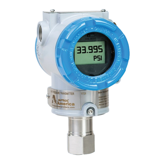
Overview of Transmitter Autrol® Smart Pressure Transmitter based in a microprocessor is the pressure transmitter, has a designed capacitance sensor optimized for draft measurement. APT-3200 has a true draft analog range from 0 to 20mA offering that feature that a pressure range or after convert analog range to HART (Communication) digital signal transmit for control systems like DCS, PLC. -
Page 8: Transmitter Components
Transmitter Components The components and figure of Autrol® Smart Pressure Transmitter is suggested on the next page. Follow the procedure described on figure 1-1. [Figure 1-1 Transmitter Exposed View and Components] www.autroltransmitter.com... -
Page 9: Chapter 2 Handling Cautions
Chapter 2 Handling Cautions This chapter consists of cautions for transmitter handling and storage, selection of installation locations, insulation and explosion structure, etc. [Quick Reference Manual] Step Job Details Instrument Unpacking - Unpack transmitter packing Model and - Make sure whether the delivered transmitter is same Specifications as options attached on its nameplate Check... -
Page 10: Unpacking
2.1 Unpacking When moving the transmitter to the installation site, keep it in its original packaging. Then, unpack the transmitter there to avoid damage on the way. 2.2 Models and Specifications Check The model name and specifications are indicated on the nameplate to the case. Please check your specification and wanted model. -
Page 11: Calibration On Spot After Installation
(3) Shock and Vibration Select an installation site suffering minimum shock and vibration (although the transmitter is designed to be relatively resistant to shock and vibration) (4) Installation of Explosion-protected Transmitters Explosion-protected transmitters can be installed in hazardous areas according to the gas types for which they are certified. -
Page 12: Restrictions On Use Of Radio Transceivers
2.8 Restrictions on Use of Radio Transceivers ▲ Warning ◈ Although the transmitter has been designed to resist high frequency electrical noise, if a radio transceiver is used near the transmitter of its external wiring, the transmitter may be affected by high frequency noise pickup. -
Page 13: Installation Of Explosion Protected Type Transmitters
2.10 Installation of Explosion Protected Type Transmitters 2.10.1 KOSHA Certification Caution for KOSHA Flameproof is following type. [Note1] Model APT3100 diaphragm sealed for potentially explosive atmosphere: Type of Protection and Marking Code: Ex d ⅡC T6 Temperature Class: T6 ... -
Page 14: Emc Conformity Standards
EMS (Immunity): EN50082-2 DUON System recommends customer to apply the Metal Conduit Wiring or to upset he twisted pair Shield Cable for signal wiring to conform the requirement of EMC Regulation, when customer installs AUTROL Series Transmitters to the plant. www.autroltransmitter.com... -
Page 15: Chapter 3 Transmitter Functions
3.4 Fail Mode Alarm AUTROL® Smart Pressure Transmitter automatically and continuously performs self-diagnostic routines. If the self-diagnostic routines detect a failure, the transmitter drives its output outside of the normal saturation values. The transmitter will drive its output low(down) or high(up) based on the position of the failure mode alarm jumper . - Page 16 [Table 3-1 Standard Alarm and Saturation Value] Level 4~20mA Saturation 4~20mA Alarm Low/Down 3.9 mA ≤ 3.75 mA High/Up 20.8 mA ≥ 21.75 mA Fail Mode Select Jumper Switch has in LCD Module and Main CPU Module and Jumper Switch Line is connected circuital.
-
Page 17: Eeprom-Write Enable / Disable Mode Switch
Fail Mode Select Jumper Switch [Figure 3-2 LCD Module’s Fail Mode Select Jumper] 3.5 EEPROM-Write Enable / Disable Mode Switch There is the EEPROM (Electrically Erasable Programmable ROM) restoring various configuration variables in Transmitter. For protect to change configuration variable data in software, hardware side there is Write-Protect Mode and Jumper Switch selected it segmented "EEP-Write DIS / EN "... -
Page 18: Security Jumper (Eeprom Write Protect)
There are two security methods in APT3200. Following this. (1) Security Jumper: protect to writing configuration parameters of transmitter. (2) Physical removing Zero and Span Magnetic Buttons of Transmitter: you are not able to regulate Zero and Span in Local. [Notification] If EEP-Write is not connected, it is classified Security Off state. - Page 19 “Zero” in LCD window. After checking this message, take off the finger from the button. Push the button over 3 seconds after 1 second passes. Then show “-ZE-“ in LCD window. By this message, all zero configurations have finished. If the works has failed, show “SPEr” or “SEtE” in LCD window. (3) Span Configurations Set the current process value for Upper Range Value (20 mA).
- Page 20 • Put the button for 3 seconds to execute each function. After 3 seconds to put the ZERO+SPAN button, LCD Display will be changed from Menu to Trim. To see next menu, put the Zero Button for 3 seconds and then Setup Menu will be displayed. Use Zero button to move down to the next directory. •...
- Page 21 Zero Adjustment : To change the PV value as 14 - Executing the menu to put ZERO+SPAN button. - Moving to the sub directory to put Span button when 1 TRIM message appear. - Moving to the sub directory to put Zero button when 11 Z-TRIM message appear. - Executing Zero Adjustment function to put Span button when 12 Z-ADJ message appear.
- Page 22 Change Lower Range Value - Executing the menu to put Zero+Span button. - Moving to the next menu to put Zero button when 1 TRIM message appear. - Moving to the sub directory to put Span button when 2 Setup message appear. - Moving to the next menu to put Zero button when 21 Unit message appear.
- Page 23 Zero/Span Button [Figure 3-4 Transmitter’s Zero/Span configuration Button] www.autroltransmitter.com...
-
Page 24: Commissioning On The Bench Using Hht
3.8 Commissioning on the bench using HHT Commissioning consists of testing the transmitter, testing the loop, and verifying transmitter configuration data. APT-3100 Pressure Transmitter may be commissioned using HHT of HART supported either before of after installation. ▲ If you connect "TEST" pin, it's not communicated. If it doesn't exposed electronics circuits after install, you must connect all Jumper of transmitter in the shop commissioning level. -
Page 25: Chapter 4 Installation
Chapter 4 Installation 4.1 Overview The information in this chapter 4 covers installation considerations. Dimensional drawings for Model APT-3100 variation and mounting configuration are included in this chapter. 4.2 Safety Message Procedures and instructions in this chapter may require special precautions ensure the safety of the personnel performing the operation. -
Page 26: Commissioning On The Bench With Hand-Held Terminal
4.4 Commissioning on the bench with Hand-Held Terminal After and before installation, You can handle upon commissioning. However, for correctly handling and knowing the function, before installation you have to handle upon commissioning on the bench with Hand-Held Terminal. Start want Bench Calibration? -
Page 27: General Considerations
4.5 General Considerations This transmitter uses the Piezo-Resistive pressure sensor. If it changes the pressure sensor, capacitive pressure is changed minutely. It transfer electrical signal minutely to 4~20mA analog signal. Thus mount the transmitter close to the process and use a minimum of piping to achieve best accuracy. However keep in mind the need for easy access, safety of personnel, practical field calibration, and a suitable transmitter environment. -
Page 28: Selecting The Wiring Materials
4.7.2 Selecting the Wiring Materials (1) Use over 600V PVC shielded wire or standard lead line of same class or cable. (In order to ensure proper communication use 24 AWG or lager wire, and do not exceed 1500 meters.) (2) Use the shielded wire in electrical noise effected area. (3) At the higher or lower temperature area than ambient temperature it uses the wire or the cable that is suitable like that temperature. -
Page 29: Wiring
◈ Both transmitter covers must be fully engaged to meet explosion proof requirements A. Loop Configuration AUTROL Series Transmitters use a two-wire system for power supply, 4~20mA analog signal transmission and HART digital transmission. DC Power Supply is required for the transmitter loop. The Transmitter and distributor are connected as shown below. -
Page 30: Wiring Installation
(2) Explosionproof Type (3) Intrinsically Safety Type: Safety barrier should be connected within the loop B. Wiring Installation (1) General-use Type and intrinsically Safe Type Make cable wiring using metallic conduit or Waterproof cable glands. o. Apply a non-hardening sealant to the terminal box connection port and the threads on the flexible metal conduit... - Page 31 (2) KOSHA Flameproof Type Wire cables through a flameproof packing adapter, or using a flameproof metal conduit. (a) Wiring cable through flameproof packing adapter for KOSHA flameproof type (see Figure 4-4b) ◇ Use only flameproof packing adapter by KOSHA. ◇ Apply a non-hardening sealant to the terminal box connection port and to the threads on the flameproof packing adapter for waterproofing ◇...
- Page 32 (b) Flameproof metal conduit wiring (Figure 4-4c) ◇ A seal fitting must be installed near the terminal box connections port for a sealed construction. ◇ Apply a non-hardening sealant to the threads of the terminal box connection box, flexible metal conduit and deal fitting for waterproofing.
-
Page 33: Grounding
4.7.5 Grounding (a) Grounding should satisfy KS requirements (grounding resistance, 10 Ohm or less). Grounding is required below 10 Ohm for explosionproof and intrinsic safety. [Note] In case of with Built-in Lightening Protector, Grounding should satisfy Special KS requirements (grounding resistance, 10 Ohm or less) (b) There are ground terminal on the inside and outside of the terminal box. -
Page 34: Power Supply Voltage And Load Resistance
4.7.6 Power Supply Voltage and Load Resistance When configuring the loop, make sure that the external load resistance is within the range in the figure below. Since the voltage of transmitter terminal input is same as follows. General Standard: 11.9 to 45 Vdc ... -
Page 35: Mechanical Considerations
4.8 Mechanical Considerations Figure 4-3 is transmitter dimensional drawings of APT3200. A mounting example and dimensional drawings is shown in Figure 4-4. 112 mm 86 mm 73 mm 39 mm [Figure 4-3 Transmitter Outline Dimensional Drawings] [Figure 4-4 Typical Bracket Mounting Example] www.autroltransmitter.com... -
Page 36: Mounting
4.8.1 Mounting To use the cadence carrier from the environment where the vibration is heavy and must install the transmitter. In the environment where the vibration is heavy you will have to install the transmitter by using an assistant support. In the case of severe vibration, promote to mount on pipe using a mounting bracket as option. -
Page 37: Chapter 5 Online Operation
Chapter 5 Online Operation 5.1 Overview This chapter describes to configure function of APT3200 SMART Pressure Transmitter. Transmitter can be configured to On-Line or Off-Line mode. In On-Line Configuration Mode, you must connect configuration such as HHT (Hand Held Terminal), etc. Configuration data inputs in Working Register of HHT and this data is sent to corresponding transmitter. -
Page 38: Process Variable
Before other handle transmitter to on-line, you must examine and confirm whether transmitter currently operate and suitably configure progress variable. 5.4.1 Process Variable We use two progress variable in APT-3200 SMART Pressure Transmitter pressure value is Primary Variable and temperature value of pressure value configure SV (Secondary Variable) with fixed value. -
Page 39: Configuration Of Information Variable
[ Graph of Damping Second ] 5.7 Configuration of Information Variable 5.7.1 Set Tag Tag variable is better easy method to classify to transmitter in multi transmitter install environment. Tag Character can be used to 8 word of English/number. 5.7.2 Set Messages When use several transmitter, user can define for classification each transmitter and use 32 words of English/number. -
Page 40: Calibration
5.9 Calibration Scaled system implement by calibrating the transmitter. Trim function have several function for the calibration. Smart transmitters operate differently than analog transmitter. A Smart transmitter uses a microprocessor that contains information about the sensor's specific characteristics in response to pressure and temperature inputs for calculating Process Variable. -
Page 41: Chapter 6 Maintenance
Chapter 6 Maintenance 6.1 Overview This chapter describes breakdown diagnostic and maintenance. 6.2 Safety Message When operation, it requires specially notice for the safety of operator. Information that raises potential safety issues is indicated by a warning symbol (▲). Refer to the following safety messages before performing an operation proceeded by this symbol. -
Page 42: Hardware Diagnostics
6.3 Hardware Diagnostics If you suspect a malfunction despite the absence of any diagnostic messages on the HHT follow Table 6-1 described here to verify that transmitter hardware and process connections are in good working order. If you suspect a malfunction despite the absence of any diagnostic messages on the HHT follow Table 6-1 described here to verify that transmitter hardware and process connections are in good working order. -
Page 43: Hardware Maintenance
6.4 Hardware Maintenance Autrol APT3200 Smart Transmitters have no moving parts and require a minimum of scheduled maintenance. Both transmitters feature modular design for easy maintenance. If you suspect a malfunction, check for an external cause before performing the diagnostics as discussed later in this section. -
Page 44: Disassembling The Electronics Housing
6.4.2 Disassembling the Electronics Housing The transmitter is designed with dual-compartment housing; one contains the electronics module, and the other contains all wiring terminals and the communication receptacles. Wiring Electronic Terminal Module [Figure 6.2 Structure of Housing] 6.4.2.1 Disassembling Electronics Module Use the following procedure to remove the electronics module. -
Page 45: Fail Mode And Jumper Switch Of Eeprom-Write
CPU & Power Module Analog Connector Power(24Vdc) Connector Figure 6.3 Structure of Electronics Module inner Transmitter 6.4.2.2 Fail Mode and Jumper Switch of EEPROM-write Fail-mode and jumper switch of EEPROM-write is located front of electronics module (Refer to Figure 2-2, 2-3) 6.4.3 Assembling the Electronics Housing Re-assembling procedure is same as follows. -
Page 46: Apt3200 Smart Pressure Transmitter
Appendix I APT3200 SMART PRESSURE TRANSMITTER LCD DISPLAY CODE Message Description Remarks ADJ-U Out of Zero setting value when Zero Adj function using button (Upper side) ADJ-L Out of Zero setting value when Zero Adj function using Button (Lower side) ZERO Initial message in using Zero button SPAN... - Page 47 Message Description Remarks -AC- Analog EEPROM Whole Write Done S-FL Sensor Fail S-OP Sensor Overpressure AEP-RF Analog EEPROM read checksum error TS-FL Temperature Sensor Error AEP-WF Analog EEPROM write fail EOSC Crystal Element Defect Alarm FAVE Flash Access Violation ADC-FL ADC INITIAL ERROR www.autroltransmitter.com...
- Page 48 AUTROL®, AUTROL™ are trade mark of smart transmitter brand series to measure Pressure, Temperature and Level, which is manufactured & owned by DUON System Co., Ltd(hereafter DUON) since 1989. AUTROL®, AUTROL™ series also provide services of electric appliance installation, repair of electric, magnetic measuring instruments,...
Need help?
Do you have a question about the APT 3200 and is the answer not in the manual?
Questions and answers