
Subscribe to Our Youtube Channel
Related Manuals for Panduit ATLONA AT-UHD-PRO3-1616M


Summary of Contents for Panduit ATLONA AT-UHD-PRO3-1616M
- Page 1 4K/UHD 16x16 HDMI to HDBaseT Matrix Switcher Atlona Manuals AT-UHD-PRO3-1616M Switchers...
- Page 2 Version Information Version Release Date Notes Nov 2018 New format Jul 2019 Added missing IR remote control unit documentation Feb 2020 Added missing factory reset procedure Jul 2020 Removed IR remote control unit - no longer included AT-UHD-PRO3-1616M...
- Page 3 Welcome to Atlona! Thank you for purchasing this Atlona product. We hope you enjoy it and will take a extra few moments to register your new purchase. Registration only takes a few minutes and protects this product against theft or loss. In addition, you will receive notifications of product updates and firmware.
- Page 4 Atlona, Inc. (“Atlona”) Limited Product Warranty Coverage Atlona warrants its products will substantially perform to their published specifications and will be free from defects in materials and workmanship under normal use, conditions and service. Under its Limited Product Warranty, Atlona, at its sole discretion, will either: •...
- Page 5 Atlona, Inc. (“Atlona”) Limited Product Warranty • Damage, deterioration or malfunction resulting from the installation or removal of this product from any installation, any unauthorized tampering with this product, any repairs attempted by anyone unauthorized by Atlona to make such repairs, or any other cause which does not relate directly to a defect in materials and/or workmanship of this product.
- Page 6 Safety and Certification CAUTION 10. Protect the power cord from being walked on or pinched particularly at plugs, convenience receptacles, and the point RISK OF ELECTRIC SHOCK DO NOT OPEN where they exit from the product. CAUTION: TO REDUCT THE RISK OF 11.
-
Page 7: Table Of Contents
Table of Contents Introduction Features Package Contents Panel Description Front Rear Installation Audio Connectors Connection Instructions Setting the IP Mode Connection Diagram Basic Operation Powering the Matrix Standby Mode Viewing Matrix Settings Viewing the current routing state Displaying the System Settings Resetting to Factory Defaults Routing Inputs to Outputs Single Input-to-Output Routing... - Page 8 Table of Contents Firmware page Network page Control page Users page I/O page Route Memory page EDID page HDCP page HDBT Test page Audio page Appendix Updating the Firmware Cable Termination HDBaseT Testing Default Settings Mounting Instructions Rack Installation Surface Mounting Specifications AT-UHD-PRO3-1616M...
-
Page 9: Introduction
Introduction The AT-UHD-PRO3-1616M is a 4K/UHD 16×16 HDMI to HDBaseT Matrix Switcher with PoE for 4K/UHD @ 60 Hz video signals with Power over Ethernet for receivers and analog audio breakout. The matrix provides both extended distance, 330 foot (100 meter) and long distance, 230 foot (70 meter) HDBaseT transmission over category cable. It also provides convenient bidirectional extension of both RS-232 and IR Control. -
Page 10: Panel Description
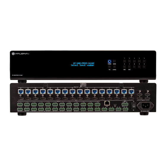
Panel Description Front POWER ENTER CANCEL EDID INFO AT-UHD-PRO3-1616M HDBaseT OUT Front Panel Display HDMI IN HDMI OUT MAIN AUDIO OUT This 16-character, two-row display provides the status of the matrix during various operations. RS-232 IR IN RX TX POWER IR IN IR OUT PWR: 100-240VAC 50/60Hz... -
Page 11: Rear
Panel Description POWER ENTER Rear CANCEL EDID INFO AT-UHD-PRO3-1616M HDBaseT OUT HDMI IN HDMI OUT AUDIO OUT MAIN RS-232 IR IN RX TX IR IN IR OUT PWR: 100-240VAC 50/60Hz HDBaseT OUT Connect up to 16 PoE-compatible receivers to these ports using Ethernet cable. HDMI IN Connect up to 16 HD/UHD source devices to these ports using HDMI cables. -
Page 12: Installation
Installation Audio Connectors The AUDIO IN and AUDIO OUT ports on the AT-UHD-PRO3-1616M provide analog inputs and outputs, respectively, for audio. Use the included 4-pin captive screw blocks to connect unbalanced analog sources/outputs. AT-UHD-PRO3-1616M... -
Page 13: Connection Instructions
Installation Connection Instructions 1. Connect up to 16 HD/UHD sources to the HDMI IN (1 - 16) ports. 2. Connect up to 16 PoE-compatible receivers (e.g. AT-UHD-EX-100CE-RX) to the HDBaseT OUT ports using Ethernet cables. NOTE: Ports 1ED through 8ED are used for extended distance connections and are capable of extending up to 330 feet (100 meters). -
Page 14: Setting The Ip Mode
Installation Setting the IP Mode The AT-UHD-PRO3-1616M is shipped with DHCP enabled. Once connected to a network, the DHCP server (if available), will automatically assign an IP address to the unit. If no DHCP server is found or available, then the matrix will be set to the following IP settings: Default IP settings Description... - Page 15 Installation Using the web GUI 1. Login to the web GUI. Refer to Introduction to the Web GUI (page 54) for more information. 2. Click Network, under the Settings section in the menu bar on the left side of the screen. •...
-
Page 16: Connection Diagram
Installation Connection Diagram ri c R SYS R SYS ri c R SYS R SYS Speakers pli fer al Am ss ion Pr ofe Zone Amplifier HD display TE R FC N AT-UHD-EX-100CE-RX -U HD AT-UHD-PRO3-1616M Set-Top Box Media Player P BOX A/V Receiver ri c... -
Page 17: Basic Operation
Basic Operation Powering the Matrix The master power button is located on the rear panel of the matrix. This rocker switch allows power to be applied to the matrix. POWER ENTER 1. Press the ON/OFF button so that it is in the ON position. To power-off the matrix, push the button to the OFF INFO CANCEL EDID... -
Page 18: Standby Mode
Basic Operation Standby Mode The POWER button on the front panel of the matrix, allows the matrix to be powered-on or placed in standby mode. In standby mode, the web GUI is still accessible, even though the unit appears “powered off”. 1. -
Page 19: Viewing Matrix Settings
Basic Operation Viewing Matrix Settings The front panel display provides the current status of the matrix and its settings. The buttons on the front panel can be used to display the current routing settings as well as network settings. Viewing the current routing state 1. -
Page 20: Displaying The System Settings
Basic Operation Displaying the System Settings 1. Make sure the home screen is displayed. If the home screen is not displayed, press the CANCEL button to return to the home screen. 2. Press and release the FNC button to display the SELECT FUNCTION screen. ... -
Page 21: Resetting To Factory Defaults
Basic Operation Resetting to Factory Defaults The following procedure will reset the AT-UHD-PRO3-1616M to factory-default settings. 1. Make sure the home screen is displayed. If the home screen is not displayed, press the CANCEL button to return to the home screen. 2. -
Page 22: Routing Inputs To Outputs
Basic Operation Routing Inputs to Outputs When the AT-UHD-PRO3-1616M is shipped from the factory, the matrix is set to “one-to-one” routing mode. This means that input 1 is routed to output 1, input 2 is routed to output 2, and so on. The following section describes how to change the routing state. - Page 23 Basic Operation Using the web GUI As in the previous example, HDMI IN 3 will be routed to ZONE OUT 4. 1. Login to the web GUI. Refer to Introduction to the Web GUI (page 54) for more information. 2. Click I/O, under the Configuration section, in the menu bar on the left side of the screen. 3.
-
Page 24: Routing A Single Input To All Outputs
Basic Operation Routing a Single Input to All Outputs Using the Front Panel This procedure will route a single input to all eight outputs. 1. Make sure the home screen is displayed. If the home screen is not displayed, press the CANCEL button to return to the home screen. - Page 25 Basic Operation Using the web GUI As in the previous example, HDMI IN 2 will be routed to all outputs. 1. Login to the web GUI. Refer to Introduction to the Web GUI (page 54) for more information. 2. Click I/O, under the Configuration section, in the menu bar on the left side of the screen. 3.
-
Page 26: Output Mirroring
Basic Operation POWER ENTER Output Mirroring CANCEL EDID INFO AT-UHD-PRO3-1616M In addition to the HDBaseT outputs, the AT-UHD-PRO3-1616M also provides four HDMI output ports (highlighted in the image below). HDBaseT OUT HDMI IN HDMI OUT MAIN AUDIO OUT RS-232 IR IN RX TX IR IN... - Page 27 Basic Operation NOTE: Name descriptors in the web GUI are different than those of the port names on the enclosure (e.g. Out 9: Output_9 = HDBaseT OUT 9), and are used interchangably in this document. Therefore, it is recommended to refer to ports by the their number, until they are changed. Refer to Input and Output Management (page 34) for more information on this topic.
-
Page 28: Disabling Mirroring
Basic Operation Disabling Mirroring When mirroring is disabled, an input can then be routed to that HDMI output. The diagram below now shows HDMI IN 2 routed to HDMI OUT 17. Note that the output on HDBaseT OUT 9 is from the source connected to HDMI IN 7, which was used when mirroring was enabled. - Page 29 Basic Operation 1. Login to the web GUI. Refer to Introduction to the Web GUI (page 54) for more information. 2. Click I/O, under the Configuration section, in the menu bar on the left side of the screen. 3. Click the Mirror Mode drop-down list, to the right of Out 17: Output_17, and select Off. 4.
-
Page 30: Creating And Editing Routing Presets
Basic Operation Creating and Editing Routing Presets Using presets provides a quick and efficient way of switching between multiple routing configurations. The AT-UHD- PRO3-1616M provides 50 memory locations that can be used to store each preset. The following section covers creating, editing, and using routing presents. -
Page 31: Recalling A Preset
Basic Operation Recalling a Preset 1. Login to the web GUI. Refer to Introduction to the Web GUI (page 54) for more information. 2. Click Route Memory, under the Configuration section, in the menu bar on the left side of the screen. 3. -
Page 32: Editing Presets
Basic Operation Editing Presets 1. Login to the web GUI. Refer to Introduction to the Web GUI (page 54) for more information. 2. Click Route Memory, under the Configuration section, in the menu bar on the left side of the screen. 3. -
Page 33: Renaming Presets
Basic Operation Renaming Presets By default, each of the 50 memory locations used for routing presets are M1 : Preset_1, M2 : Preset_2, and so on. When dealing with multiple presets, it is helpful to use more descriptive names for easy identification. 1. -
Page 34: Input And Output Management
Basic Operation Input and Output Management When dealing with multiple sources and multiple output devices, within the web GUI, it can be useful to assign descriptive names to each input and output. Renaming Inputs 1. Login to the web GUI. Refer to Introduction to the Web GUI (page 54) for more information. -
Page 35: Renaming Outputs
Basic Operation Basic Operation Renaming Outputs 1. Login to the web GUI. Refer to Introduction to the Web GUI (page 54) for more information. 2. Click I/O, under the Configuration section, in the menu bar on the left side of the screen. 3. -
Page 36: Renaming Memory Presets
Basic Operation Renaming Memory Presets The AT-UHD-PRO3-1616M provides 50 presets for storing routing presets. Each preset can also be renamed with more descriptive names, for easy identification and recall at any time. 1. Login to the web GUI. Refer to Introduction to the Web GUI (page 54) for more information. -
Page 37: Edid Management
Basic Operation EDID Management EDID is an acronym for Extended Display Identification Data. Before a source can send a picture and/or audio to a display (or other sink device), the source requests information from the display on what video and audio formats it can support. - Page 38 Basic Operation 6. Press the ENTER button to confirm the entry. 7. Press button 3 to select the INT (internal) option. input:01 mode: 1:dflt 2:saved 3:int 8. Select the desired EDID by pressing button 1 or 2. Press button 1 to move forward through the list of EDID selections.
-
Page 39: Using The Web Gui
Basic Operation Using the web GUI 1. Login to the web GUI. Refer to Introduction to the Web GUI (page 54) for more information. 2. Click EDID, under the Configuration section in the menu bar on the left side of the screen. 3. -
Page 40: Copying A Downstream Edid
Basic Operation Copying a Downstream EDID In some instances, it may be desirable to use the EDID of a connected display, and store it for later use. The AT- UHD-PRO3-1616M provide ten memory locations that can be used to store custom EDID data. Once the EDID is stored in memory, it can be copied to any input. - Page 41 Basic Operation Using the web GUI 1. Verify that a display or other sink device is connected to the output from which the EDID will be read. In this example, a display is connected to HDMI OUT 1. 2. Login to the web GUI. Refer to Introduction to the Web GUI (page 54) for more information.
- Page 42 Basic Operation 5. Click the Save button to commit changes. If the EDID is recorded successfully, then a message will be displayed indicating that the EDID was saved to the selected memory location. The stored EDID can now be copied to any of the available inputs, as shown in the illustration, below. Refer to EDID Management (page 37) for more information.
-
Page 43: Managing Users
Basic Operation Managing Users The AT-UHD-PRO3-1616M allows the Admin user to create, edit, and remove additional TCP/IP users. All users have the same level of access to control the AT-UHD-PRO3-1616M. However, only the Admin user is allowed to manage other users. Up to three additional users can be created. NOTE: Usernames and passwords are restricted to alphanumeric characters, only. - Page 44 Basic Operation 6. Once created, the new user and the associated password will appear under the All User Login Settings section. To login with the new username, click Logout in the upper-right corner of the screen, then enter the login credentials for the user on the Login page.
-
Page 45: Editing / Deleting Users
Basic Operation Editing / Deleting Users The username and password of a user can be changed using this method. 1. Open the desired web browser and enter the IP address of the AT-UHD-PRO3-1616M. 2. Log in as the Admin user with the required credentials. The factory-default username and password for the admin user are listed below: Username: root Password: Atlona... -
Page 46: Advanced Operation
Advanced Operation RS-232 Control The AT-UHD-PRO3-1616M provides RS-232 control between an automation system and an RS-232 device using a captive screw connector block. The AT-UHD-PRO3-1616M provides two modes of RS-232 control: Pass-through mode and control mode. RS-232 is serial data protocol that allows Data Terminal Equipment (DTE) devices, such a computer or control 1 2 3 4 5 system, to communicate with Data Communication Equipment (DCE) devices, such as the AT-UHD-PRO3-1616M, amplifier, or display. -
Page 47: Cable Assembly
Advanced Operation Cable Assembly When connecting a DTE device to a DCE device, a straight-through cable should be used. A straight-through cable is wired in such a way that the pins on one side of the cable are connected to the corresponding pins on the opposite side of the cable, as shown in the table below. -
Page 48: Pass-Through Mode
Advanced Operation Pass-through mode In pass-through mode, RS-232 commands are sent to the AT-UHD-PRO3-1616M and then transmitted over HDBaseT to the receiver unit (e.g. AT-UHD-100CE-RX), and then to the display (sink) device. 1. Connect the RS-232 cable between the control system and the AT-UHD-PRO3-1616M. Refer to Cable Assembly (page 47) for instructions on preparing the cable. - Page 49 Advanced Operation 4. Launch a web browser and login to the web GUI. Refer to Introduction to the Web GUI (page 54) for more information. The factory-default username and password are listed below: Username: root Password: Atlona 5. Click Control in the side menu bar. 6.
-
Page 50: Control Mode
Advanced Operation Control mode In control mode, RS-232 commands are sent from a computer or control system (DTE) to the AT-UHD-PRO3-1616M (DCE). This method allows direct control of the matrix for routing, IP configuration, powering-on / powering-off and other functions. NOTE: The RS-232 port on the AT-UHD-PRO3-1616M runs at a default baud rate of 115200. -
Page 51: Ir Control
Advanced Operation IR Control POWER ENTER The AT-UHD-PRO3-1616M feature eight IR IN ports and eight IR OUT ports. Devices at either the headend or CANCEL EDID INFO connected to the receiver unit can be controlled using IR. AT-UHD-PRO3-1616M ZONE OUT AT-UHD-PRO3-1616M HDBaseT OUT HDMI IN... -
Page 52: Controlling Display Devices
Advanced Operation Controlling Display Devices The following shows how to control displays (or other sink devices) which are connected to an HDBaseT receiver. When a control device is connected to an IR IN port, the IR signal is transmitted over Ethernet cable, from the associated ZONE OUT port, to the HDBaseT receiver. -
Page 53: Controlling Headend Devices
Advanced Operation Controlling Headend Devices Source devices (at the headend) can be controlled from the viewing location. IR control depends upon the current routing state: only the currently viewed source can be controlled using IR. 1. Connect the IR receiver (AT-IR-CS-RX) to the HDBaseT receiver, at the viewing location. Although a control system can be used, a basic IR receiver is commonly used. -
Page 54: The Web Gui
The Web GUI Introduction to the Web GUI The AT-UHD-PRO3-1616M includes a built-in web GUI. Atlona recommends that the web GUI be used to set up the matrix, as it provides intuitive management of all features. Follow the instructions below to access the webGUI. 1. - Page 55 The Web GUI 6. The Status page will be displayed. Menu Bar The window on the left side of the screen is the is the menu bar and lists all available menus. Click on the desired menu item to open that page. For example, clicking on Network will display the Network page.
-
Page 56: Status Page
The Web GUI Status page After logging in, the Status page will be displayed. The Status page provides basic information about the matrix, including the model name, software version, MAC address, and operating temperature. Model MAC Address The model (SKU) of this product. The MAC address of the unit. -
Page 57: Firmware Page
The Web GUI Firmware page This page provides information on the current firmware for the matrix and all connected UHD-EX-based HDBaseT receivers/transmitters. In addition, both matrix and transmitter/receiver (if connected) firmware can be updated here. Refer to Updating the Firmware (page 67) for more information on firmware update procedures. -
Page 58: Network Page
The Web GUI Network page System Secure (SSH) HTTP Port Secure Socket Shell. Click ON to enable this feature. Enter the HTTP listening port in this field. The default setting is OFF. Enabling this feature will disable the Telnet daemon and web server. IP Timeout Enter the timeout interval, in seconds, before the Telnet DHCP... -
Page 59: Control Page
The Web GUI Control page Power Blink LED Click ON to power-on the matrix. Click OFF to place the Click the Blink button to flash the POWER button on matrix in standby mode. Refer to Standby Mode (page the front panel. When clicked, the Blink button will read for more information on standby mode. -
Page 60: Users Page
The Web GUI Users page Username Enter the username in this field. Only alphanumeric characters are are accepted in this field. Password Enter the password for the user in this field. Only alphanumeric characters are are accepted in this field. Click this button to add a TCP/IP user. -
Page 61: I/O Page
The Web GUI I/O page I/O Reset Click this button to reset all input/output routing to factory-default settings. Out 1: Output_1 - Out 10: Output_20 Click the drop-down lists, to the right, to select the desired input for routing. Refer to Routing Inputs to Outputs (page 22) for more information. -
Page 62: Route Memory Page
The Web GUI Route Memory page Memory Reset Click this button to reset preset memory to factory-default settings. Note that performing this function will erase all memory presets. Output 1 - Output 20 Click the drop-down lists, to the right of the output name, to select the desired input for routing. Refer to Routing Inputs to Outputs (page 22) for more information. -
Page 63: Edid Page
The Web GUI EDID page EDID Reset Click this button to reset all EDID settings to the factory-default settings. Note that this will erase any stored EDID data in memory. Output 1 - Output 20 Click the EDID Memory drop-down list to select the memory location where the EDID, displayed under the Output EDID column, will be stored. -
Page 64: Hdcp Page
The Web GUI HDCP page Output 1 - Output 20 Displays the connection status of each output. AT-UHD-PRO3-1616M... -
Page 65: Hdbt Test Page
The Web GUI HDBT Test page HDBT Zone Click this drop-down list to select the output channel (ZONE OUT) to test. Refer to HDBaseT Testing (page 70) more information. AT-UHD-PRO3-1616M... -
Page 66: Audio Page
The Web GUI Audio page Audio Reset Click this button to reset all audio settings to factory-defaults. Output Each output can be assigned different equalizer settings. Click the drop-down list to select the desired output. Once the output is selected, adjust each equalizer band as needed. Click the Save button to commit changes or click the Cancel button to abort changes. -
Page 67: Appendix
Appendix Updating the Firmware The AT-UHD-PRO3-1616M is updated through the web GUI. Required items: • New firmware - Downloaded from atlona.com • IP address of the AT-UHD-PRO3-1616M • Computer on the same network as the AT-UHD-PRO3-1616M • Username and password to access the web GUI 1. - Page 68 Appendix 5. Click the Choose File button, to select the firmware file. 6. Click the Update button. A progress bar will be displayed during the update process. 7. Once the update has been completed, re-login to the web GUI. AT-UHD-PRO3-1616M...
-
Page 69: Cable Termination
Appendix Cable Termination Atlona recommends EIA/TIA-568-B termination. Connector type and size is very important to ensure extenders work correctly. Always use the matching cable type with the correct RJ45 connector. • CAT5e cables should use only CAT5e RJ45 connectors • CAT6 cables should use only CAT6 connectors •... -
Page 70: Hdbaset Testing
Appendix HDBaseT Testing The web GUI of the AT-UHD-PRO3-1616M provides a tool for testing the signal integrity of HDBaseT cables. This tool is useful for troubleshooting and identifying defective or damaged Ethernet cables which are connected from the ZONE OUT ports to a receiver. 1. -
Page 71: Default Settings
Appendix Default Settings The following tables list the factory-default settings, as defined in the web GUI, for the AT-UHD-PRO3-1616M. Web GUI Page Setting Default Value Login Username root Password Atlona Network System Secure (SSH) DHCP Telnet Port HTTP Port IP Timeout Hostname AT-UHD-PRO3-1616M-xxxxx Telnet Login Mode... -
Page 72: Mounting Instructions
Appendix Mounting Instructions The AT-UHD-PRO3-1616M can be mounted in a standard 19-inch rack or placed on top of a desk or table. Rack Installation IMPORTANT: To prevent possible fire hazards due to overheating, do not block the ventilation holes on either side of the enclosure, which would prevent proper airflow through the unit. In addition, do not exceed the maximum weight capacity for the rack. -
Page 73: Surface Mounting
Appendix Surface Mounting The AT-UHD-PRO3-1616M can be placed on top of any flat surface. To prevent damage to the surfaces or unnecessary movement of the matrix, four feet have been included. 1. Turn the unit upside down. 2. Install each foot using the included feet screws, the rubber grips of the feet should be facing up during installation. -
Page 74: Specifications
Appendix Specifications Video Signal Type Input - HDMI Output - HDBaseT, HDMI HDCP HDCP 2.2 Pixel Clock 300MHz UHD/HD/SD 4096x2160@60 /30/25/24Hz 720p@60/59.94/50Hz 3840×2160@60 /30/25/24Hz 576p@50Hz 1080p@60/59.9/50/30/29.97/25/ 576i@25Hz 24/23.98Hz 480p@60/59.96Hz 1080i@30/29.97/25Hz 480i@30Hz VESA 2560×1600 1280×800 2048×1536 1366×768 1920×1200 1360×768 1680×1050 1152×864 1600×1200 1024×768 1440×900... - Page 75 Appendix Port HDMI, Type A, 19-pin female Triggering Through IP, RS-232, and built-in web server Resolution / Distance 4K/UHD - Feet / Meters 1080p - Feet / Meters HDMI IN/OUT CAT5e/6 (Port 1-8) CAT5e/6 (Port 9-16) CAT6a/7 (Port 1-8) CAT6a/7 (Port 9-16) Buttons and Indicators Buttons: Menu and Number...
- Page 76 Toll free US International atlona.com 877.536.3976 41.43.508.4321 • • 35245-R5...
Need help?
Do you have a question about the ATLONA AT-UHD-PRO3-1616M and is the answer not in the manual?
Questions and answers