
Related Manuals for Panduit Atlona OMEGA AT-OME-MS52W


Summary of Contents for Panduit Atlona OMEGA AT-OME-MS52W
- Page 1 4K / UHD Multi-format 5x2 Matrix Switcher for HDMI, USB-C, DisplayPort, and HDBaseT ™ with USB and Wireless Link Atlona Manuals AT-OME-MS52W Switchers...
- Page 2 Version Information Version Release Date Notes Jul 2020 Initial release AT-OME-MS52W...
- Page 3 Welcome to Atlona! Thank you for purchasing this Atlona product. We hope you enjoy it and will take a extra few moments to register your new purchase. Registration only takes a few minutes and protects this product against theft or loss. In addition, you will receive notifications of product updates and firmware.
- Page 4 Atlona, Inc. (“Atlona”) Limited Product Warranty Coverage Atlona warrants its products will substantially perform to their published specifications and will be free from defects in materials and workmanship under normal use, conditions and service. Under its Limited Product Warranty, Atlona, at its sole discretion, will either: •...
- Page 5 Atlona, Inc. (“Atlona”) Limited Product Warranty • Damage, deterioration or malfunction resulting from the installation or removal of this product from any installation, any unauthorized tampering with this product, any repairs attempted by anyone unauthorized by Atlona to make such repairs, or any other cause which does not relate directly to a defect in materials and/or workmanship of this product.
- Page 6 Safety and Certification 9. Do not defeat the safety purpose of a polarized CAUTION or grounding-type plug. A polarized plug has two RISK OF ELECTRIC SHOCK blades with one wider than the other. A grounding DO NOT OPEN type plug has two blades and a third grounding CAUTION: TO REDUCT THE RISK OF prong.
-
Page 7: Table Of Contents
Table of Contents Introduction Features Package Contents Panel Description Front Panel Rear Panel Installation Connectors RS-232 Audio Relay Trigger I/O Connection Instructions Connection Diagram IP Configuration Getting the IP Address Getting the IP Address without a Display Switching the IP Mode Auto IP Mode Setting the IP Address using the Web Server Resetting to Factory-Default Settings... - Page 8 Table of Contents 802.1X Authentication Ethernet Connections WiFi Connections Casting iOS Devices OS X Devices Microsoft Miracast Google Chrome Audio Management Using External Audio Sources Controlling Audio Output Volume AirPlay Bluetooth Discovery AirPlay / Miracast P2P PIN Codes Changing the PIN Timeout Moderator Mode Display Control Methods Active Video Presence...
-
Page 9: Introduction
Introduction The Atlona AT-OME-MS52W is a 5x2 matrix switcher with HDMI, USB-C, DisplayPort, and wireless AV inputs, plus HDMI and HDBaseT outputs. It features wireless presentation capability and native screen mirroring for iOS ® Android , Mac , Chromebook , and Windows . -
Page 10: Panel Description
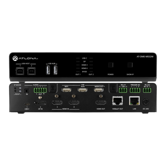
Panel Description Front Panel AT-OME-MS52W USB-C USB HOST USB HUB HDMI 3 HDMI 4 BYOD OUT 1 OUT 2 POWER SHOW IP IP MODE AUDIO RELAY TRIGGER I/O RS-232 WiFi MIRACAST RX TX USB HOST POWER RESET Connect a USB cable from each of these ports to Press this button to power-on or power off the AT- host computers. -
Page 11: Rear Panel
AT-OME-MS52W USB-C USB HOST USB HUB HDMI 3 HDMI 4 Panel Description BYOD OUT 1 OUT 2 POWER SHOW IP Rear Panel IP MODE AUDIO RELAY TRIGGER I/O RS-232 WiFi MIRACAST RX TX RESET INPUT OUTPUT DC 24V IP MODE OUTPUT (HDMI) Press and release this button to set the IP mode of Connect an HDMI cable from this port to an HD/UHD... -
Page 12: Installation
Installation Connectors RS-232 The AT-OME-MS52W provides an RS-232 port which can be used to control a display connected to the HDMI output. Atlona recommends controlling the AT-OME-MS52W using IP and reserving the RS-232 port for local display control. 1. Use wire strippers to remove a portion of the cable jacket. 2. -
Page 13: Relay
Installation Relay The AT-OME-MS52W provides a RELAY port, allowing the control of screens, curtains, and other devices. Use a 48 V DC relay with no more than 1 A current draw. When the AT-OME-MS52W is powered-on or rebooted, C1 and C2 are set to the Normally Open (NO) state. Trigger I/O The TRIGGER I/O port allows voltage-controlled devices, such as an occupancy sensor, to be connected to the AT-OME-MS52W. -
Page 14: Connection Instructions
Installation Connection Instructions 1. Connect up to two USB host computers to the USB HOST ports on the front panel. 2. Connect two USB devices, such as a speakerphone, to the USB HUB ports on the front panel. AT-OME-MS52W USB-C USB HOST USB HUB HDMI 3... - Page 15 Installation 9. Connect the included USB wireless antennas to the WiFi and MIRACAST™ ports. The WiFi port supports Google Cast™ and Apple AirPlay®. The MIRACAST™ only supports Miracast. IMPORTANT: Only use Atlona WiFi USB modules. Other WiFi modules may not be supported by this product.
-
Page 16: Connection Diagram
Installation Connection Diagram AT-OME-MS52W USB Wireless Antennas (included) S5 2W E- M -O M B HU ST 2 B HO Tablet (BYOD) AT-OME-EX-RX Laptop Laptop Laptop AT-HDVS-CAM Interactive Display AT-OME-MS52W... -
Page 17: Ip Configuration
Installation IP Configuration The AT-OME-MS52W is shipped with DHCP enabled. Once connected to a network, the DHCP server (if available), will automatically assign an IP address to the unit. Pressing the SHOW IP button will display the current IP address of the AT-OME-MS52W. -
Page 18: Switching The Ip Mode
Installation Switching the IP Mode AT-OME-MS52W If a static IP address is desired, the unit can be switched to static IP mode. Use one of the following procedures to USB-C switch between DHCP and static IP mode. The default static IP address of the AT-OME-MS52W is 192.168.1.254. USB HOST USB HUB HDMI 3... -
Page 19: Setting The Ip Address Using The Web Server
Installation Setting the IP Address using the Web Server The IP mode of the AT-OME-MS52W can also be set using the built-in web server. In order to access the web server, the IP address of the AT-OME-MS52W must be known. Refer to Logging in to the Web Server (page 22) for more information. -
Page 20: Resetting To Factory-Default Settings
AT-OME-MS52W USB-C Installation USB HOST USB HUB HDMI 3 HDMI 4 Resetting to Factory-Default Settings BYOD OUT 1 OUT 2 POWER SHOW IP 1. Press and hold the RESET button for five seconds. 2. Release the RESET button once the RESET LED indicator begins to flash. The LED indicator will flash three times to indicate that the unit has been reset to factory-default settings. -
Page 21: Device Operation
Device Operation LED Indicators The LED indicators on both the front and rear of the unit provide basic information on the current status of the AT-OME-MS52W. The POWER button has a backlit LED indicator. Description POWER Solid blue • Unit is powered and is in normal operating mode. Solid red •... -
Page 22: Logging In To The Web Server
Device Operation Logging in to the Web Server Most of the AT-OME-MS52W operation is handled through the built-in web server. In order to access the web server, the IP address of the unit must be known. Refer to IP Configuration (page 17) for more information. -
Page 23: Logging In After Registration
Device Operation Logging in after registration 1. Launch the desired web browser and enter the IP address of the AT-OME-MS52W in the address bar. 2. Enter the correct username and password in the respective fields. 3. Click the Login button. NOTE: If using a secure connection, click the Secure Login button. -
Page 24: Setting The System Date And Time
Device Operation Setting the System Date and Time The AT-OME-MS52W uses the internal clock to store the current date and time. When setting the time and date, Universal Coordinated Time (UTC) must be used. IMPORTANT: In order for proper unit operation, it is critical that the AT-OME-MS52W be set to the correct UTC time setting. -
Page 25: Setting Local Date And Time
Device Operation Setting Local Date and Time IMPORTANT: If the Local Date / Time field appears highlighted in (shown above), then this task must be performed to ensure proper functionality of the AT-OME-MS52W. 1. Login to the web server. Refer to Logging in to the Web Server (page 22) for more information. -
Page 26: Selecting The Input
Device Operation Selecting the Input 1. Login to the web server. Refer to Logging in to the Web Server (page 22) for more information. 2. Click Routing in the side menu bar. 3. Under the Input Selection window group, click the desired input. AT-OME-MS52W USB-C USB HOST... -
Page 27: Switching Modes
Device Operation Switching Modes The AT-OME-MS52W features two switching modes: Matrix Mode and Matrix Mode with static route. Each of these modes will be covered in the following section and are configured using the built-in web server. Matrix Mode This mode allows the AT-OME-MS52W to independently switch between any input to any output. Auto switching and display control is disabled in Matrix Mode. - Page 28 Device Operation 5. Click the Matrix Mode HDMI Source drop-down list and select the input to be routed to the HDMI OUT port. 6. Click the Matrix Mode HDBaseT Source drop-down list and select the input to be routed to the HDBaseT OUT port.
-
Page 29: Matrix Mode W/ Static Route
Device Operation Matrix Mode w/ Static Route This mode is desirable when integrating the AT-OME-MS52W with a video conference system and allows for auto switching and display control. In this mode, both static input and output routing are specified. Auto-Switching (page 31) must be enabled. - Page 30 Device Operation 5. Click the Matrix Mode Static Output drop-down list and select the output that will be “static”. This is the output that will not change. 6. Click the Matrix Mode Static Source drop-down to select the source that will be assigned as a “static” source. This source will be routed to the output selected in the Matrix Mode Static Output drop-down list.
-
Page 31: Auto-Switching
Device Operation Auto-Switching The AT-OME-MS52W provides auto-switching capability, which is enabled by default. This feature will automatically switch the input to the most recently-connected source. If a source is disconnected, then the input will automatically be switched to the previously-connected source. IMPORTANT: The auto-switching feature is only available when the Switching Mode is set to Matrix mode with static route or Disabled. -
Page 32: Usb Modes
USB-C Device Operation USB HOST USB HUB HDMI 3 HDMI 4 BYOD USB Modes OUT 1 OUT 2 The AT-OME-MS52W provides three USB modes: Manual, Follow USB, and Follow Video. Each mode provides different method of selecting the USB host ports. Note that the USB-C port also serves as a host port. USB HOST ports IP MODE AUDIO... -
Page 33: Auto Switch
Device Operation 5. Click the USB Host drop-down list and select the desired USB port. USB Host Description Host 1 USB HOST 1 port Host 2 USB HOST 2 port Remote Host Uses the USB host port on the HDBaseT receiver USB-C USB-C port 6. -
Page 34: Follow Video Input
Device Operation Once set to Auto Switch mode, the AT-OME-MS52W will exhibit the following behavior: • If only one USB host device is connected to the USB host ports, then the AT-OME-MS52W will use the USB host device connected to that port. •... - Page 35 Device Operation 6. Click the drop-down list, next to the desired input, to assign the USB host port to the input. In the example below, the HDMI3 (INPUT 3) is being assigned to Host 1 (USB HOST 1). 7. Configure other inputs as required. 8.
-
Page 36: The Splash Screen
Device Operation The Splash Screen The splash screen is displayed after the AT-OME-MS52W has completed the boot-up process, and indicates that the unit is ready for use. To view the splash screen, connect an HDMI cable to OUTPUT 1 (HDMI) or OUTPUT 2 (HDBaseT) on the AT-OME-MS52W to the HDMI input of a display. - Page 37 Device Operation Title Welcome Column Title MS52W-B500 To begin your presentation: Subtitle Connect wired: Connect wirelessly: Connect the HDMI, USB-C, Search for MS52W-B500 or DisplayPort cable on your AirPlay, at the table to your GoogleCast (Google Home App), device. or Miracast device. Column #1 Help Videos - http://atlona.com/casting Column #2...
- Page 38 Device Operation 5. Click the Legend link to display a list of these tags at any time. 6. The Y Offset field is used to adjust the horizontal centering of the panel. The default value is 0 (center). Positive values will shift the panel to the right. Negative values will shift the panel to the left. Adjusting the Y Offset does not move the background image of the splash screen.
-
Page 39: Displaying Metadata
Device Operation Displaying Metadata Click the Meta Data checkbox to display metadata information on the splash screen. Metadata includes the name of the unit, model, current date, wired IP address, current firmware version, and some image references used by the AT-OME-MS52W. -
Page 40: Displaying The Wireless Password
Device Operation Displaying the Wireless Password This feature is applicable only when the AT-OME-MS52W is configured as an access point. The wireless password can be displayed as part of any text field on the splash screen, by inserting the {password} tag as part of a text string. -
Page 41: Cycling Background Images
Device Operation Cycling Background Images Background image cycling can prevent image persistence, which is the equivalent of image burn-in on CRT and plasma computer monitors. 1. Login to the web server. Refer to Logging in to the Web Server (page 22) for more information. -
Page 42: Uploading Custom Images
Device Operation Uploading Custom Images Custom images may be uploaded and used instead of the factory splash screens. IMPORTANT: Custom images should not exceed 1920 x 1080. All common image types, such as JPG, BMP, PNG, TIF, GIF, are supported. 1. -
Page 43: Html Splash Screens
Device Operation HTML Splash Screens HTML-based splash screens can be used to create content-rich splash screens. This section provides details on creating and uploading an HTML splash screen. Familiarity with HTML is assumed. The AT-OME-MS52W comes with a default HTML splash screen, which can be downloaded from within the web server. The following table provides a list of supported / unsupported features: Feature Supported... - Page 44 Device Operation Using a custom HTML file 1. Create the HTML file, along with any links to the desired images. The AT-OME-MS52W also comes with a default HTML file (refer to the previous page), and can be used as a starting point when creating a custom HTML splash screen.
- Page 45 Device Operation The file structure for the default html.zip file, located on the AT-OME-MS52W, is as follows: airplay.png cast.png chrome.png devices.png index.html_template wifi.png windows.png 4. Login to the web server. Refer to Logging in to the Web Server (page 22) for more information.
-
Page 46: Resetting The Html Splash Screen
Device Operation Resetting the HTML Splash Screen IMPORTANT: The Reset (Reset HTML) button will delete any loaded HTML data and replace it with the default HTML page that comes with the AT-OME-MS52W. 1. Login to the web server. Refer to Logging in to the Web Server (page 22) for more information. -
Page 47: Wireless Configuration
Device Operation Wireless Configuration The AT-OME-MS52W features a wireless gateway, providing convenient Wi-Fi connectivity to iOS, Android, Mac, ® Chromebook, or Windows-based devices. In addition, the AT-OME-MS52W can be configured as a wireless access point (AP). The addition of a built-in firewall provides filtering of outbound traffic from WAP to Ethernet. Access Point Mode When configured as an Access Point (AP), wireless devices can be connected to the AT-OME-MS52W. - Page 48 Device Operation 6. The Show AP Credentials checkbox is enabled by default. Enabling this feature will display the WiFi Name and WiFi Password fields to be displayed on the splash screen, as shown below. Uncheck this box to hide the name and password.
- Page 49 Device Operation 11. Enter the wireless channel number in the Channel field. Channels 1 through 11 are 2.5 GHz channels. Channels 36 and above are 5 GHz channels. Contact the network administrator if necessary. 12. Click the Access Point Power Level drop-down list to select the desired power level of the WiFi USB antenna. Available values are integers 0 through 13.
-
Page 50: Firewall Mode
Device Operation Firewall Mode This feature allows filtering of outgoing network traffic, from/to a network that is connected to the LAN port on the AT-OME-MS52W. The AT-OME-MS52W provides the following firewall modes: Block Private Network, Block Internet, Block All, and None. If this feature is not desired, then the following steps can be skipped. The firewall can be configured or disabled at any time. -
Page 51: Connect To Wifi Mode
Device Operation Connect to WiFi Mode Use this mode to connect the AT-OME-MS52W to another wireless network. 1. Login to the web server. Refer to Logging in to the Web Server (page 22) for more information. 2. Click Administration > Networking in the side menu bar. 3. - Page 52 Device Operation 6. Click the desired WiFi network from the list and click the OK button to accept the selection or click Cancel to return to the WiFi window group. 7. Enter the password for the wireless network in the Password field. 8.
- Page 53 Device Operation 9. The system will prompt to be rebooted, as shown below. Click Yes to perform a reboot. To reboot at a later time, click the Later button. Once the connection has been established, the Status field will display Connected, as shown below. The following table provides a description of status messages.
-
Page 54: Changing The Ssid
Device Operation Changing the SSID By default, the SSID of the AT-OME-MS52W is set to the following identifier: ms52w-{id}. The first five digits are the last five characters of the product SKU. The {id} tag holds the last four digits of the MAC address. This identifier is held in the Name field, under the General tab. -
Page 55: 802.1X Authentication
Device Operation 802.1X Authentication 802.1X is a server-based port authentication protocol which restricts unauthorized (rogue) clients from connecting to a Local Area Network through a public port. In its simplest form, 802.1X usually involves three parties: supplicant (client device), authenticator (Ethernet switch), and an authentication server. Before the device is permitted on the network, port communication is restricted to Extensible Authentication Protocol over LAN (EAPOL) traffic. - Page 56 Device Operation 5. Enter the identity of the authentication server in the Identity field. EAP uses this field to identify the correct authentication server which will process the credentials. For example, if foo@authserv.com is entered, then this identifies AUTHSERV as the RADIUS (authentication) server. 6.
-
Page 57: Wifi Connections
Device Operation WiFi Connections 1. Login to the web server. Refer to Logging in to the Web Server (page 22) for more information. 2. Click Administration > Networking in the side menu bar. 3. Under the WiFi window group, click the 802.1x Security Enable check box. 4. -
Page 58: Casting
Device Operation Casting The AT-OME-MS52W interface provides the ability to transmit (“cast”) the screen of any iOS , Android , macOS ® ™ ® Chromebook, or Windows device over Wi-Fi, without having to install a separate application or driver. The AT-OME- MS52W can serve as an integrated, dual-band access point, or be networked into an existing Wi-Fi installation. -
Page 59: Os X Devices
Device Operation 6. Tap the SSID from the list of devices. 7. Close the Control Center by either swiping down or pressing the Home button. 8. The image of the iOS device will now appear on the connected display. Note that depending upon the application, the image on the screen can be rotated. - Page 60 Device Operation AirPlay can be used to either mirror or extend the Mac display. • Mirroring Click the AirPlay icon in the menu bar and select the desired display to be mirrored. • Extending Click the AirPlay icon and select “Use As Separate Display” from the list of displays, to extend the Desktop to another display.
-
Page 61: Microsoft Miracast
Device Operation Microsoft Miracast Miracast is a wireless protocol that allows content to be transmitted from laptops and other mobile devices to displays. The latest release of Microsoft Windows 10 supports Miracast. ® Displaying Miracast devices can be done in more than one way. Three methods are discussed below. The first method is the most direct method. - Page 62 Device Operation Chrome will immediately begin casting to the AT-OME-MS52W. 6. Adjust the volume (if audio is present), by clicking and dragging the slider control. In addition, either Remote screen or Both screens can be selected from the Show fullscreen videos on drop-down list. 7.
-
Page 63: Audio Management
Device Operation AT-OME-MS52W USB-C Audio Management USB HOST USB HUB HDMI 3 HDMI 4 By default, the AT-OME-MS52W will use the digital audio (if present) from the USB-C IN, DisplayPort, or HDMI ports BYOD and output the audio over the HDMI OUT, HDBaseT OUT, and AUDIO OUT ports. However, an external analog OUT 1 OUT 2 POWER... -
Page 64: Airplay Bluetooth Discovery
Device Operation AirPlay Bluetooth Discovery The AT-OME-MS52W supports Bluetooth®-assisted device discovery. An optional Bluetooth adapter is required, but not included. Atlona recommends Plugable and Kinivo Bluetooth 4.0 adapters. IMPORTANT: Bluetooth discovery is applicable only to Apple devices and is used for device discovery on networks, such as corporate networks, where mDNS is not permitted. -
Page 65: Airplay / Miracast P2P Pin Codes
Device Operation AirPlay / Miracast P2P PIN Codes The AT-OME-MS52W can be configured to prompt for a PIN code, before a BYOD device connects with either AirPlay or Miracast P2P. When the this option is enabled, a PIN code will be displayed on the screen when an AirPlay or Miracast device attempts to connect to the AT-OME-MS52W. - Page 66 Device Operation 5. Connect the AirPlay/Miracast P2P device to the AT-OME-MS52W. Refer to Wireless Configuration (page 47) for more information. 6. Begin casting to the AT-OME-MS52W. When the device attempts to connect to the AT-OME-MS52W, a PIN code will be displayed on the screen that is connected to the device. Refer to the illustration on the next page, if necessary.
-
Page 67: Changing The Pin Timeout
Device Operation Changing the PIN Timeout By default, the AT-OME-MS52W will automatically generate a new PIN code for each new WiFi connection that is attempted. However, this value can also be set to regenerate every 15 minutes or 60 minutes. NOTE: The AT-OME-MS52W requires a minimum of 20 seconds to elapse before another PIN code is generated. -
Page 68: Moderator Mode
Device Operation Moderator Mode Moderator mode provides a layer of control when multiple clients are casting through the AT-OME-MS52W. The “moderator” can either allow or kick (remove) a client from casting content. Up to four users can be hosted in the Users table. - Page 69 Device Operation 6. Click the Allow button to permit a device to begin casting to the display device. Once the selected device is allowed to cast to the connected display device, the Allow button will be disabled. In the example below, Brenda’s iPhone is now the active casting device and shown on the display device. 7.
- Page 70 Device Operation 8. Click the Kick button to explicitly disconnect a casting device from the AT-OME-MS52W. Any casting device can be “kicked”, even if it is the active casting device. Active casting device Once a device has been “kicked”, it will no longer appear in the Users table. In the example below, the device Andrew’s iPhone has been removed from the Users table.
-
Page 71: Display Control Methods
Device Operation Display Control Methods The AT-OME-MS52W provides various methods for display control. The following section describes and provides instructions for each method. By default, the AT-OME-MS52W uses CEC commands to control the display. Active Video Presence This method will instruct the AT-OME-MS52W to toggle power on the display, based on the absence/presence of either a video signal on any of the physical inputs or a casting device. - Page 72 Device Operation 5. Click the Auto Power Off Timer drop-down list and select the desired time interval. This is the amount of time that must elapse, before the display is turned off. 6. Setup is complete. AT-OME-MS52W...
-
Page 73: Active Video Presence With Occupancy Sensor
Device Operation Active Video Presence with Occupancy Sensor This method is similar to the Active Video Presence mode, except that an occupancy sensor can also be used to provide hybrid operation. If using this mode, an occupancy sensor should be connected to the TRIGGER I/O port on the AT-OME-MS52W. -
Page 74: Occupancy Sensor
Device Operation Occupancy Sensor This method uses an occupancy sensor to control the display. AutoSwitch does not need to be enabled for this feature to work. 1. Login to the web server. Refer to Logging in to the Web Server (page 22) for more information. -
Page 75: Day And Time
Device Operation Day and Time This method allows manual setup of day and time to determine when the display device will be power-on and powered-off. AutoSwitch does not need to be enabled for this feature to work. 1. Login to the web server. Refer to Logging in to the Web Server (page 22) for more information. -
Page 76: Access Point
Device Operation Access Point This method uses the presence or aobsence of a wireless connection to determine the power state of the system. In order for this feature to work, the AT-OME-MS52W must be set as an Access Point. Refer to Access Point Mode (page 47) for more information. -
Page 77: Changing The Password
Device Operation Changing the Password 1. Login to the web server. Refer to Logging in to the Web Server (page 22) for more information. 2. Click Administration > User Accounts in the side menu bar. 3. Under the User Accounts window group, click the Change button. 4. -
Page 78: Configuration And Management Interfaces
Configuration and Management Interfaces Web Server The AT-OME-MS52W includes a built-in web server. Atlona recommends that the web server be used to set up the AT-OME-MS52W, as it provides intuitive management of all features. Refer to Logging in to the Web Server (page for more information. -
Page 79: Login Page
Configuration and Management Interfaces Login page This page is displayed when the IP address of the AT-OME-MS52W is entered in the address bar of a web browser. User Enter the username in this field. The username is admin. Password Enter the password in this field. The default password is Atlona. It is recommended that the password be changed. Refer to Changing the Password (page 77) for more information. -
Page 80: Info Page
Configuration and Management Interfaces Info page After logging in, the Info page will be displayed. The Info page provides basic information about the receiver, including the model name, software version, input video timing, and the device being using as the transmitter. Info Model Name The model SKU of this product. -
Page 81: General Page
Configuration and Management Interfaces General page General Name This is the hostname of the unit. Enter the desired name of the AT-OME-MS52W in this text field. Include the {id} tag to use the last four digits of the hardware MAC address. Hostnames can contain alphabetic and numeric characters. NOTE: The hardware MAC address differs from the MAC address of the unit, which is found on an adhesive label applied to the the bottom of the unit. -
Page 82: System Page
Configuration and Management Interfaces System page System Display name This field serves as the SSID, when connecting wirelessly to the AT-OME-MS52W. This name can be changed in the Name field of the General tab. Refer to General page (page 81) for more information. - Page 83 Configuration and Management Interfaces Firmware Model Name The SKU of the product: AT-OME-MS52W. Master Version The master version of firmware. Always make sure to check the AT-OME-MS52W product page, on the Atlona web site, for the latest version of firmware. Download Click this link to download the latest firmware.
- Page 84 Configuration and Management Interfaces Configuration Download Click this button to download the current AT-OME-MS52W configuration to a .zip file. The default filename is config.zip. Within the config.zip is the configuration.zip file. Note that the information within the configuration.zip file cannot be extracted as it is only readable by the AT-OME-MS52W. Upload Click this button to upload the configuration file to the AT-OME-MS52W.
-
Page 85: Status Page
Configuration and Management Interfaces Status page Status This page provides a information about the current state of the AT-OME-MS52W, such as IP information, memory usage, casting devices, active sources, date/time, and various other settings. AT-OME-MS52W... -
Page 86: Splash Screen Page
Configuration and Management Interfaces Splash Screen page This page provides control over the appearance of the splash screen. Refer to The Splash Screen (page 36) more information on using each of the settings under the Splash Screen and Images window groups. Splash Screen Type Click this drop-down list to select... - Page 87 Configuration and Management Interfaces Column Title The title text for the centered text, above both instruction columns. The default text is “To begin your presentation”. Column #1 The text positioned in the left column. The default text is “Connect wired: Connect the HDMI, USB-C, or DisplayPort cable at the table to your device”.
- Page 88 Configuration and Management Interfaces Images Upload Click these buttons to replace each factory-default image with a custom image. Reset Splash Images Click the Reset button to set the splash screen images to the factory-default images. Enable Image Rotation Click this check box to instruct the AT-OME-MS52W to cycle through the splash screen images.
-
Page 89: Routing Page
Configuration and Management Interfaces Routing page This page provides control over the appearance of the splash screen. Refer to The Splash Screen (page 36) more information on using each of the settings under the Splash Screen and Images window groups. Input Selection USBC, DP, HDMI3, HDMI4, BYOD Click the desired button to select the active input. -
Page 90: Usb Routing Page
Configuration and Management Interfaces USB Routing page USB Routing Refer to USB Modes (page 32) for more information. USB Routing Mode Click this drop-down list to select the USB routing mode. Modes Description Manual This is the default mode and provides manual selection of the USB host port to be used, when switching video inputs. -
Page 91: Display Page
Configuration and Management Interfaces Display page Control AutoSwitch Click this box to enable or disable auto-switching. When this box is checked, the AT-OME-MS52W will automatically switch inputs when the new device is connected. To disable auto-switching, uncheck this box. Display Control Method Click this drop-down list to select the method of display control. - Page 92 Configuration and Management Interfaces Lamp cool down timer Sets the projector lamp cool-down timer, in seconds. This value specifies the time interval that must elapse, after the display control “off” command is sent, before the display “power on” command can be sent. This feature is used to prevent the projector from missing a “power on”...
- Page 93 Configuration and Management Interfaces CEC Commands Click these button to test CEC functionality over HDMI and HDBaseT. Click the On button to send the power-on command to the display device. Click the Off button to send the power-off command to the display device. Relay Enable Momentary Relay When enabled, the relay is set to momentary.
- Page 94 Configuration and Management Interfaces RS-232 This section is only available when the Control Type is set to RS-232. RS-232 Mode Click this drop-down list to select the RS-232 mode. Setting Description HDBaseT RS232 Only Assigns settings for RS-232 settings over HDBaseT OUT. RS-232 commands will only be transmitted over the HDBaseT OUT port.
- Page 95 Configuration and Management Interfaces This section is only available when the Control Type is set to IP. IP address Enter the IP address of the display device in this field. Port Enter the port number in this field. RS-232/IP Commands This section is only available when the Control Type is set to either RS-232 or IP.
- Page 96 Configuration and Management Interfaces Products Click this drop-down list to select the product. This drop-down list will be populated, based on the selection made from the Manufacturer drop-down list. Model Click this drop-down list to select the model. This drop-down list will be populated based on the selection made in the Products drop-down list.
-
Page 97: Edid Page
Configuration and Management Interfaces EDID page EDID EDID (Extended Display Identification Data) Displays the EDID assigned that is being used by each output. Press the Save button to save the EDID to a file. Inputs The Input column displays each of the inputs on the AT-OME-MS52W. Click the drop-down list, under the Selection column, to select the desired EDID to be used. -
Page 98: Administration > Telnet Page
Configuration and Management Interfaces Administration > Telnet page The Telnet page provides an emulated terminal for entering commands. AT-OME-MS52W... -
Page 99: Administration > Moderator Page
Configuration and Management Interfaces Administration > Moderator page The Moderator page provides control of which device, that are casting, are permitted to display content. Refer to Moderator Mode (page 68) for more information. Moderator Enable Click this check box to enable or disable Moderator mode. If this box is checked, then Moderator mode is enabled. In order to monitor which devices are allowed to display content, this box must be checked before a device begins casting. -
Page 100: Administration > Networking Page
Configuration and Management Interfaces Administration > Networking page This page contains a WiFi and Ethernet tab. Use the settings, under these tabs, to connect the AT-OME-MS52W to a network or wireless Access Point (AP). Refer to the IT Network Deployment Guide for detailed information on configuring the AT-OME-MS52W in various network environments. - Page 101 Configuration and Management Interfaces IP Address Enter the desired IP address for the AT-OME-MS52W in this field. This field can only be changed when Mode is set to Static. Network Mask Enter the subnet mask in this field. This field can only be changed when Mode is set to Static. Gateway Enter the gateway (router) address in this field.
- Page 102 Configuration and Management Interfaces WiFi - Access Point Mode Mode Click this drop-down list to select the desired WiFi mode. Setting Description Access Point Select this option to configure the AT-OME-MS52W as a Wireless Access Point, allowing other wireless devices to connect to the same wired network as the AT- OME-MS52W.
- Page 103 Configuration and Management Interfaces Rotate Password Click this check box to randomly generate a new password after the specified time interval has expired. Channel Click this drop-down list to select the desired wireless channel. Channels 1 through 11 are 2.5 GHz channels. Channels 36 and above are 5 GHz channels.
- Page 104 Configuration and Management Interfaces WiFi - Connect to WiFi Mode Mode Click this drop-down list to select the desired WiFi mode. Setting Description Access Point Select this option to configure the AT-OME-MS52W as a Wireless Access Point, allowing other wireless devices to connect to the same wired network as the AT- OME-MS52W.
- Page 105 Configuration and Management Interfaces IP Address The IP address of the wireless network which the AT-OME- MS52W is connected. Network Mask The network mask of the wireless network which the AT-OME- MS52W is connected. Gateway This field cannot be changed. DNS Server #1 / DNS Server #2 These fields cannot be changed.
-
Page 106: Administration > Debug Page
Configuration and Management Interfaces Administration > Debug page Click the Download Logs button to download the debug logs. Debug logs are downloaded in a .zip file. Debug logs are used by Atlona Technical Support Engineers to identify functionality issues. 1. Click Debug on the side menu bar. 2. -
Page 107: Administration > User Accounts Page
Configuration and Management Interfaces Administration > User Accounts page This page allows the default password to be changed. 1. Click the Change button to display the Change Password dialog box. 2. Enter the new password in the Password field. 3. Re-enter the same password in the Repeat Password field. 4. -
Page 108: Administration > Advanced Page
Configuration and Management Interfaces Administration > Advanced page This page provides options for advanced functionality. Telnet Enable Telnet Click this check box to enable or disable the Telnet protocol for the AT-OME-MS52W. When checked, Telnet is enabled. Telnet Authentication Click this check box to enable or disable the Telnet authentication. When checked, Telnet is enabled. When this feature is enabled, username and password credentials will be required at the beginning of the Telnet session. - Page 109 Configuration and Management Interfaces BYOD Max BYOD Time Click this drop-down list to select the desired time interval before the connected BYOD is automatically disconnected from the AT-OME-MS52W. Available options are 35 minutes to 5 hours. Kick User Click this button to disconnect the current BYOD. Airplay Bluetooth - Ethernet Click this check box to enable Bluetooth discovery when using an Ethernet connection.
- Page 110 Configuration and Management Interfaces Airplay Enable Click this check box to enable AirPlay. This option is enabled by default. Google Cast Enable Click this check box to enable Google Cast . This option is enabled by default. ™ Miracast Enable Click this check box to enable Miracast.
- Page 111 Configuration and Management Interfaces Enable REST API Authentication Enables or disables REST authentication when using the AT-OME-MS52W API. Click this check box to enable the feature. Enable CORS Check this box to enable Cross-Origin Resource Sharing (CORS). This allows the AT-OME-MS52W to connect with certain servers.
-
Page 112: Administration > Pre-Release Page
Configuration and Management Interfaces Administration > Pre-Release page This page lists beta features, which are currently in the pre-release / testing stage. It should be noted that these features may not function reliably. Pre-Release Features listed under this window group can change between versions. As these features are not officially released, they are not documented. -
Page 113: Administration > Audio Page
Configuration and Management Interfaces Administration > Audio page This page provides control over the audio output level, as well as selecting analog or digital audio sources for each input. Audio Master Volume Click and drag this slider to adjust the output volume. Output is adjustable from -80 to 0 dB. Audio Input HDMI 3, HDMI 4, USB-C, DP Click these drop-down lists to select the desired audio input source. -
Page 114: Administration > Event Viewer Page
Configuration and Management Interfaces Administration > Event Viewer page This page displays a dynamic list of events, returned in JSON format. The image below, shows a list of sample events. This page is useful for monitoring events and troubleshooting the AT-OME-MS52W. AT-OME-MS52W... -
Page 115: Appendix
Appendix Updating the Firmware Updating the firmware is performed using the built-in web server. Requirements: • AT-OME-MS52W • Firmware files • Computer on the same network as the AT-OME-MS52W 1. Download the firmware from atlona.com and extract the contents of the .zip file to a folder on the computer desktop. - Page 116 Appendix 8. After the firmware process has completed, the AT-OME-MS52W will automatically reboot and the following message will appear at the top of the screen. 9. Click the message or press the ESC key to return to the Login screen. Enter the login credentials. 10.
-
Page 117: Mounting Instructions
Appendix Mounting Instructions The AT-OME-MS52W can be mounted in different ways, based on the number of units that are being installed. The AT-OME-MS52W can be mounted in a rack or on/under any flat surface. NOTE: Rack ears (Altona part no. AT-UHD-SW-510W-RM) are sold separately. Contact Atlona for more information. -
Page 118: Dual-Unit Rack Installation
Appendix Dual-unit Rack Installation 1. Turn both units upside-down on a flat surface, next to each other, as shown. 2. Position the included mounting plates over the holes on the bottom of the enclosure. When attaching mounting plates, the countersink bevels on the mounting plate should face upward. Countersink bevel 3. -
Page 119: Flat Surface
Appendix Flat Surface 1. Turn the unit upside down, on a flat surface. 2. Position the included mounting plates over the pre-drilled holes on the bottom of the enclosure. When attaching mounting plates, the countersink bevels on the mounting plates should face upward. Countersink bevel 3. -
Page 120: Specifications
Appendix Specifications Video HDMI HDCP 2.2 (wired-device connections, only) UHD/HD 4096×2160 @ 60 /50/30/25/24 Hz 720x576p @ 50 Hz 3840×2160 @ 60 /50/30/25/24 Hz 720x576i @ 50 Hz 1920x1080p @ 60/59.9/50/30/29.97/25/24/23.98 Hz 640x480p @ 60/59.96 Hz 1920x1080i @ 30/29.97/25 Hz 640x480i @ 30 Hz 1280x720p @ 60/59.94/50 Hz 2560×1600... - Page 121 Appendix Control RS-232 Device control and configuration Bidirectional pass-through from control system over HDBaseT Supported baud rates: 2400, 4800, 9600, 19200, 38400, 57600, 115200 Protocols: HTTPS, Telnet, mDNS Modes: DHCP, Static – selectable through front panel and built-in web server Resolution / Distance 4K/UHD - Feet / Meters 1080p - Feet / Meters...
- Page 122 Appendix Dimensions (H xW x D) Inches Millimeters Device 1.65 x 8.62 x 10 42 x 219 x 254 Power Supply (AT-PS-245-D4) 1.6 x 2.6 x 6.2 40.6 x 66 x 157.4 Weight Pounds Kilograms Device 3.89 1.77 Certification Device CE, FCC Power CE, FCC, UL...
- Page 123 Toll free US International atlona.com 877.536.3976 41.43.508.4321 • • © 2020 Atlona Inc. All rights reserved. “Atlona” and the Atlona logo are registered trademarks of Atlona Inc. All other brand names and trademarks or registered trademarks are the property of their respective owners. Pricing, specifications and availability subject to change without notice.
Need help?
Do you have a question about the Atlona OMEGA AT-OME-MS52W and is the answer not in the manual?
Questions and answers