
Subscribe to Our Youtube Channel
Related Manuals for Panduit Atlona AT-UHD-CLSO-840


Summary of Contents for Panduit Atlona AT-UHD-CLSO-840
- Page 1 4K/UHD 8x4 HDBaseT and HDMI Matrix Switcher with PoE Atlona Manuals AT-UHD-CLSO-840 Switchers...
- Page 2 Version Information Version Release Date Notes 09/18 New format AT-UHD-CLSO-840...
- Page 3 Welcome to Atlona! Thank you for purchasing this Atlona product. We hope you enjoy it and will take a extra few moments to register your new purchase. Registration only takes a few minutes and protects this product against theft or loss. In addition, you will receive notifications of product updates and firmware.
- Page 4 Atlona, Inc. (“Atlona”) Limited Product Warranty Coverage Atlona warrants its products will substantially perform to their published specifications and will be free from defects in materials and workmanship under normal use, conditions and service. Under its Limited Product Warranty, Atlona, at its sole discretion, will either: •...
- Page 5 Atlona, Inc. (“Atlona”) Limited Product Warranty • Damage, deterioration or malfunction resulting from the installation or removal of this product from any installation, any unauthorized tampering with this product, any repairs attempted by anyone unauthorized by Atlona to make such repairs, or any other cause which does not relate directly to a defect in materials and/or workmanship of this product.
- Page 6 Important Safety Information 9. Do not defeat the safety purpose of a polarized CAUTION or grounding-type plug. A polarized plug has two RISK OF ELECTRIC SHOCK blades with one wider than the other. A grounding DO NOT OPEN type plug has two blades and a third grounding CAUTION: TO REDUCT THE RISK OF prong.
-
Page 7: Table Of Contents
Table of Contents Introduction Features Package Contents Panel Description Front Rear Installation Audio Connectors Connection Instructions Setting the IP Mode Connection Diagram Basic Operation Powering the Matrix Standby Mode Viewing Matrix Settings Viewing the current routing state Displaying the System Settings Routing Inputs to Outputs Single Input-to-Output Routing Routing a Single Input to All Outputs... - Page 8 Table of Contents The Web GUI Introduction to the Web GUI Menu Bar Status page System Information Load system settings Firmware page Matrix HDBaseT Remote Firmware Update Network page Control page Users page I/O page Input/Output Selection Input Label Output Label Route Memory page Route Memory Memory Label...
-
Page 9: Introduction
Introduction The Atlona AT-UHD-CLSO-840 is a 4K/UHD 8×4 matrix switcher for HDMI and HDBaseT with eight inputs, four discrete outputs, audio integration capabilities, and Ethernet-enabled 100 meter HDBaseT extension with PoE remote device powering. It is ideal for presentation environments with content on multiple displays, as well as videoconferencing, presentation capture, and divisible rooms. -
Page 10: Panel Description
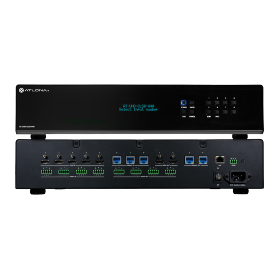
Panel Description Front POWER ENTER CANCEL EDID INFO AT-UHD-CLSO-840 RX TX HDMI IN HDBaseT IN HDMI OUT HDBaseT OUT RS-232 Front Panel Display This 16-character, two-row display provides the status of the matrix during various operations. AUDIO IN AUDIO OUT POWER PWR 100-240VAC 50/60Hz... -
Page 11: Rear
Panel Description POWER ENTER Rear CANCEL EDID INFO AT-UHD-CLSO-840 RX TX RS-232 HDMI IN HDBaseT IN HDMI OUT HDBaseT OUT AUDIO IN AUDIO OUT PWR 100-240VAC 50/60Hz HDMI IN Connect up to five 4K UHD source devices to these ports using HDMI cables. AUDIO IN Connect up to four analog audio sources to these ports using the included 5-pin captive screw blocks. -
Page 12: Installation
Installation Audio Connectors The AUDIO IN and AUDIO OUT ports on the AT-UHD-CLSO-840 provide analog inputs and outputs, respectively, for audio. Use the included 5-pin captive screw blocks to connect either balanced or unbalanced analog sources/ outputs. Balanced XLR Wiring Rear View Rear View Unbalanced RCA Wiring... -
Page 13: Connection Instructions
Installation Connection Instructions 1. Connect up to five HD/UHD sources to the HDMI IN (1 - 5) ports. 2. Connect up to three PoE-compatible transmitters (e.g. AT-HDVS-210H-TX-WP) to the HDBaseT IN (6 - 8) ports using Ethernet cables. 3. Connect up to two UHD/HD displays to the HDMI OUT (1 - 2) ports using HDMI cables. 4. -
Page 14: Setting The Ip Mode
Installation Setting the IP Mode The AT-UHD-CLSO-840 is shipped with DHCP enabled. Once connected to a network, the DHCP server (if available), will automatically assign an IP address to the unit. If no DHCP server is found or available, then the matrix will be set to the following IP settings: Default IP settings Description... - Page 15 Installation Using the web GUI 1. Login to the web GUI. Refer to Introduction to the Web GUI (page 55) for more information. 2. Click Network, under the Settings section in the menu bar on the left side of the screen. •...
-
Page 16: Connection Diagram
Installation Connection Diagram Atlona Velocity™ or third-party control system AT-UHD-CLSO-840 CT OR HD display RS -2 se T C 50 40 VA R 10 AT-UHD-EX-100CE-RX se T DI O DI O 5x HD sources P ro D en H ig HD display se T RS -23... -
Page 17: Basic Operation
Basic Operation Powering the Matrix The master power button is located on the rear panel of the matrix. This rocker switch allows power to be applied to POWER ENTER the matrix. CANCEL EDID INFO 1. Press the ON/OFF button so that it is in the ON position. To power-off the matrix, push the button to the OFF AT-UHD-CLSO-840 position. -
Page 18: Standby Mode
Basic Operation Standby Mode The POWER button on the front panel of the matrix, allows the matrix to be powered-on or placed in standby mode. 1. Locate the POWER button on the front panel. When the matrix is in normal operating mode, the POWER button will be backlit by a solid blue light. -
Page 19: Viewing Matrix Settings
Basic Operation Viewing Matrix Settings The front panel display provides the current status of the matrix and its settings. The buttons on the front panel can be used to display the current routing settings as well as network settings. Viewing the current routing state 1. -
Page 20: Displaying The System Settings
Basic Operation Displaying the System Settings 1. Make sure the home screen is displayed. If the home screen is not displayed, press the CANCEL button to return to the home screen. 2. Press and release the FNC button to display the SELECT FUNCTION screen. ... -
Page 21: Routing Inputs To Outputs
Basic Operation Routing Inputs to Outputs When the AT-UHD-CLSO-840 is shipped from the factory, the matrix is set to “one-to-one” routing mode. This means that input 1 is routed to output 1, input 2 is routed to output 2, and so on. The following section describes how to change the routing state. - Page 22 Basic Operation Using the web GUI As in the previous example, HDMI IN 3 will be routed to HDBaseT OUT 4. 1. Login to the web GUI. Refer to Introduction to the Web GUI (page 55) for more information. 2. Click I/O, under the Configuration section, in the menu bar on the left side of the screen. 3.
-
Page 23: Routing A Single Input To All Outputs
Basic Operation Routing a Single Input to All Outputs Using the Front Panel This procedure will route a single input to all eight outputs. 1. Make sure the home screen is displayed. If the home screen is not displayed, press the CANCEL button to return to the home screen. - Page 24 Basic Operation Using the web GUI As in the previous example, HDMI IN 2 will be routed to all outputs. 1. Login to the web GUI. Refer to Introduction to the Web GUI (page 55) for more information. 2. Click I/O, under the Configuration section, in the menu bar on the left side of the screen. 3.
-
Page 25: Audio Routing
Basic Operation Audio Routing The AT-UHD-CLSO-840 provides various options for embedding, de-embedding, and routing audio. Audio routing is managed through the web GUI or using API commands. The following section provides details on each option. IMPORTANT: Direct routing between AUDIO IN and AUDIO OUT ports is not supported, as shown ... - Page 26 Basic Operation Routing table for analog audio inputs to digital outputs. Input Output AUDIO IN 1 HDMI OUT 1 AUDIO IN 2 HDMI OUT 2 AUDIO IN 3 HDBaseT OUT 3 AUDIO IN 4 HDBaseT OUT 4 1. Login to the web GUI. Refer to Introduction to the Web GUI (page 55) for more information.
-
Page 27: Digital Inputs To Analog Audio Outputs
Basic Operation Digital Inputs to Analog Audio Outputs Audio can be de-embedded from the digital inputs (HDMI IN 1 - 5, HDBaseT 6 - 8) and routed to any one of the analog audio outputs (AUDIO OUT 1 - 4). Source audio is automatically down-mixed to two-channel audio. ... - Page 28 Basic Operation 5. Click the drop-down list, to the right of the Mirror drop-down list, and select In 2: Input 2. 6. Click the Save button to commit changes. Digital audio from HDMI IN 2 is now down-mixed to two-channel audio and output to AUDIO OUT 3.
-
Page 29: Analog Or Digital Audio To Digital Outputs
Basic Operation Analog or Digital Audio to Digital Outputs Audio from digital inputs (HDMI IN 1 - 5, HDBaseT 6 - 8) or analog inputs (AUDIO IN 1 - 4) can be routed to any of the digital outputs (HDMI IN 1 - 2, HDBaseT 3 - 4). In addition, any one of the analog audio inputs can be used ... - Page 30 Basic Operation 5. Click the drop-down list, directly to the right, and select In 7: Input_7. This will select the HDBaseT In 7 port. 6. Click the Save button to commit changes. The analog audio source on AUDIO IN 1 will now replace the digital audio on the HDBaseT IN 7 port, and the result will be output on HDBaseT OUT 3.
-
Page 31: Audio Mirroring
Basic Operation Audio Mirroring Audio mirroring can be enabled or disabled: • When enabled, the audio from the source that is being viewed, can be routed to a specified AUDIO OUT port. This allows the audio to be processed by a DSP or other audio output device. •... - Page 32 Basic Operation 1. Login to the web GUI. Refer to Introduction to the Web GUI (page 55) for more information. 2. Click I/O, under the Configuration section, in the menu bar on the left side of the screen. 3. Locate the desired output under the Audio out follows section. As shown in the diagram on the previous page, the audio from HDBaseT OUT 3 is mirrored to the AUDIO OUT 1 port.
-
Page 33: Disabling Audio Mirroring
Basic Operation Disabling Audio Mirroring When mirroring is disabled, the audio on an AUDIO OUT port can be selected from any of eight inputs. In the example below, audio mirroring has been disabled, allowing the audio from a different source (Source 2 connected to HDMI IN 5) to be routed to the DSP (AUDIO OUT 1). - Page 34 Basic Operation 1. Login to the web GUI. Refer to Introduction to the Web GUI (page 55) for more information. 2. Click I/O, under the Configuration section, in the menu bar on the left side of the screen. 3. Locate the desired output under the Audio out follows section. In this example, the audio from HDMI IN 5 is output on the AUDIO OUT 1 port.
-
Page 35: Creating And Editing Routing Presets
Basic Operation Creating and Editing Routing Presets Using presets provides a quick and efficient way of switching between multiple routing configurations. The AT-UHD- CLSO-840 provides five memory locations that can be used to store each preset. The following section covers creating, editing, and using routing presents. -
Page 36: Recalling A Preset
Basic Operation Recalling a Preset 1. Login to the web GUI. Refer to Introduction to the Web GUI (page 55) for more information. 2. Click Route Memory, under the Configuration section, in the menu bar on the left side of the screen. 3. -
Page 37: Renaming Presets
Basic Operation 4. Make the desired routing changes to the selected preset. For more information on how to modify routing states, refer to Routing Inputs to Outputs (page 21) Audio Routing (page 25). 5. Click the Save button to commit changes. Renaming Presets By default, each of the five memory locations used for routing presets are M1 : Preset_1, M2 : Preset_2, and so on. -
Page 38: Input And Output Management
Basic Operation Input and Output Management When dealing with multiple sources and multiple output devices, within the web GUI, it can be useful to assign descriptive names to each input and output. Renaming Inputs 1. Login to the web GUI. Refer to Introduction to the Web GUI (page 55) for more information. -
Page 39: Renaming Outputs
Basic Operation Basic Operation Renaming Outputs 1. Login to the web GUI. Refer to Introduction to the Web GUI (page 55) for more information. 2. Click I/O, under the Configuration section, in the menu bar on the left side of the screen. 3. -
Page 40: Renaming Memory Presets
Basic Operation Renaming Memory Presets In addition to providing inputs and outputs with more descriptive names, memory presets can also be renamed as desired, within the web GUI. 1. Login to the web GUI. Refer to Introduction to the Web GUI (page 55) for more information. -
Page 41: Edid Management
Basic Operation EDID Management EDID is an acronym for Extended Display Identification Data. Before a source can send a picture and/or audio to a display (or other sink device), the source requests information from the display on what video and audio formats it can support. - Page 42 Basic Operation 6. Press the ENTER button to confirm the entry. 7. Press button 3 to select the INT (internal) option. input:01 mode: 1:dflt 2:saved 3:int 8. Select the desired EDID by pressing button 1 or 2. Press button 1 to move forward through the list of EDID selections.
-
Page 43: Using The Web Gui
Basic Operation Using the web GUI 1. Login to the web GUI. Refer to Introduction to the Web GUI (page 55) for more information. 2. Click EDID, under the Configuration section in the menu bar on the left side of the screen. 3. -
Page 44: Copying A Downstream Edid
Basic Operation Copying a Downstream EDID In some instances, it may be desirable to use the EDID of a connected display, and store it for later use. The AT- UHD-CLSO-840 provide four memory locations that can be used to store custom EDID data. Once the EDID is stored in memory, it can be copied to any input. - Page 45 Basic Operation Using the web GUI 1. Verify that a display or other sink device is connected to the output from which the EDID will be read. In this example, a display is connected to HDMI OUT 1. 2. Login to the web GUI. Refer to Introduction to the Web GUI (page 55) for more information.
-
Page 46: Hdcp Management
Basic Operation HDCP Management Some devices will automatically transmit HDCP content if an HDCP-compliant display/sink is detected. The AT- UHD-CLSO-840 provides a method for controlling this behavior. Note that setting this value to Not Compliant will not decrypt or strip HDCP content from a protected signal. 1. -
Page 47: Managing Users
Basic Operation Managing Users The AT-UHD-CLSO-840 allows the admin user to create, edit, and remove additional TCP/IP users. All users have the same level of access to control the AT-UHD-CLSO-840. However, only the admin user is allowed to manage other users. Up to three additional users can be created. Adding Users 1. - Page 48 Basic Operation 6. Once created, the new user and the associated password will appear under the All User Login Settings section. To login with the new username, click Logout in the upper-right corner of the screen, then enter the login credentials for the user on the Login page.
-
Page 49: Editing / Deleting Users
Basic Operation Editing / Deleting Users The username and password of a user can be changed using this method. 1. Open the desired web browser and enter the IP address of the AT-UHD-CLSO-840. 2. Log in as the admin user with the required credentials. The factory-default username and password for the admin user are listed below: Username: admin Password: Atlona... -
Page 50: Advanced Operation
Advanced Operation RS-232 Control The AT-UHD-CLSO-840 provides RS-232 control between an automation system and an RS-232 device using a captive screw connector block. The AT-UHD-CLSO-840 provides two modes of RS-232 control: Pass-through mode and control mode. RS-232 is serial data protocol that allows Data Terminal Equipment (DTE) devices, such a computer or control 1 2 3 4 5 system, to communicate with Data Communication Equipment (DCE) devices, such as the AT-UHD-CLSO-840, amplifier, or display. -
Page 51: Cable Assembly
Advanced Operation Cable Assembly When connecting a DTE device to a DCE device, a straight-through cable should be used. A straight-through cable is wired in such a way that the pins on one side of the cable are connected to the corresponding pins on the opposite side of the cable, as shown in the table below. -
Page 52: Pass-Through Mode
Advanced Operation Pass-through mode In pass-through mode, RS-232 commands are sent to the AT-UHD-CLSO-840 and then transmitted over HDBaseT to the receiver unit, and then to the display (sink) device. 1. Connect the RS-232 cable between the control system and the AT-UHD-CLSO-840. Refer to Cable Assembly (page 51) for instructions on preparing the cable. - Page 53 Advanced Operation 4. Launch a web browser and login to the web GUI. Refer to Introduction to the Web GUI (page 55) for more information. The factory-default username and password are listed below: Username: root Password: Atlona 5. Click Control in the side menu bar. 6.
-
Page 54: Control Mode
Advanced Operation Control mode In control mode, RS-232 commands are sent from a computer or control system (DTE) to the AT-UHD-CLSO-840 (DCE). This method allows direct control of the matrix for routing, IP configuration, powering-on / powering-off and other functions. NOTE: The RS-232 port on the AT-UHD-CLSO-840 runs at a baud rate of 115200. -
Page 55: The Web Gui
The Web GUI Introduction to the Web GUI The AT-UHD-CLSO-840 includes a built-in web GUI. Atlona recommends that the web GUI be used to set up the matrix, as it provides intuitive management of all features. Follow the instructions below to access the webGUI. 1. -
Page 56: Menu Bar
The Web GUI 6. The Status page will be displayed. Menu Bar The window on the left side of the screen is the is the menu bar and lists all available menus. Click on the desired menu item to open that page. For example, clicking on Network will display the Network page. -
Page 57: Status Page
The Web GUI Status page After logging in, the Status page will be displayed. The Status page provides basic information about the matrix, including the model name, software version, MAC address, and operating temperature. System Information Model Serial Number The model (SKU) of this product. The serial number of the unit. -
Page 58: Firmware Page
The Web GUI Firmware page This page provides information on the current firmware for the matrix and all connected UHD-EX-based HDBaseT receivers/transmitters. In addition, both matrix and transmitter/receiver (if connected) firmware can be updated here. Refer to Updating the Firmware (page 67) for more information on firmware update procedures. -
Page 59: Network Page
The Web GUI Network page DHCP IP Timeout Click ON to set the matrix to DHCP mode. If a DHCP Enter the timeout interval, in seconds, before the Telnet server is not found within 15 seconds, then the unit will connection is automatically terminated after no activity. -
Page 60: Control Page
The Web GUI Control page Power Click ON to power-on the matrix. Click OFF to place the matrix in standby mode. Refer to Standby Mode (page for more information on standby mode. Key Lock Click ON to lock the button on the front panel. Click OFF to unlock the front-panel buttons. When the front-panel buttons are locked, the POWER button will flash blue. -
Page 61: Users Page
The Web GUI Users page Username Enter the username in this field. Password Enter the password for the user in this field. Click this button to add a TCP/IP user. The Username and Password fields must be completed before a new user can be added. -
Page 62: I/O Page
The Web GUI I/O page Input/Output Selection I/O Reset Audio Out 1 - Audio Out 4 Click this button to reset all input/output routing to Click the Mirror drop-down list to enable or disable factory-default settings. mirroring on the specified output. Click the output drop- down list to select the desired output (or input). -
Page 63: Route Memory Page
The Web GUI Route Memory page Route Memory Memory Reset Audio Out 1 - Audio Out 4 Click this button to reset preset memory to factory- Click the Mirror drop-down list to enable or disable default settings. Note that performing this function will mirroring on the specified output. -
Page 64: Edid Page
The Web GUI EDID page EDID Reset Click this button to reset all EDID settings to the factory-default settings. Note that this will erase any stored EDID data in memory. Output 1 - Output 4 Click the drop-down list to select the memory location where the EDID, under the Output EDID column, will be stored. -
Page 65: Hdcp Page
The Web GUI HDCP page HDCP Reset Click this button to reset all HDCP settings to the factory-default settings. Output 1 - Output 4 Displays the connection status of each output. Input 1 - Input 8 Click these drop-down lists to select Compliant, Non-Compliant, or Audio. Refer to HDCP Management (page 46) for more information. -
Page 66: Audio Page
The Web GUI Audio page Equalizer Audio Reset Click this button to reset all audio settings to factory-defaults. Output Each output can be assigned different equalizer settings. Click the drop-down list to select the desired output. Once the output is selected, adjust each equalizer band as needed. Click the Save button to commit changes or click the Cancel button to abort changes. -
Page 67: Appendix
Appendix Updating the Firmware The AT-UHD-CLSO-840 is updated through the web GUI. Required items: • New firmware - Downloaded from atlona.com • IP address of the AT-UHD-CLSO-840 • Computer on the same network as the AT-UHD-CLSO-840 • Username and password to access the web GUI 1. - Page 68 Appendix 7. Click Firmware, on the left side of the screen. 8. Click the Choose File button, to select the firmware file. 9. Click the Update button. A progress bar will be displayed during the update process. 10. Once the update has been completed, re-login to the web GUI. AT-UHD-CLSO-840...
-
Page 69: Cable Termination
Appendix Cable Termination Atlona recommends EIA/TIA-568-B termination. Connector type and size is very important to ensure extenders work correctly. Always use the matching cable type with the correct RJ45 connector. • CAT5e cables should use only CAT5e RJ45 connectors • CAT6 cables should use only CAT6 connectors •... -
Page 70: Default Settings
Appendix Default Settings The following tables list the factory-default settings, as defined in the web GUI, for the AT-UHD-CLSO-840. Web GUI Page Setting Default Value Login Username root Password Atlona Network DHCP Telnet Port HTTP Port IP Timeout Hostname AT-UHD-CLSO-840-xxxxx Telnet Login Mode Control Key Lock... - Page 71 Appendix Web GUI Page Setting Default Value HDCP 1 : Input_1 Compliant 2 : Input_2 Compliant 3 : Input_3 Compliant 4 : Input_4 Compliant 5 : Input_5 Compliant 6 : Input_6 Compliant 7 : Input_7 Compliant 8 : Input_8 Compliant Audio Output 1 : Output_1...
-
Page 72: Mounting Instructions
Appendix Mounting Instructions The AT-UHD-CLSO-840 can be mounted in a standard 19-inch rack or placed on top of a desk or table. Rack Installation IMPORTANT: To prevent possible fire hazards due to overheating, do not block the ventilation holes on either side of the enclosure, which would prevent proper airflow through the unit. In addition, do not exceed the maximum weight capacity for the rack. -
Page 73: Surface Mounting
Appendix Surface Mounting The AT-UHD-CLSO-840 can be placed on top of any flat surface. To prevent damage to the surfaces or unnecessary movement of the matrix, four feet have been included. 1. Turn the unit upside down. 2. Install each foot using the included feet screws, the rubber grips of the feet should be facing up during installation. -
Page 74: Specifications
Appendix Specifications Connectors, Controls, and Indicators HDMI IN 5 - Type A, 19-pin female HDMI OUT 2 - Type A, 19-pin female HDBaseT IN 3 - RJ45 HDBaseT OUT 2 - RJ45 AUDIO IN 4 - 5-pin captive screw AUDIO OUT 4 - 5-pin captive screw 1 - RJ45 RS-232... - Page 75 Appendix Resolution / Distance 4K - Feet 4K - Meters 1080p - Feet 1080p - Meters CAT5e/6 CAT6a/7 HDMI IN/OUT Signal Bandwidth 9 Gbps HDCP 1.4 Compliant Temperature Celsius Fahrenheit Operating 0 to 40 32 to 104 Storage -40 to 70 -40 to 158 Humidity (RH) 10 to 90, non-condensing...
- Page 76 Toll free US International atlona.com 877.536.3976 41.43.508.4321 • • © 2018 Atlona Inc. All rights reserved. “Atlona” and the Atlona logo are registered trademarks of Atlona Inc. All other brand names and trademarks or registered trademarks are the property of their respective owners. Pricing, specifications and availability subject to change without notice.
Need help?
Do you have a question about the Atlona AT-UHD-CLSO-840 and is the answer not in the manual?
Questions and answers