
Related Manuals for Panduit Atlona Omega AT-OME-SW32


Summary of Contents for Panduit Atlona Omega AT-OME-SW32
- Page 1 4K HDR 3x2 Matrix Switcher for HDMI and USB-C with HDMI Outputs Atlona Manuals AT-OME-SW32 Switchers...
- Page 2 Version Information Version Release Date Notes Dec 2018 Release Sep 2019 Updated for FW 1.1.0 WebGUI changes Sep 2019 Added Configuration and Setup Guide section AT-OME-SW32...
- Page 3 Welcome to Atlona! Thank you for purchasing this Atlona product. We hope you enjoy it and will take a extra few moments to register your new purchase. Registration only takes a few minutes and protects this product against theft or loss. In addition, you will receive notifications of product updates and firmware.
- Page 4 Atlona, Inc. (“Atlona”) Limited Product Warranty Coverage Atlona warrants its products will substantially perform to their published specifications and will be free from defects in materials and workmanship under normal use, conditions and service. Under its Limited Product Warranty, Atlona, at its sole discretion, will either: •...
- Page 5 Atlona, Inc. (“Atlona”) Limited Product Warranty • Damage, deterioration or malfunction resulting from the installation or removal of this product from any installation, any unauthorized tampering with this product, any repairs attempted by anyone unauthorized by Atlona to make such repairs, or any other cause which does not relate directly to a defect in materials and/or workmanship of this product.
- Page 6 Important Safety Information blades with one wider than the other. A grounding CAUTION type plug has two blades and a third grounding RISK OF ELECTRIC SHOCK prong. The wide blade or the third prong are DO NOT OPEN provided for your safety. If the provided plug does CAUTION: TO REDUCT THE RISK OF not fit into your outlet, consult an electrician for ELECTRIC SHOCK...
-
Page 7: Table Of Contents
Table of Contents Introduction Features Package Contents Panel Description Installation Captive Screw Connections Mounting Instructions Connection Instructions IP Modes Connection Diagram WebGUI Audio/Video Settings Display RS-232 EDID Config System Appendix Configuration and Setup Guide Installation Connection Configuration Control Specifications AT-OME-SW32... -
Page 8: Introduction
Introduction The Atlona AT-OME-SW32 is a 3×2 matrix switcher with HDMI and USB-C inputs, and HDMI outputs. It is HDCP 2.2 compliant and supports 4K HDR and 4K/60 4:4:4 at HDMI data rates up to 18 Gbps. The USB-C input is ideal for AV interfacing with newer Mac®, Chromebook™, and Windows®... -
Page 9: Panel Description
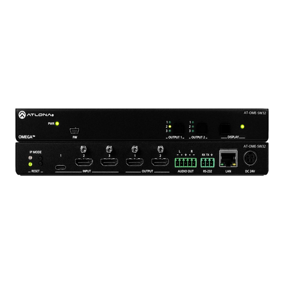
Panel Description AT-OME-SW32 OMEGA OUTPUT 1 OUTPUT 2 DISPLAY AT-OME-SW32 IP MODE RX TX RX TX RESET INPUT OUTPUT AUDIO OUT AUDIO OUT RS-232 RS-232 DC 24V PWR LED INPUT Illuminates green when receiving power. Connect the USB-C or HDMI sources to these ports. FW port OUTPUT Connect a mini USB cable from this port to a PC to... -
Page 10: Installation
Installation Captive Screw Connections RS-232 Connect to a control system for unit switching or to a display for power and audio display control. Pin out will be determined by the RS-232 cable and connect as RX (receive), TX (transmit) and (Ground). -
Page 11: Mounting Instructions
Installation Mounting Instructions The AT-OME-SW32 includes two mounting brackets and four mounting screws, which can be used to attach the units to any flat surface. 1. Remove the top 2 case screws on the side of the unit. 2. Align the mounting brackets to the side of the units. 3. -
Page 12: Connection Instructions
Installation Connection Instructions 1. Connect HDMI and USB-C Sources to the inputs. 2. Connect up to two HDMI displays to the outputs. 3. Connect the 2CH analog AUDIO OUT ports to a DSP, or audio amplifier (e.g. AT-GAIN-60). 4. *Optional* For control, connect to the 3-pin captive screw RS-232 port. 5. -
Page 13: Connection Diagram
Installation Connection Diagram Laptop Laptop E- ST A T- TE ST IN PU LI N AT-OME-SW32 Display Display AT-OME-SW32... -
Page 14: Webgui
WebGUI The AT-OME-SW32 includes a built-in webGUI, which allows easy remote management and control of all features. Follow the instructions below to access the webGUI. 1. Make sure that an Ethernet cable is connected between the LAN port on the AT-OME-SW32 and the network. 2. -
Page 15: Audio/Video Settings
webGUI Audio/Video Settings Select A/V Settings from the top navigation to adjust routing and video settings. Switching Mode Mirrored - When selected from the drop down menu, both HDMI outputs will pass source signal from the same selected source. This mode is selected by default. Matrix Mode - When selected, each HDMI Output will route source signals independently. - Page 16 webGUI Audio On - Unmutes the audio output signal, allowing audio to pass through the output. Off - Mutes the audio output signal of the selected port. No audio will pass when selected. NOTE: Analog audio output is de-embedded from HDMI output port 1. NOTE: Audio must be 2 channel to de-embed and is not downmixed from multichannel.
-
Page 17: Display
webGUI Display Select Display from the top navigation to adjust display control settings. NOTE: The Display page is only available when in mirrored or matrix switching w/static mode. Command: Power - Press to send the CEC power on or off command out through the HDMI ports. System Settings Display Auto Power - Sets the unit to send the display power on/off command to the output. - Page 18 webGUI TCP/IP Settings of Controlled Device (only available when IP is selected) IP Mode - Toggle telnet login mode between Non-Login and Login. If set to Login, a username and password will be required to control the controlled device via TCP/IP. IP Address - Sets to the IP of the controlled device/display.
-
Page 19: Edid
webGUI RS-232 Select RS-232 from the top navigation to adjust the zone control parameters for the RS-232 port. RS-232 Parameter Setting Zone - Select the baud rate, data bit, parity, and stop bit to match the display’s parameters. Defaults are 115200, 8, None, and 1. -
Page 20: Config
webGUI Config Select Config from the top navigation to update the admin password. Users Admin Password - Update the admin password for the switcher. Only the admin password may be changed, the username will remain admin. NOTE: The passwords cannot contain any special characters. e.g. !@#$%/^&*\?+-;’”. Once the new password has been entered, press the Save button to make the password live. -
Page 21: System
webGUI System Select System from the top navigation to adjust network and system options. Network MAC Address - Displays the MAC address of the unit. IP Mode - Switch between static and DHCP IP modes. IP, Netmask, Gateway - This will display the unit’s current DHCP IP settings. When set to static, fill in the IP address, netmask, and gateway. -
Page 22: Appendix
Appendix Configuration and Setup Guide This section will provide a step by step guide for basic set up and configuration for A/V routing and control. Installation The AT-OME-SW32 includes two mounting brackets and four mounting screws, which can be used to attach the units to any flat surface. -
Page 23: Configuration
Appendix 5. Connect a network switch to the LAN port, for IP control, system configuration, or Ethernet routing. 6. Connect the included DC 24V power supply to the power port. 7. Connect the included IEC power cord from the power supply to a compatible power outlet. Configuration Configuration will be done through the webGUI. -
Page 24: Control
Appendix 6. The SW32 will have EDID on pass through, with Output 1 downscaling 4K signal to 1080p automatically. To change the settings on this, go to the EDID page. a. Select EDID from the top menu. b. Select the internal or saved EDID from the drop down menu next to the corresponding port. c. - Page 25 Appendix d. Select Display from the top menu. e. Set the Auto power on/off parameters. Defaults are set to turn the display on/off after 15 seconds of signal loss or gain and to wait 10 seconds between on and off commands being sent after an on/off event. Select RS-232 from the Control Type drop down menu.
- Page 26 Appendix NOTE: Currently only the first column is used. The second column will be for a future feature update. d. Set the IP information and mode to match the display’s current settings. IP Mode will be default Non- Login, but can be set to login mode which will require the Username and Password to be entered in the corresponding fields to match the display’s parameters.
-
Page 27: Specifications
Appendix Specifications Connectors, Controls, and Indicators HDMI IN 2 - Type A, 19-pin female HDMI OUT 2 - Type A, 19-pin female USB-C IN 1 - USB Type-C v3.1, 24-pin female, AV input (Alternate Mode) 1 - Mini-USB, 5-pin female AUDIO OUT 1 - 5-pin captive screw, balanced / unbalanced 2-channel RS-232... - Page 28 Appendix Signal HDMI HDMI 2.0 CEC Support HDCP Temperature Fahrenheit Celsius Operating 32 to 122 0 to 50 Storage -4 to 140 -20 to 60 Humidity (RH) 20% to 60%, non-condensing Power Operational 6.98 W Idle 2.85 W Supply Input: 100 - 240 V AC, 50/60 Hz Output: 24 V / 2.7A DC Dimensions Inches...
- Page 29 Toll free US International atlona.com 877.536.3976 41.43.508.4321 • • © 2019 Atlona Inc. All rights reserved. “Atlona” and the Atlona logo are registered trademarks of Atlona Inc. All other brand names and trademarks or registered trademarks are the property of their respective owners. Pricing, specifications and availability subject to change without notice.
Need help?
Do you have a question about the Atlona Omega AT-OME-SW32 and is the answer not in the manual?
Questions and answers