Panduit ATLONA AT-UHD-SW-510W Solutions Setup And Configuration Manual
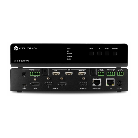
4k/uhd five-input universal matrix switcher with wireless presentation link
Hide thumbs
Also See for ATLONA AT-UHD-SW-510W:
- Manual (121 pages) ,
- Installation manual (17 pages) ,
- Manual (116 pages)

Related Manuals for Panduit ATLONA AT-UHD-SW-510W


Summary of Contents for Panduit ATLONA AT-UHD-SW-510W
- Page 1 4K/UHD Five-Input Universal Matrix Switcher with Wireless Presentation Link Solution Setup and Configuration Guide Atlona Manuals AT-UHD-SW-510W Switchers...
- Page 2 Version Information Version Release Date Notes Jul 2019 Initial release AT-UHD-SW-510W...
-
Page 3: Table Of Contents
Table of Contents Introduction Solution Setup and Configuration Guide Input Auto Switching Display Control CEC Control RS-232 Control Configuring IP Control Scheduling Display Operation Times Trigger Port Wiring Configuration using the Web GUI Relay Port Wiring Operation Configuration using the Web GUI AT-UHD-SW-510W... -
Page 4: Introduction
Introduction Welcome to the AT-UHD-SW-510W Solution Setup and Configuration Guide. This document covers the following topics: • Input Auto Switching This section explains how to configure the AT-UHD-SW-510W to automatically switch inputs, when sources are connected or disconnected. • Display Control The AT-UHD-SW-510W provides control of display (sink) devices through CEC, RS-232, or IP protocols. -
Page 5: Solution Setup And Configuration Guide
Solution Setup and Configuration Guide USB-C INPUT DISPLAY Input Auto Switching HDMI 3 The AT-UHD-SW-510W provides auto-switching capability, which will automatically switch the input to the most HDMI 4 BYOD recently-connected or powered source, if a so another source is powered-down or disconnected. For example, if the AT-UHD-SW-510W connection sequence for three separate sources is: DP IN 2 >... - Page 6 Solution Setup and Configuration Guide 5. Click Display in the menu on the left side of the window. 6. Locate the AutoSwitch check box, under the Control window group. 7. Click this check box to enable auto-switching. When auto-switch is enabled, a check mark will appear in this box.
-
Page 7: Display Control
Solution Setup and Configuration Guide Display Control The following section cover display control using the following methods: • • RS-232 • CEC Control Consumer Electronics Control (CEC) is the simplest method when working with a consumer display. Note that the display must have CEC enabled to receive CEC messages. - Page 8 Solution Setup and Configuration Guide CEC Control over HDBaseT a. Connect a category cable (CAT-5e or better) from the HDBaseT OUT port on the AT-UHD-SW-510W to a compatible receiver. The example below uses an AT-UHD-100CE-RX-PSE. b. Connect an HDMI cable from the HDMI OUT port on the receiver to the HDMI input on the display device. PL A D IS IN PU...
- Page 9 Solution Setup and Configuration Guide 2. Launch a web browser. 3. In the address bar, type the IP address of the AT-UHD-SW-510W. NOTE: If using AMS and the AT-UHD-SW-510W is running 2.4.0 or greater, click on the device within AMS to access the web interface. 4.
- Page 10 Solution Setup and Configuration Guide If the display does not respond, check the following: • Verify that CEC is enabled on the display device. • Verify the integrity of the HDMI cable. Try connecting a different HDMI cable between the AT-UHD-SW-510W and the display device.
-
Page 11: Rs-232 Control
Solution Setup and Configuration Guide RS-232 Control The AT-UHD-SW-510W can be connected directly to the display, using these ports, or a receiver, such as the AT- UHD-100CE-RX-PSE can be used to extend these signals to a remote display, up to 330 feet (100 meters) away. No external control system is required. - Page 12 Solution Setup and Configuration Guide Controlling a Display over HDBaseT PL A D IS IN PU U SB Display AT-UHD-SW-510W 1 0 W W -5 D -S -U H se T AT-UHD-100CE-RX-PSE 1. Connect an Ethernet cable from the HDBaseT OUT port on the AT-UHD-SW-510W to the HDBaseT IN port on USB-C the AT-UHD-EX-100CE-RX-PSE.
- Page 13 Solution Setup and Configuration Guide RS-232 Control Configuration Once the AT-UHD-SW-510W is connected, either directly or using an extender, use the following procedure to configure RS-232 control. 1. Launch a web browser. 2. In the address bar, type the IP address of the AT-UHD-SW-510W. NOTE: If using AMS and the AT-UHD-SW-510W is running 2.4.0 or greater, click on the device within AMS to access the web interface.
- Page 14 Solution Setup and Configuration Guide 7. Scroll down and locate the RS-232 section. a. If the RS-232 cable is connected directly from the AT-UHD-SW-510W to the display, then click the RS232 Mode drop-down list and select Local RS232 Only. b. If the RS-232 cable is connected to a remote extender, over HDBaseT, then click the RS232 Mode drop- down list and select HDBaseT RS232 Only.
- Page 15 Solution Setup and Configuration Guide 8. Click the Baud Rate, Data Bits, Parity, and Stop Bits drop-down list to set the values required by the control system. If these values do not match the RS-232 settings of the control system, then RS-232 control will not function properly.
- Page 16 Solution Setup and Configuration Guide HEX Command Strings a. An example hexadecimal power-on command for a display might be: \xBE\xEF\x03\x06\x00\xBA\xD2\x01\x00\x00\x60\x01\x00\x0D Consult the display documentation for the correct command strings. b. Make sure the command string is terminated correctly. In most cases, a CR (carriage return) should be specified.
-
Page 17: Configuring Ip Control
Solution Setup and Configuration Guide Configuring IP Control Display control can also be performed over IP. The steps are similar to the HDBaseT RS-232 setup, except that an Ethernet cable is connected between the LAN port on the extender and the display device. The following example shows how to extend IP control, using the AT-UHD-100CE-RX-PSE. - Page 18 Solution Setup and Configuration Guide 3. Launch a web browser. 4. In the address bar, type the IP address of the AT-UHD-SW-510W. NOTE: If using AMS and the AT-UHD-SW-510W is running 2.4.0 or greater, click on the device within AMS to access the web interface. 5.
-
Page 19: Scheduling Display Operation Times
Solution Setup and Configuration Guide Scheduling Display Operation Times The AT-UHD-SW-510W can be configured to automatically power-on or power-off a display during specified times and days of the week. Time must be specified in Universal Coordinated Time (UTC) format. Note that discrete calendar dates cannot be specified. -
Page 20: Trigger Port
Configuration using the Web GUI Configuration of the TRIGGER I/O port can be done through the web GUI or using API commands. Refer to the Application Programmers Interface, on the Atlona AT-UHD-SW-510W product web page, for more information. 1. Launch a web browser. - Page 21 Solution Setup and Configuration Guide 4. Click the Submit button or press the ENTER key on the keyboard. 5. Click Display in the menu on the left side of the window. 6. Locate the Trigger I/O section. 7. Click the desired checkboxes for the desired operation. By default, both Enable Power Off and Enable Power On are checked (enabled).
-
Page 22: Relay Port
Solution Setup and Configuration Guide Relay Port The AT-UHD-SW-510W provides a RELAY port, which provides a control interface for screens, curtains, and or other devices. Wiring The RELAY connector is wired to a pair of single-pole single-throw (SPST) relays, as shown below, providing two independent switches and a common (COM) connection. -
Page 23: Configuration Using The Web Gui
Configuration using the Web GUI Configuration of the RELAY port can be done through the web GUI or using API commands. Refer to the Application Programmers Interface, on the Atlona AT-UHD-SW-510W product web page, for more information. 1. Launch a web browser. - Page 24 Toll free US International atlona.com 877.536.3976 41.43.508.4321 • • © 2019 Atlona Inc. All rights reserved. “Atlona” and the Atlona logo are registered trademarks of Atlona Inc. All other brand names and trademarks or registered trademarks are the property of their respective owners. Pricing, specifications and availability subject to change without notice.
Need help?
Do you have a question about the ATLONA AT-UHD-SW-510W and is the answer not in the manual?
Questions and answers