Panduit ATLONA AT-UHD-SW-510W Manual
4k/uhd five-input universal matrix switcher with wireless presentation link
Hide thumbs
Also See for ATLONA AT-UHD-SW-510W:
- Manual (121 pages) ,
- Solutions setup and configuration manual (24 pages) ,
- Installation manual (17 pages)

Related Manuals for Panduit ATLONA AT-UHD-SW-510W


Summary of Contents for Panduit ATLONA AT-UHD-SW-510W
- Page 1 4K/UHD Five-Input Universal Matrix Switcher with Wireless Presentation Link Atlona Manuals AT-UHD-SW-510W Switchers...
- Page 2 Version Information Version Release Date Notes Dec 2017 Initial release Feb 2018 Updated to reflect firmware 1.0.1 Apr 2018 Updated to reflect firmware 1.0.3 May 2018 Updated to reflect firmware 1.1.0 Jul 2018 Updated to reflect firmware 1.1.1 Aug 2018 Updated to reflect firmware 1.2.0 Sep 2018 Updated to reflect firmware 1.2.1...
- Page 3 Welcome to Atlona! Thank you for purchasing this Atlona product. We hope you enjoy it and will take a extra few moments to register your new purchase. Registration only takes a few minutes and protects this product against theft or loss. In addition, you will receive notifications of product updates and firmware.
- Page 4 Atlona, Inc. (“Atlona”) Limited Product Warranty Coverage Atlona warrants its products will substantially perform to their published specifications and will be free from defects in materials and workmanship under normal use, conditions and service. Under its Limited Product Warranty, Atlona, at its sole discretion, will either: •...
- Page 5 Atlona, Inc. (“Atlona”) Limited Product Warranty • Damage, deterioration or malfunction resulting from the installation or removal of this product from any installation, any unauthorized tampering with this product, any repairs attempted by anyone unauthorized by Atlona to make such repairs, or any other cause which does not relate directly to a defect in materials and/or workmanship of this product.
- Page 6 Important Safety Information 9. Do not defeat the safety purpose of a polarized CAUTION or grounding-type plug. A polarized plug has two RISK OF ELECTRIC SHOCK blades with one wider than the other. A grounding DO NOT OPEN type plug has two blades and a third grounding CAUTION: TO REDUCT THE RISK OF prong.
-
Page 7: Table Of Contents
Table of Contents Introduction Features Package Contents Panel Description Front Panel - Revision A and B Front Panel - Revision C Rear Panel - All Revisions Installation Audio Trigger Relay Connection Instructions Connection Diagram IP Configuration Switching the IP Mode Using the Front Panel Getting the IP Address Getting the IP Address without a Display Setting the IP Address using the Web GUI... - Page 8 Table of Contents 802.1X Authentication Using Wifi Using Ethernet Setting Access Point Range RS-232 Control Determining the Port Type Cable Assembly Pass-through mode Control mode The Web GUI Introduction to the Web GUI Menu Bar Info General page System page Status page Splash Screen page Splash Screen...
-
Page 9: Introduction
Introduction The Atlona AT-UHD-SW-510W is a 5×2, multi-format matrix switcher with wireless presentation capability. It provides universal BYOD (bring your own device) compatibility with HDMI, DisplayPort, and USB-C inputs, plus wireless connectivity for mobile devices. The SW-510W is HDCP 2.2 compliant, and features matrixed or mirrored HDMI and HDBaseT outputs. -
Page 10: Panel Description
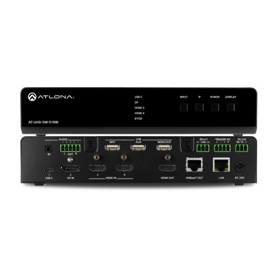
Panel Description NOTE: As of April 2019, Revision C is being shipped. Hardware revisions A and B were shipped prior to April of 2019. However, all hardware revisions support the latest version of firmware. Front Panel - Revision A and B USB-C INPUT DISPLAY... -
Page 11: Rear Panel - All Revisions
Panel Description Rear Panel - All Revisions AUDIO RELAY TRIGGER I/O RS-232 WiFi MIRACAST C1 COM C2 HDBaseT OUT USB-C IN DP IN HDMI IN HDMI OUT DC 24V AUDIO IN USB-C Connect a 3.5 mm mini-stereo cable from an analog Connect a USB-C cable from this port to a USB-C audio source to this connector. -
Page 12: Installation
Installation Audio The AUDIO OUT connector on the AT-UHD-SW-510W provides a separate output for balanced audio using XLR connectors. Use the included 5-pin captive-screw terminal block. Balanced audio connections use two signal wires and a ground to minimize interference in audio signals. Unbalanced output audio is not supported. Trigger The TRIGGER I/O port allows voltage-controlled devices, such as an occupancy sensor, to be connected to the AT- UHD-SW-510W. -
Page 13: Relay
Installation Relay The AT-UHD-SW-510W provides a RELAY port, which allows the control of screens, curtains, and other devices. Use a 48 V DC relay with no more than 1 A current draw. When the AT-UHD-SW-510W is powered-on or rebooted, C1 and C2 are set to the Normally Open (NO) state. AT-UHD-SW-510W... -
Page 14: Connection Instructions
Installation Connection Instructions 1. Connect a USB-C cable from a source to the USB-C (1) port. 2. Connect a DisplayPort cable from a source to the DP IN (2) port. 3. Connect up to two UHD/HD sources, using HDMI cables, to the HDMI IN (3) and HDMI IN (4) ports. 4. -
Page 15: Connection Diagram
Installation Connection Diagram AT-VGW-250 DI SP W ER IN PU B- C AT-UHD-SW-510W 10 W W -5 D -S A T- AT-UHD-EX-100CE-RX-PSE AT-VTP-800-WH se T Tablet (BYOD) Miracast™ Laptop Laptop UHD/HD Display Laptop AT-UHD-SW-510W... -
Page 16: Ip Configuration
Installation IP Configuration The AT-UHD-SW-510W is shipped with DHCP enabled. Once connected to a network, the DHCP server (if available), will automatically assign an IP address to the unit. Use an IP scanner, along with the MAC address on the bottom of the unit, to identify both the unit and its IP address on the network. -
Page 17: Setting The Ip Address Using The Web Gui
Installation 4. Remove the USB drive from the AUX port insert the drive into an available USB port on a computer. 5. Two files will be present on the USB drive. One file is formatted for Windows and the other is formatted for Linux. Windows: AtlonaReport-Win-GWB-20170821200241.txt Linux:... -
Page 18: Auto Ip Mode
Installation 4. Click the Mode drop-down list and select DHCP, Static, or Factory Static. Refer to the Networking page (page 91) for more information. If set to Factory Static, then the IP settings will be set to: IP Address = 192.168.1.254, Network Mask = 255.255.0.0, Gateway = 192.168.1.1. -
Page 19: Basic Operation
Basic Operation Boot Sequence 1. After the power supply has been connected to the AT-UHD-SW-510W, the input indicators on the front panel will begin to flash, in an up-and-down pattern, as shown by the arrows. Input indicators USB-C INPUT POWER DISPLAY HDMI 3 HDMI 4... -
Page 20: Selecting The Input
Basic Operation Selecting the Input Press the INPUT button to cycle through each of the available inputs on the unit. If the unit is powered-off, then powered-on, the AT-UHD-SW-510W will set the default input to BYOD. USB-C INPUT POWER DISPLAY HDMI 3 HDMI 4 BYOD... -
Page 21: Setting The System Date And Time
Basic Operation Setting the System Date and Time The AT-UHD-SW-510W uses the internal clock to store the current date and time. When setting the time and date, Universal Coordinated Time (UTC) must be used. Manual Adjustment 1. Login to the web GUI. Refer to Introduction to the Web GUI (page 71) for more information. -
Page 22: Using An Ntp Server
Basic Operation Using an NTP Server 1. Login to the web GUI. Refer to Introduction to the Web GUI (page 71) for more information. 2. Convert the local time to 24-hour time. 3. Click System in the side menu bar. 3. -
Page 23: The Splash Screen
Basic Operation The Splash Screen The illustration below, identifies each portion of the Splash Screen. The vertical position of the Panel can be adjusted using the Y Offset feature. Displaying Metadata (page 25) can be enabled or disabled. The background image can also be changed. - Page 24 Basic Operation 4. Make the desired changes to each field, as shown below. Note that the Subtitle field is assigned the value {name}. This value is a system value, which represents the name of this specific device. Other system values are available and can be placed in any of these fields. To display a list of available system values, click Legend.
-
Page 25: Displaying Metadata
Basic Operation Description {wlan0} The IP address of the AT-UHD-SW-510W when using a wireless connection. {version} Displays the Master Firmware version. Displays the Access Point password, when the AT-UHD-SW-510W is configured {password} as an Access Point. If configured as an Access Point, this tag will be populated with the selected password. - Page 26 Basic Operation Metadata Welcome Name: SW510-E573 SW510-E753 Model: SW510W Date: 08/29/2018 Wired IP: 10.0.1.83 To being your presentation: Version: 2.3.3 LED - Grey: /opt/tomcat/webapps/ROOT/static/images/icons/led_grey_small.png Connect wired: Connect wirelessly: LED - Grey: <image src=”{url:led_grey}”> LED - Green: /opt/tomcat/webapps/ROOT/static/images/icons/led_green_small.png Connect the HDMI, USB-C, Search for SW510-E753 LED - Green: <image src=”{url:led_green}”>...
-
Page 27: Displaying The Wireless Password
Basic Operation Displaying the Wireless Password This feature is applicable only when the AT-UHD-SW-510W is configured as an Access Point. The wireless password can be displayed as part of any text field on the splash screen. To do this, insert the {password} tag as part of a text string. -
Page 28: Changing The Splash Screen Image
Basic Operation Changing the Splash Screen Image The background image can be changed to any of the three included splash screens, shown below. In addition, custom images may be uploaded and used instead of the factory splash screens. Splash screen cycling, which is outlined below, can prevent image persistence which is the equivalent of image burn-in on CRT and plasma computer monitors. -
Page 29: Resetting Splash Screen Images
Basic Operation Uploading a custom image Any one of the splash screens or the loading screen can be replaced with a custom image. 1. Launch a web browser and enter the IP address of the AT-UHD-SW-510W in the address bar. 2. -
Page 30: Html Splash Screens
Basic Operation HTML Splash Screens HTML-based splash screens can be used to create content-rich splash screens. This section provides details on creating and uploading an HTML splash screen. Familiarity with HTML is assumed. The AT-UHD-SW-510W comes a default HTML splash screen, which can be downloaded from the Resources tab of the product page on the web. - Page 31 Basic Operation 2. Save the file as index.html_template. This file name must be used. 3. Combine the index.html_template file along with all required external images/files into a .zip file called html.zip. IMPORTANT: The index.html_template file must reside in the root directory, within the html. zip file.
-
Page 32: Resetting The Html Splash Screen
Basic Operation 8. Click the Upload button. 9. Select the html.zip file, then click Open, to upload the file to the AT-UHD-SW-510W. 10. Click the Save button to commit changes. Resetting the HTML Splash Screen IMPORTANT: The Reset (Reset HTML) button will delete any loaded HTML data and replace it with the default HTML page that comes with the AT-UHD-SW-510W. -
Page 33: Wireless Configuration
Basic Operation Wireless Configuration ® The AT-UHD-SW-510W features a wireless gateway, providing convenient Wi-Fi connectivity for iOS, Android, Mac, Chromebook, or Windows-based devices, and a built-in web GUI. In addition, the AT-UHD-SW-510W can be configured as a wireless access point (AP). The addition of a built-in firewall provides control of incoming and outgoing network traffic. - Page 34 Basic Operation 9. Click the Hide Password on OSD check box to prevent the password from being displayed. 10. Click the Rotate WiFi Password check box to allow the AT-UHD-SW-510W to generate a new random password. This feature can be used to provide an extra level of security. Dynamically rotating the password decreases the risk that unauthorized clients will not have access to the AT-UHD-SW-510W if the current password is “leaked”...
- Page 35 Basic Operation Firewall Mode (optional) This feature allows control of incoming and outgoing network traffic, from/to a network that is connected to the RJ45 connector on the AT-UHD-SW-510W. The AT-UHD-SW-510W provides the following firewall modes: Block Private Network, Block Internet, Block All, and None. If this feature is not desired, then the following steps can be skipped.
-
Page 36: Connect Mode
Basic Operation Connect Mode Use this mode to connect the AT-UHD-SW-510W to another wireless network. 1. Launch a web browser and enter the IP address of the AT-UHD-SW-510W in the address bar. 2. Login to the web GUI. Refer to Introduction to the Web GUI (page 71) for more information. - Page 37 Basic Operation 6. Select the desired wireless network from the pop-up dialog box. 7. Click the OK button to accept the selection and dismiss the dialog box. Click the Cancel button to return to close the dialog and return the Wifi tab. Enter the password for the wireless network in the Password field.
- Page 38 Basic Operation Once a successful connection has been established, the Status field will display Connected, as shown below. The following table provides a list of possible status messages. State Description Connected The AT-UHD-SW-510W is connected to the wireless network. Not Connected Unsuccessful connection.
-
Page 39: Casting
Basic Operation Casting ® ™ ® The AT-UHD-SW-510W interface provides the ability to transmit (“cast”) the screen of any iOS , Android , macOS Chromebook, or Windows device over Wi-Fi, without having to install a separate application or driver. The AT-UHD- SW-510W can serve as an integrated, dual-band access point, or be networked into an existing Wi-Fi installation. - Page 40 Basic Operation 7. Tap the SSID from the list of devices. 8. Close the Control Center by either swiping down or pressing the Home button. 9. The image of the iOS device will now appear on the connected display. Note that depending upon the application, the image on the screen can be rotated.
- Page 41 Basic Operation AirPlay can be used to either mirror or extend the Mac display. • Mirroring Click the AirPlay icon in the menu bar and select the desired display to be mirrored. • Extending Click the AirPlay icon and select “Use As Separate Display” from the list of displays, to extend the Desktop to another display.
-
Page 42: Microsoft Miracast
Basic Operation Microsoft Miracast Miracast is a wireless protocol that allows content to be transmitted from laptops and other mobile devices to ® displays. The latest release of Microsoft Windows 10 supports Miracast. Displaying Miracast devices can be done in more than one way. Three methods are discussed below. The first method is the most direct method. -
Page 43: Google Chrome
Basic Operation Google Chrome 1. Make sure both the AT-UHD-SW-510W and the “casting” computer are on the same network. 2. Launch Google Chrome. 3. Click the icon, in the upper right corner of the Chrome browser. 4. Click the Cast... option from the drop-down menu. 5. - Page 44 Basic Operation Chrome will immediately begin casting to the AT-UHD-SW-510W. Note that if Moderator mode is enabled, this cast will be placed in the Users table queue. Refer to Using Moderator Mode (page 55) for more information. 6. Adjust the volume (if audio is present), by clicking and dragging the slider control. In addition, either Remote screen or Both screens can be selected from the Show fullscreen videos on drop-down list.
-
Page 45: Google Home
Basic Operation Google Home 1. Make sure both the AT-UHD-SW-510W and the mobile device are on the same network. 2. On your mobile device, press and hold the icon. The Cast screen context menu will be displayed. 3. From the Mirror device screen, tap the button. -
Page 46: Advanced Operation
Advanced Operation Matrix Modes The AT-UHD-SW-510W features two matrix modes: Matrix Mode and Matrix Mode with static route. Enabling matrix mode provides the ability to use AT-UHD-SW-510W in video codec / conference applications, using a dual-presentation mode. Matrix Mode This mode allows the AT-UHD-SW-510W to independently switch between any input or both outputs. Following the instructions below to configure Matrix Mode. - Page 47 Advanced Operation Example diagram illustrating a Matrix Mode application. I OUT AT-VTP-800 P OUT -250 AT-V AT-UHD-SW-510W AT-VGW-250 Network Switch DI SP W ER IN PU B- C AT-UHD-EX-100CE-RX-PSE 10 W W -5 D -S A T- Tablet (BYOD) t o p t o p L a p L a p...
-
Page 48: Matrix Mode W/ Static Route
Advanced Operation Matrix Mode w/ Static Route This mode allows the AT-UHD-SW-510W to be integrated with a video conference system. In this mode, both static input and output routing are specified. Auto switching will be enabled. However, the specified static input will be removed from the auto-switching pool. - Page 49 Advanced Operation Example diagram illustrating a Matrix Mode application. AT-UHD-SW-510W Network Switch DI SP W ER IN PU B- C AT-UHD-EX-100CE-RX-PSE 10 W W -5 D -S A T- se T n t e E n d F a r Codec Tablet e r a...
-
Page 50: Selecting The Audio Input
Advanced Operation Selecting the Audio Input By default, the AT-UHD-SW-510W will use the digital audio (if present) from the USB-C IN, DP IN, or HDMI IN ports and output the audio over the HDMI OUT and/or HDBaseT OUT ports. However, an external analog source can also be used. -
Page 51: Airplay Bluetooth Discovery
Advanced Operation AirPlay Bluetooth Discovery The AT-UHD-SW-510W supports Bluetooth®-assisted device discovery. A Bluetooth adapter is required, but not included. Atlona recommends Plugable and Kinivo Bluetooth 4.0 adapters. IMPORTANT: Bluetooth discovery is applicable only to Apple devices and is used for device discovery on networks, such as corporate networks, where mDNS is not permitted. -
Page 52: Airplay / Miracast P2P Pin Codes
Advanced Operation AirPlay / Miracast P2P PIN Codes The AT-UHD-SW-510W can be configured to prompt for a PIN code, before a BYOD device connects with either AirPlay or Miracast P2P. When the this option is enabled, a PIN code will be displayed on the screen when an AirPlay or Miracast device attempts to connect to the AT-UHD-SW-510W. - Page 53 Advanced Operation Wireless Configuration (page 33) 5. Connect the AirPlay/Miracast P2P device to the AT-UHD-SW-510W. Refer to for more information. 6. Begin casting to the AT-UHD-SW-510W. When the device attempts to connect to the AT-UHD-SW-510W, a PIN code will be displayed on the screen that is connected to the device. Refer to the illustration on the next page, if necessary.
-
Page 54: Changing The Pin Timeout
Advanced Operation Changing the PIN Timeout By default, the AT-UHD-SW-510W will automatically generate a new PIN code for each new Wifi connection that is attempted. However, this value can also be set to regenerate every 15 minutes or 60 minutes. NOTE: The AT-UHD-SW-510W requires a minimum of 20 seconds to elapse before another PIN code is generated. -
Page 55: Using Moderator Mode
Advanced Operation Using Moderator Mode Moderator mode provides a layer of control when multiple clients are casting through the AT-UHD-SW-510W. The “moderator” can either allow or kick (remove) a client from casting content. Up to four users can be hosted in the Users table. - Page 56 Advanced Operation Once the devices have started casting, they will be displayed in the Users table, as shown in the example below. Devices will only appear in this table when they are casting. When devices are displayed in this table, an Allow and Kick button will also be available for each device.
- Page 57 Advanced Operation 6. Click the Allow button, on another connected device, to make that device the active casting device. It may take a few moments before the new casting device appears on the screen. NOTE: When an alternate device is selected to cast, by clicking the Allow button, the currently active casting device will be removed (“kicked”) from the Users table.
-
Page 58: Scheduling Display Operation Times
Advanced Operation Scheduling Display Operation Times The AT-UHD-SW-510W can be configured to automatically power-on or power-off a display during specified times and days of the week. Note that discrete calendar dates cannot be specified. 1. Login to the web GUI. Refer to Introduction to the Web GUI (page 71) for more information. -
Page 59: 802.1X Authentication
Advanced Operation 802.1X Authentication 802.1X is a server-based port authentication which restricts unauthorized (rogue) clients from connecting to a Local Area Network through a public port. In its simplest form, 802.1X usually involves three parties: supplicant (client device), authenticator (Ethernet switch or WAP), and an authentication server. Before the device is permitted on the network, port communication is restricted to Extensible Authentication Protocol over LAN (EAPOL) traffic. - Page 60 Advanced Operation 4. Click the 802.1x Enable checkbox. If selecting Access Point mode, scroll down within in the Wifi tab, and click the Enable NOTE: 802.1x AP Mode checkbox. 5. Enter the required credentials in the Identity and Password fields. 6.
-
Page 61: Using Ethernet
Advanced Operation Using Ethernet 1. Login to the web GUI. Refer to Introduction to the Web GUI (page 71) for more information. 2. Click Administration > Networking from the menu bar on the left. 3. Under the Ethernet tab. Make sure the proper network mode is set: DHCP, Static IP, or Factory Static. IP Configuration (page 16) Refer to for more information. -
Page 62: Setting Access Point Range
Advanced Operation Setting Access Point Range The USB Wifi antanna power can be adjusted to control the Access Point signal strength. This is particularly useful in a multi-conference room environment to prevent the Access Point signal from “bleeding” into other rooms. 1. -
Page 63: Rs-232 Control
Advanced Operation RS-232 Control NOTE: If the AT-UHD-SW-510W will be controlled from a computer running a terminal program, a DB-9-to-USB cable should be purchased/obtained. The AT-UHD-SW-510W provides an RS-232, allowing the unit to be managed using a control system. RS-232 is serial data protocol that allows Data Terminal Equipment (DTE) devices, such a computer or control system, to communicate with Data Communication Equipment (DCE) devices, such as the AT-UHD-SW-510W or a display. -
Page 64: Cable Assembly
Advanced Operation Cable Assembly When connecting a DTE device to a DCE device, a straight-through cable should be used. A straight-through cable is wired in such a way that the pins on one side of the cable are connected to the corresponding pins on the opposite side of the cable, as shown in the table below. -
Page 65: Pass-Through Mode
Advanced Operation Pass-through mode In pass-through mode, RS-232 commands are sent to the AT-UHD-SW-510W and then transmitted over HDBaseT to a receiver unit, and then to the display (sink) device. 1. Connect the RS-232 cable between the control system and the RS-232 port on the AT-UHD-SW-510W. Refer to Cable Assembly (page 64) for instructions on preparing the cable. - Page 66 Advanced Operation 3. Connect an RS-232 cable between the display (sink) and the receiver. 4. Launch a web browser and login to the web GUI. Refer to Introduction to the Web GUI (page 71) for more information. The factory-default username and password are listed below: Username: admin Password: Atlona 5.
- Page 67 Advanced Operation 8. Click the Baud Rate, Data Bits, Parity, and Stop Bits drop-down list to set the values required by the control system. If these values do not match the RS-232 settings of the control system, then RS-232 control will not function properly.
-
Page 68: Control Mode
Advanced Operation Control mode In control mode, RS-232 commands are sent from a computer or control system (DTE) to the AT-UHD-SW-510W (DCE). This method allows direct control of the switcher for routing, IP configuration, powering-on / powering-off and other functions. NOTE: The RS-232 port on the AT-UHD-SW-510W runs at a baud rate of 115200. - Page 69 Advanced Operation 4. Click the Control Type drop-down list and select RS-232. 5. Scroll down and locate the RS-232 section. Click the RS232 Mode drop-down list and select Local RS232 Only. The RS-232 section is available only if the Control Type is set to RS-232. 6.
- Page 70 Advanced Operation 7. Click the Manufacturer drop-down list to select the manufacturer of the device that is being controlled. 8. Continue fine-tuning the device selection by clicking the Products and Model drop-down lists. Once all fields have been set to the proper values, the AT-UHD-SW-510W will populate the ON, OFF, Volume+, Volume-, and Mute fields with the commands used by that device.
-
Page 71: The Web Gui
The Web GUI Introduction to the Web GUI The AT-UHD-SW-510W includes a built-in web GUI. Atlona recommends that the web GUI be used to set up the AT-UHD-SW-510W, as it provides intuitive management of all features. Follow the instructions below to access the webGUI. -
Page 72: Menu Bar
The Web GUI 7. The Info page will be displayed. Menu Bar The window on the left side of the screen is the is the menu bar and lists all available menus. Click on the desired menu item to open that page. In this example, clicking Display, in the menu bar, will display the Display page. -
Page 73: Info
The Web GUI Info After logging in, the Info page will be displayed. The Info page provides basic information about the receiver, including the model name, software version, input video timing, and the device being using as the transmitter. Model Name The model SKU of this product. -
Page 74: General Page
The Web GUI General page Name This is the hostname of the unit. Enter the desired name of the AT-UHD-SW-510W in this text field. Include the {id} tag to use the last four digits of the hardware MAC address. Hostnames can contain alphabetic and numeric characters. -
Page 75: System Page
The Web GUI System page Display name The name of the display, provided in the Name field of the General tab. Refer to General page (page 74) for more information. Restart Click this button to reboot the AT-UHD-SW-510W. Shutdown Click this button to shut down the AT-UHD-SW-510W. This should always be performed before disconnecting power from the unit. - Page 76 The Web GUI Firmware Version The version of (MCU) firmware that the AT-UHD-SW-510W is running. Always make sure to check the AT-UHD-SW- 510W product page, on the Atlona web site, for the latest version of firmware. Firmware Check Click the Check button to check for the latest version of firmware. Each time the unit is rebooted, this feature is performed, automatically.
-
Page 77: Status Page
The Web GUI Status page This page provides a information about the current state of the AT-UHD-SW-510W, such as IP information, memory usage, casting devices, active sources, date/time, and various other settings. AT-UHD-SW-510W... -
Page 78: Splash Screen Page
The Web GUI Splash Screen page Splash Screen Type Click this drop-down list to select the type of splash screen. Show Meta Data Click this check box to display metadata on the splash screen. Show Panel Check (enable) this box to display the panel, containing connection instructions and other information. Y Offset Sets the up-and-down position of the overlay panel, on the screen. -
Page 79: Images
The Web GUI Column #2 The text positioned in the right-hand column. The default text is “Connect wirelessly: Connect the Wi-Fi network”, entercode, and enable AirPlay, Google Cast™, or Miracast”. Footer By default, this field provides a link to how casting works on different operating systems (www.atlona.com/casting). This field can be modified to contain a different URL, if desired. -
Page 80: Routing Page
The Web GUI Routing page Input Selection USBC, DP, HDMI3, HDMI1, BYOD Click the desired button to set the auto-switch input. Matrix Switching Matrix Switch Click this drop-down list to select the desired matrix mode. Refer to Matrix Modes (page 46) for more information. -
Page 81: Display Page
The Web GUI Display page Control AutoSwitch Click this box to enable or disable auto-switching. When this box is checked, the AT-UHD-SW-510W will automatically switch inputs when the new device is connected. To disable auto-switching, uncheck this box. Display Control Method Click this drop-down list to select the desired method of display control. - Page 82 The Web GUI Lamp Cool Down Timer (15 - 300 sec) Sets the projector lamp cool-down timer, in seconds. This value specifies the time interval that must elapse, after the display control “off” command is sent, before the display “power on” command can be sent. This feature is used to prevent the projector from missing a “power on”...
-
Page 83: Cec Commands
The Web GUI Once the countdown timer expires, the display will power off. Refer to the illustration below. Control Type Sets the control protocol for the connected display. Click this drop-down to select the control type. Available settings are CEC, IP, and RS-232. By default, CEC is selected for control of the display. IP and RS-232 can also be selected. -
Page 84: Trigger I/O
The Web GUI Trigger I/O This section defines how the TRIGGER port will respond to varying voltage levels. Either or both of the following conditions can be enabled or disabled. Enable Trigger On / Enable Trigger Off Uncheck the box to enable a power-off state when the trigger voltage is pulled from low to high. Check this box to enable a power-on state when the trigger voltage is pulled from low to high. - Page 85 The Web GUI Control Type : RS-232 When RS-232 is selected from the Control Type drop-down, both the HDBaseT RS-232 and RS-232/IP Commands section is displayed. RS232 Mode Click this drop-down list to select the RS-232 mode that will be affected by the Baud Rate, Data Bits, Parity, and Stop Bits settings.
- Page 86 The Web GUI RS-232/IP Commands Click the Manufacturer, Products, and Model drop-down lists to select the desired product. Note that only a minimal set of devices have been included. Once a device is selected, the ON, OFF, Volume+, Volume-, and Mute fields will be populated with the correct information for that device.
- Page 87 The Web GUI Control Type : IP When IP is selected from the Control Type drop-down, both the IP and RS-232/IP Commands section is displayed. IP Address Enter the IP address of the remote device. Port [0 - 65535] Enter the listening port for the remote device. Values from 0 through 65535 are valid. RS-232/IP Commands Click the Manufacturer, Products, and Model drop-down lists to select the desired product.
-
Page 88: Edid Page
The Web GUI EDID page EDID (Extended Display Identification Data) Displays the EDID assigned that is being used by each output. Press the Save button to save the EDID to a file. Inputs The Input column displays each of the inputs on the AT-UHD-SW-510W. Click the drop-down list, under the Selection column, to select the desired EDID to be used. -
Page 89: Administration Page
The Web GUI Administration page Telnet page The Telnet page provides an emulated terminal for entering commands. AT-UHD-SW-510W... -
Page 90: Moderator Page
The Web GUI Moderator page The Moderator page provides control of which device, that are casting, are permitted to display content. Refer to Using Moderator Mode (page 55) for more information. Enable Click this check box to enable or disable Moderator mode. If this box is checked, then Moderator mode is enabled. In order to monitor which devices are allowed to display content, this box must be checked before a device begins casting. -
Page 91: Networking Page
The Web GUI Networking page Use this page to configure network settings for the AT-UHD-SW-510W. This page is also used to configure Access Point and Connect to WiFi modes. Refer to the IT Network Deployment Guide for detailed information on configuring the AT-UHD-SW-510W in various network environments. - Page 92 The Web GUI IP Address Enter the desired IP address for the AT-UHD-SW-510W in this field. This field can only be changed when Mode is set to Static. Network Mask Enter the subnet mask in this field. This field can only be changed when Mode is set to Static. Gateway Enter the gateway (router) address in this field.
- Page 93 The Web GUI Access Point Power Level Sets the transmission power of the USB WiFi antennas. Click the drop-down list to select the power level. Available values are integers 0 through 13. Lower values will reduce transmission power of the USB WiFi antenna, thus limiting the range of the Access Point on the AT-UHD-SW-510W.
- Page 94 The Web GUI WiFi - Connect to WiFi Mode Mode Click this drop-down list to select the desired Wifi mode. Setting Description Select this option to configure the AT-UHD-SW-510W as a Wireless Access Point, Access Point allowing other wireless devices to connect to the same wired network as the AT- UHD-SW-510W.
- Page 95 The Web GUI Connecting to a Wifi Network 1. Select Connect to WiFi from the Mode drop-down list. 2. Click the Pick button to open the Pick a Wifi Network dialog box. 3. Click on the desired wireless network from the list. 4.
-
Page 96: Debug Page
The Web GUI Debug page Click the Download Logs button to download the debug logs. Debug logs are downloaded in a .zip file. Debug logs are used by Atlona Technical Support Engineers to identify functionality issues. 1. Click Debug on the side menu bar. 2. -
Page 97: User Accounts Page
The Web GUI User Accounts page This page allows the default password to be changed. 1. Click the Change button to display the Change Password dialog box. 2. Enter the new password in the Password field. 3. Re-enter the same password in the Repeat Password field. 4. -
Page 98: Advanced Page
The Web GUI Advanced page Provides options for advanced functionality. Telnet Enable Telnet Click this check box to enable or disable the Telnet protocol for the AT-UHD-SW-510W. When checked, Telnet is enabled. Telnet Authentication Click this check box to enable or disable the Telnet authentication. When checked, Telnet is enabled. When this feature is enabled, username and password credentials will be required at the beginning of the Telnet session. - Page 99 The Web GUI BYOD Max BYOD Time Click this drop-down list to select the desired time interval before the connected BYOD is automatically disconnected from the AT-UHD-SW-510W. Available options are 35 minutes to 5 hours. Kick User Click this button to disconnect the current BYOD. Airplay Bluetooth - Discovery Click this check box to enable Bluetooth discovery when using an Ethernet connection.
- Page 100 The Web GUI Front Panel (Revision C only) Lock Power Button Click check box to enable or disable the locking of the DISPLAY button on the front panel. Locking this button will prevent accidental pressing of the DISPLAY button and powering-off the unit. Front Panel (Revision A and B only) Arrow Buttons Click this drop-down list to define the functionality of the front-panel arrow buttons.
- Page 101 The Web GUI Firmware MCU Firmware Check the Upload button to upload the MCU firmware. Maintenance Allow Maintenance Window Check this box to enable maintenance mode. This feature can only be enabled if the local time has been set. Refer to Setting the System Date and Time (page 21) for more information.
-
Page 102: Pre-Release Page
The Web GUI Pre-Release page This page lists beta features, which are currently in the pre-release / testing stage. It should be noted that these features may not function reliably. AT-UHD-SW-510W... -
Page 103: Audio Page
The Web GUI The Web GUI Audio page Adjusts the output volume. Audio Click and drag this slider to adjust the output volume. Output is adjustable from -80 to 0 dB. Audio Input Click these drop-down lists to select the desired audio input source. If Analog is selected, then the analog audio source connected to the 3.5 mm AUDIO IN port will be heard on that output. -
Page 104: Event Viewer Page
The Web GUI The Web GUI Event Viewer page Displays a dynamic list of events, returned in JSON format. The image below, shows a list of sample events. AT-UHD-SW-510W... -
Page 105: Appendix
Appendix Updating the Firmware The following procedure outlines the firmware update procedure for the AT-UHD-SW-510W. This product can only be updated through the web GUI. WARNING: Do not physically reboot the system during the update process. Doing so may cause firmware file corruption and/or system instability. - Page 106 Appendix Upload button 8. During the update process, the following message will appear in the upper-right corner of the screen. Note that up to five minutes to complete. The unit will automatically reboot as part of the the update process may take update process.
- Page 107 Appendix Updating from Version 1.2.1-5 (or ealier) 1. Download the firmware file from https://atlona.com/product/at-uhd-sw-510w/. 2. Connect the computer, containing the firmware files, to the same network as the AT-UHD-SW-510W. 3. Press and release the IP button on the front panel. The IP address will appear on the connected display. NOTE: If using hardware revision A or B, simultaneously press and hold the INPUT and buttons on the front panel for five seconds, then release.
- Page 108 Appendix 9. The following message will appear at the top of the screen. Click the message or press the ESC key to return to the Login screen. Enter the login credentials. 10. Click Info on the side menu bar and check the Firmware Version. Firmware Version If the Firmware Version reads 1.1.05, then the firmware update process is complete.
- Page 109 Appendix 13. During the update process, the following message will appear in the upper-right corner of the screen. Note that up to five minutes to complete. The unit automatically reboots. the update process may take 14. After the firmware process has completed, the AT-UHD-SW-510W will automatically reboot and the following message will appear at the top of the screen: 15.
-
Page 110: Mounting Instructions
Appendix Mounting Instructions The AT-UHD-SW-510W can be mounted in different ways, based on the number of units that are being installed. The AT-UHD-SW-510W can be mounted in a rack or on/under any flat surface. NOTE: AT-UHD-510W-RM rack ears are sold separately. Contact Atlona for more information. Single-unit Rack Installation 1. -
Page 111: Dual-Unit Rack Installation
Appendix Dual-unit Rack Installation 1. Turn both units upside-down on a flat surface, next to each other, as shown. 2. Position the included mounting plates over the holes on the bottom of the enclosure. When attaching mounting plates, the countersink bevels on the mounting plate should face upward. Countersink bevel 3. -
Page 112: Flat Surface
Appendix Flat Surface 1. Turn the unit upside down, on a flat surface. 2. Position the included mounting plates over the pre-drilled holes on the bottom of the enclosure. When attaching mounting plates, the countersink bevels on the mounting plates should face upward. Countersink bevel 3. -
Page 113: Specifications
Appendix Specifications Connectors, Controls, and Indicators HDMI IN 2 - Type A, 19-pin female HDMI OUT 1 - Type A, 19-pin female DP IN 1 - 20-pin female USB-C IN 1 - USB Type-C v3.1, 24-pin female, AV input (Alternate Mode) 3 - USB 2.0 Type A for Wi-Fi®... - Page 114 Appendix Signal Maximum TMDS Clock 600 MHz (300 MHz over HDBaseT) HDMI HDMI 2.0* HDBaseT 10 Gbps † CEC Support HDCP 2.2 (wired device connections, only) * 18 Gbps supported for HDMI 2.0 output. † HDBaseT output limited to 10 Gbps. USB-C Power Up to 60 W / 3 A at 20 V USB-C Device Charging Capability...
-
Page 115: Index
Index Access Point EDID Safety information configuration presets Settings default range Specifications AirPlay bluetooth discovery Splash screens PIN codes changing the image Factory-defaults Audio customizing resetting to dynamic background 91, 94 changing the audio source Factory Static IP mode HTML FCC statement layout Features... - Page 116 Toll free US International atlona.com 877.536.3976 41.43.508.4321 • • © 2019 Atlona Inc. All rights reserved. “Atlona” and the Atlona logo are registered trademarks of Atlona Inc. All other brand names and trademarks or registered trademarks are the property of their respective owners. Pricing, specifications and availability subject to change without notice.
Need help?
Do you have a question about the ATLONA AT-UHD-SW-510W and is the answer not in the manual?
Questions and answers