Table of Contents
Advertisement
Quick Links
Advertisement
Table of Contents

Related Manuals for Hologic Affirm MAN-02866


Summary of Contents for Hologic Affirm MAN-02866
- Page 3 Instructions for Use For Software Version 1.6 Part Number MAN-02866 Revision 002 May 2012...
-
Page 5: Table Of Contents
Affirm Instructions for Use Table of Contents Table of Contents List of Figures ________________________________________________________________ vii List of Tables __________________________________________________________________ ix Preface ________________________________________________________________________ xi Intended Use................................ x i Quality Control .............................. x i User Profiles................................ x ii Mammography Technologist ........................ x ii Radiologists, Surgeons .......................... x ii ... - Page 6 Affirm Instructions for Use Table of Contents How to Use the System _________________________________________________________15 System Verifications ............................. 1 5 Confirm the Host Connection ........................ 1 5 Perform the QAS Needle Test ........................ 1 5 Biopsy Control Module Screens .......................... 1 9 Home Screen .............................. 1 9 ...
-
Page 7: List Of Figures
Affirm Instructions for Use Table of Contents List of Figures Figure 1: Affirm on the Selenia Dimensions ........................ 1 Figure 2: How to Lift the Biopsy Guidance Module ..................... 2 Figure 3: How to Store the Biopsy Guidance Module .................... 2 Figure 4: Biopsy Guidance Module .......................... 3 Figure 5: Biopsy Control Module ............................ 4 Figure 6: Label Location .............................. 7 Figure 7: Installation of the Biopsy Guidance Module .................... 9 Figure 8: Attachment of the Biopsy Control Module .................... 10 Figure 9: How to Install the Needle Guides ......................... 13 Figure 10: Home Screen on the Biopsy Control Module .................... 15 ... -
Page 9: List Of Tables
Affirm Instructions for Use Table of Contents List of Tables Table 1: Components of the Biopsy Guidance Module .................... 3 Table 2: Components of the Biopsy Control Module .................... 4 Table 3: How to Use the Sound Button ........................ 23 Table 4: The C‐Arm Stereo Mode Button ........................ 29 Table 5: How to Select the Biopsy Mode ........................ 30 Table 6: Radiologic Technologist Preventive Maintenance Schedule............... 37 Table 7: Affirm Audible Alerts ............................ 41 Table 8: Affirm Error Messages ............................. 41 Part Number MAN-02866... -
Page 11: Preface
Affirm Instructions for Use Preface Intended Use Preface Intended Use United States federal law restricts this device to use by, or on the order of, a physician. The Affirm™ breast biopsy guidance system is an optional accessory for the Selenia® Dimensions® digital mammography system. Its function is to localize lesions accurately in the breast in three dimensions, using information extracted from stereotactic pairs of two‐dimensional images. It is intended to provide targeting guidance for interventional procedures such as biopsy, presurgical localization, or treatment devices. Quality Control Facilities that are ACR accredited must follow the 1999 Stereotactic Breast Biopsy Quality Control Manual. Facilities that are not ACR accredited can follow the above manual or perform the QAS Needle Test described in this manual at the required interval. Part Number MAN-02866... -
Page 12: User Profiles
• Understands sterile procedures. Radiologists, Surgeons • Meets all requirements that apply to the location in which the Physician operates. • Knows about Stereotactic breast biopsy procedures. • Knows how to operate a computer and its peripherals. • Understands sterile procedures. • Gives local anesthesia. • Knows about basic surgical procedures for core biopsy. Medical Physicist • Meets all requirements that apply to the location in which the Medical Physicist operates. • Knows about mammography. • Has experience with digital imaging. • Knows how to operate a computer and its peripherals. Training Requirements In the United States, users must be Registered Radiologic Technologists meeting criteria to perform mammography. The mammography users must meet all applicable MQSA personnel requirements under FDA guidelines for conventional and digital mammography. The user has options available for training, which include but are not limited to onsite applications, training by a Hologic Clinical Services Specialist, and facility on the job training also known as peer training. Additionally, the userʹs instruction manual is a reference for directions on how to use the system. Part Number MAN-02866... -
Page 13: Product Complaints
Affirm Instructions for Use Preface Product Complaints Your Hologic representative can arrange for training by a clinical services specialist. All users must ensure that they receive training on proper use of the system prior to use on patients. Hologic does not accept the responsibility for injury or damage from wrong system operation. Product Complaints Report any complaint or problem in the quality, reliability, safety, or performance of this product to Hologic. If the device has caused or added to patient injury, immediately report the incident to Hologic. (See the title page for contact information.) Technical Support Refer to the title page of this manual for contact information for product support. Terms and Definitions Affirm The breast biopsy guidance system for the Selenia Dimensions Biopsy Control Module The user control device for the Affirm breast biopsy guidance system Biopsy Guidance Module Holds and operates the biopsy device. Responds to commands from the Biopsy Control Module to move the device into position and do the biopsy. Comm Communication Diff Differential C‐Arm Mode Lets the C‐arm and Tube Arm to move together to the Needle Approach angle for the Localization procedure. ... - Page 14 Affirm Instructions for Use Preface Terms and Definitions Stroke Margin The safety margin (in mm) that remains between the fired needle position and the breast platform. View The combination of one x‐ray image and a specified set of conditions for image acquisition. • X‐axis The (lateral) axis from left to right across the biopsy window • Y‐axis The (longitudinal) axis from front to back above the biopsy window • Z‐axis The (vertical) axis through the biopsy window Part Number MAN-02866...
-
Page 15: International Symbols
Affirm Instructions for Use Preface International Symbols International Symbols This section describes the International Symbols on this system. Potential Equalization terminal Protective Earth terminal ʺOnʺ and ʺOffʺ (power) for the computer and display. Discard electrical and electronic equipment separately from standard waste. Send decommissioned material to Hologic or contact your service representative. Manufacturer Date of Manufacture Warnings, Cautions, and Notes Descriptions of Warnings, Cautions, and Notes used in this manual: The procedures that you must follow accurately WARNING! to prevent possible dangerous or fatal injury. The procedures that you must follow accurately to Warning: prevent injury. The procedures that you must follow accurately to prevent Caution: the damage to equipment, loss of data, or damage to files in software applications. ... -
Page 17: General Information
Affirm Instructions for Use Chapter 1—General Information System Description Chapter 1 General Information System Description The Affirm attaches to the Selenia Dimensions. A biopsy device attaches to the Affirm. X‐ and Y‐axes motors in the Affirm move the biopsy device left or right and forward or back. Z‐axis movement is manual. The Affirm Biopsy system has two main components: • Biopsy Guidance Module • Biopsy Control Module The Tube Arm on the Selenia Dimensions moves separately from the Compression Arm to allow the acquisition of stereotactic images for the procedure. Refer to the Instructions for Use for the Selenia Dimensions for complete information about that system. Affirm licensing displays on the AWS screen as ʺStereo Licensedʺ. Refer to Licensing Setup in System Tools of the Operating System. Figure 1: Affirm on the Selenia Dimensions Figure Legend Biopsy Guidance Module Biopsy Control Module Part Number MAN-02866... -
Page 18: How To Handle The Biopsy Guidance Module
Affirm Instructions for Use Chapter 1—General Information How to Handle the Biopsy Guidance Module How to Handle the Biopsy Guidance Module To prevent damage or alignment problems with the Caution: Needle Guidance Stage, be careful when you move the Biopsy Guidance Module. The Affirm Biopsy Guidance Module weighs 15 pounds. Caution: When you move it, be sure to have a secure grip on the handles. • Only lift the Biopsy Guidance Module with the handles. Figure 2: How to Lift the Biopsy Guidance Module • When the Biopsy Guidance Module is not in use, put the device on its back. Figure 3: How to Store the Biopsy Guidance Module ... -
Page 19: Biopsy Guidance Module Components
Affirm Instructions for Use Chapter 1—General Information Biopsy Guidance Module Components Biopsy Guidance Module Components The Biopsy Guidance Module installs on the front of the Selenia Dimensions. A lock lever (item 8) secures this module in position. A cable (item 7) connects to the Selenia Dimensions for operation of the biopsy guidance system. Figure 4: Biopsy Guidance Module Table 1: Components of the Biopsy Guidance Module # Name Description 1 Attachment Hooks Two on each side hold the Biopsy Guidance Module on the Selenia Dimensions gantry. 2 Handles One on each side. Hold both to lift the Biopsy Guidance Module. 3 Z‐axis Control Knobs Rotate either knob to move the biopsy device along the Z‐axis. 4 Z‐axis Slide Rail Holds the biopsy device holder and provides the track for Z‐axis movements. 5 ... -
Page 20: Biopsy Control Module Components
Affirm Instructions for Use Chapter 1—General Information Biopsy Control Module Components Biopsy Control Module Components The Biopsy Control Module attaches to either the left or right handle on the Biopsy Guidance Module by means of a bracket (item 5). The display screen (item 2) is a touch screen for the user to perform the desired tasks. Motor Enable buttons (item 3) on either side of this module (and at the rear) activate motorized movement of the biopsy device. Figure 5: Biopsy Control Module Table 2: Components of the Biopsy Control Module # Name Description 1 Cable Connects to Biopsy Guidance Module. 2 Display Screen Shows targets, system status, name of the biopsy device, and safety margins. Touch buttons allow option selection. 3 Motor Enable Buttons Front and back button pairs on either side of the display. Press the front and back buttons of either side at the same time to activate a motor movement. 4 ... -
Page 21: Safety
Affirm Instructions for Use Chapter 1—General Information Safety Safety Read and understand this manual before you use the system. Keep this manual available during the patient exams. Always follow all the instructions in this manual. Hologic does not accept the responsibility for injury or damage from wrong system operation. Hologic can arrange for training at your facility. The system has protective devices, but the Technologist must understand how to safely use the system. The Technologist must remember the health hazards of x rays. Do not connect this equipment to any system or component not described in this manual. A combination of components must have the data to validate the safety of the patient, personnel, and the environment. Any additional certification becomes the responsibility of the user. After power failure, remove the patient from the WARNING! system before you apply power. You make x rays when you use the procedures in this Warning: manual. Only qualified users can use this system. Warning: Do not use this equipment if any faults or problems Warning: are detected The user must arrange for preventive maintenance by Warning: an authorized Service Engineer. The user or a service engineer must correct problems Warning: before the system is used. Do not leave the patient unattended during the exam. Warning: Keep the hands of the patient away from all buttons ... - Page 22 Affirm Instructions for Use Chapter 1—General Information Safety The Tube Arm movement is motorized. Warning: To prevent damage or misalignment, be careful when you Caution: move the Affirm. The Affirm Biopsy Guidance Module weighs 15 pounds. Caution: When you move it, be sure to have a secure grip on the handles. Note The system does not have any parts that are serviced by the user. Part Number MAN-02866...
-
Page 23: Compliance Information
Affirm Instructions for Use Chapter 1—General Information Compliance Information Compliance Information Requirements The manufacturer is responsible for the effects of safety, reliability, and performance of this equipment, with the following provisions: • The equipment is used in accordance with Instructions for Use. • Assembly operations, extensions, re‐adjustments, modifications, or repairs are performed by authorized persons only. Label Locations Figure 6: Label Location Part Number MAN-02866... -
Page 25: How To Install Or Remove The System
Affirm Instructions for Use Chapter 2—How to Install or Remove the System Installation of Components Chapter 2 How to Install or Remove the System Installation of Components How to Attach the Biopsy Guidance Module You can install the Biopsy Guidance Module with the Selenia Dimensions power on or off. To prevent damage or alignment problems with the Caution: Needle Guidance Stage, be careful when you move the Biopsy Guidance Module. ... -
Page 26: How To Attach The Biopsy Control Module
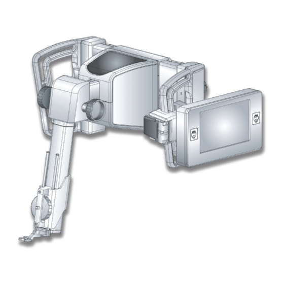
Affirm Instructions for Use Chapter 2—How to Install or Remove the System Installation of Components How to Attach the Biopsy Control Module The Biopsy Control Module attaches to either the left or right handle on the Biopsy Guidance Module. Figure Legend 1. Lock Knob for Articulating Arm 2. Biopsy Control Module Cable 3. Clamp Adjust Knob 4. Attachment Bracket 5. Attachment Bracket Lock Figure 8: Attachment of the Biopsy Control Module 1. Release the Articulating Arm Lock Knob (item 1). 2. -
Page 27: Installation And Removal Of Accessories
Affirm Instructions for Use Chapter 2—How to Install or Remove the System Installation and Removal of Accessories 1.2.1 How to adjust the bracket height 1. Release the Attachment Bracket Lock (item 5). 2. Slide the bracket to the required height. 3. Put the Attachment Bracket Lock (item 5) into the locked position. 1.2.2 How to adjust the Biopsy Control Module position 1. Release the Lock Knob (item 1) for the Articulating Arm. 2. -
Page 28: Biopsy Device Holder
Affirm Instructions for Use Chapter 2—How to Install or Remove the System Installation and Removal of Accessories Biopsy Device Holder To install a biopsy device holder: 1. Align the holes (top and bottom) in the holder with the guide pins on the mount. 2. Align the center hole with the mount screw. 3. Turn the thumbwheel on the mount to attach the device holder. Figure Legend Biopsy Device Holes Mount Screw Thumbwheel To remove a biopsy device holder: 1. Turn the thumbwheel on the mount to release the device holder. 2. Remove the device holder from the mount. Part Number MAN-02866... -
Page 29: Needle Guides
Affirm Instructions for Use Chapter 2—How to Install or Remove the System Installation and Removal of Accessories Needle Guides Always use sterile techniques when you use needle Warning: guides during the patient procedures. To install a disposable Needle Guide: 1. Align the Needle Guide so that the raised‐square side of the Needle Guide fits between the two lobes of the Needle Guide Mount. 2. Slide the open area of the U‐shape in the Needle Guide around the pin in the Needle Guide mount. 3. Push the Needle Guide in until the guide locks into position. Figure Legend Needle Guide Needle Guide Mount Figure 9: How to Install the Needle Guides Note ... -
Page 30: Removal Of Main Components
Affirm Instructions for Use Chapter 2—How to Install or Remove the System Removal of Main Components Removal of Main Components Biopsy Control Module To remove the Biopsy Control Module from the Biopsy Guidance Module: 1. Disconnect the cable of the Biopsy Control Module from the Biopsy Guidance Module. 2. Release the bracket lock. 3. Remove the Biopsy Control Module from the Biopsy Guidance Module. 4. Store the Biopsy Control Module in a protected location. Biopsy Guidance Module To remove the Biopsy Guidance Module from the Selenia Dimensions: 1. Disconnect the Biopsy Guidance Module Cable from the Selenia Dimensions. 2. Hold a handle of the Biopsy Guidance Module with one hand while you release the Locking Levers with the other hand. ... -
Page 31: How To Use The System
Affirm Instructions for Use Chapter 3—How to Use the System System Verifications Chapter 3 How to Use the System System Verifications Confirm the Host Connection When the Selenia Dimensions is On and the Affirm cable connections are correct, the Home screen displays on the Biopsy Control Module. Figure 10: Home Screen on the Biopsy Control Module Perform the QAS Needle Test Perform this test one time each day you plan to use the system to confirm the system accuracy. Record your results in the QAS Needle Test Checklist on page 45. Do not extend the QAS Needle unless the needle is Caution: attached to the Biopsy Guidance Module, and the module is installed on the C‐arm. ... -
Page 32: Figure 11: Admin Screen
Affirm Instructions for Use Chapter 3—How to Use the System System Verifications 1.2.1 Auto Biopsy Mode 1. Select the Admin button on the Selenia Dimensions, then select the QAS button from the Admin screen. Figure 11: Admin Screen 2. When the QAS screen displays on the Selenia Dimensions Acquisition Workstation, select the Biopsy tab. 3. Confirm that QAS appears in the Device field. Figure 12: Device Field in the Biopsy Tab Part Number MAN-02866... - Page 33 Affirm Instructions for Use Chapter 3—How to Use the System System Verifications 4. Remove the Compression Paddle. 5. Attach the QAS Needle at the top end of the Z‐axis Slide Rail, then fully extend the QAS Needle. 6. Press and hold a right or left Motor Enable button pair on the Biopsy Control Module (see Biopsy Control Module Components on page 4). The QAS Needle moves automatically to pre‐programmed X and Y positions. 7. Turn the Z‐axis Control Knob to show 0.0 on the Diff line in all three columns of the Biopsy Control Module. 8. Select the Manual exposure mode, 25kV, 10 mAs, Rhodium filter in the QAS screen. 9. Acquire the stereo images, then Accept the images. The Auto‐Accept feature is not enabled during the QAS procedure. The targeting of the ball at the needle tip occurs automatically. 10. Select the Create Target button to send the target to the Biopsy Control Module. • Verify that the targeting coordinates are within ± 1mm of X, Y, and Z numbers on the Current line of the Biopsy Control Module. If the targeting coordinates are not within ± 1mm, Warning: contact Technical Support. Do not try to adjust the system. Do not perform any biopsy procedure with the Affirm until Technical Support indicates the system is ready for use. ...
- Page 34 Affirm Instructions for Use Chapter 3—How to Use the System System Verifications 1.2.2 Manual Biopsy Mode 1. Perform steps 1 to 8 as stated for the Auto Biopsy Mode on page 16. 2. Press the C‐Arm Stereo Mode button in the Target Guidance screen. Refer to the table in C‐Arm Rotation in the Biopsy Modes on page 28. 3. Rotate the Tube Arm to the first 15° position. 4. Press the x‐ray button and acquire the first 15° image. 5. Rotate the Tube Arm to the opposite 15° position. 6. Press the x‐ray button and acquire the opposite 15° image. 7. Accept the images. The Auto‐Accept feature is not enabled during the QAS procedure. The targeting of the ball at the needle tip occurs automatically. 8. Select the Create Target button to send the target to the Biopsy Control Module. • Verify that the targeting coordinates are within ± 1mm of X, Y, and Z numbers on the Current line of the Biopsy Control Module. • If the targeting coordinates are not within ± 1mm, contact Technical Support. Do ...
-
Page 35: Biopsy Control Module Screens
Affirm Instructions for Use Chapter 3—How to Use the System Biopsy Control Module Screens Biopsy Control Module Screens Home Screen The Home screen displays the name or initials of the user who logs in and any error messages. The Go button takes the user to the Target Guidance screen. Figure 13: The Home Screen Figure Legend User ID Area Go Button Error Message Area Part Number MAN-02866... -
Page 36: Target Guidance Screen
Affirm Instructions for Use Chapter 3—How to Use the System Biopsy Control Module Screens Target Guidance Screen The figure below shows the main screen of the Biopsy Control Module. This screen indicates the current position of the biopsy device, the selected target coordinates and the Cartesian difference between the two positions. The buttons in the Target Guidance screen allow the user to go to the Previous screen (item 3), go to the screen for target selection (item 2), go to the screen for motorized movement of the biopsy device in the X and Y axes (item 1), select the C‐Arm Mode or Stereo Mode for the C‐arm rotation (item 5), and cancel an audible signal (item 7). The display area (item 4) of the Target Guidance screen shows the difference between the current position of the biopsy device and the target coordinates, the status of the system (item 10), the biopsy device installed on the system (item 8), and the safety margins (item 9). (The figure and the figure legend appear on the next page.) Part Number MAN-02866... -
Page 37: Figure 14: Target Guidance Screen
Affirm Instructions for Use Chapter 3—How to Use the System Biopsy Control Module Screens Figure 14: Target Guidance Screen Figure Legend Go to the Jog Mode screen Go to the Select Target screen Go to the Previous screen Target Information Switch between C‐Arm Mode or Stereo Mode (when system is set for Manual Biopsy Mode). This button is gray and disabled. Mute or Enable Sound (An icon displays on this button and an alarm sounds when there is a system fault. See The Sound Button on page 23.) Selected Biopsy Device Safety Margins 10. System Status Note The X, Y, and Z cells in the screen can change color as target coordinates change. See Colored Cells in the Screens on page 22. ... -
Page 38: Figure 15: Green Differential Cells
Affirm Instructions for Use Chapter 3—How to Use the System Biopsy Control Module Screens 2.2.1 Colored Cells in the Screens Green Cells When all Diff cells are green, the biopsy device is in the correct position for the selected target. When the biopsy device is fired, the lesion is at the center of the aperture of the device. Figure 15: Green Differential Cells Yellow and Red Cells Figure 16: Yellow and Red Cells • Yellow indicates the biopsy device is in the correct position for that axis, but you must move the device to the final Z‐position. When the biopsy device is in the final Z‐position, the yellow cell changes to green. • Red indicates a problem with a safety margin. The Sound button appears and the system makes repeated beeps. Make adjustment in the axis indicated by red. When the cell is not red, the device is within the safety limits. Part Number MAN-02866... -
Page 39: Table 3: How To Use The Sound Button
Affirm Instructions for Use Chapter 3—How to Use the System Biopsy Control Module Screens 2.2.2 The Sound Button The Sound button is enabled when there is a system fault. When the Sound button displays, you can control system sounds related to alarms and motor movements of the biopsy device. Table 3: How to Use the Sound Button Sound • When a safety margin is violated, this icon displays and the system repeats a beep sound. • To stop the sound, press the Sound button. All system beep sounds are muted, and the icon on the button changes. • When you correct the safety margin violation, the icon on the button disappears. • Figure 17: Alert Sounds are If you press the button and do not correct the system fault within two minutes, the system beep sounds are enabled Audible ... -
Page 40: Jog Mode Screen
Affirm Instructions for Use Chapter 3—How to Use the System Biopsy Control Module Screens Jog Mode Screen This screen allows the user to manually overwrite the targeting coordinates of the Biopsy Guidance Module. The arrow buttons in the Jog Mode screen change the Jog value of the X and Y coordinates. Other buttons in this screen allow the user to go to the Target Guidance Screen (item 5), and cancel (item 7) an audible signal that sounds when there is a problem with a safety margin. The display area (item 4) of the Jog Mode screen shows the difference between the current position of the biopsy device and the target coordinates, the status of the system (item 10), the biopsy device installed on the system (item 8), and the safety margins (item 9). Red cells indicate a problem with a safety margin. Warning: Patient injury or equipment damage may occur if you continue. Make adjustments to be within safety limits. (The figure and the figure legend appear on the next page.) Part Number MAN-02866... -
Page 41: Figure 19: Jog Mode Screen
Affirm Instructions for Use Chapter 3—How to Use the System Biopsy Control Module Screens Figure 19: Jog Mode Screen Figure Legend Change Y‐axis Jog value in negative direction Change X‐axis Jog value in negative direction Change Y‐axis Jog value in positive direction Target Information Go to the Previous screen Change X‐axis Jog value in positive direction Mute or Enable Sound (An icon displays on this button and an alarm sounds when there is a problem. See The Sound Button on page 23 for more information about the Sound button.) Selected Biopsy Device Safety Margins 10. System Status Part Number MAN-02866... -
Page 42: Select Target Screen
Affirm Instructions for Use Chapter 3—How to Use the System Biopsy Control Module Screens Select Target Screen This screen allows the user to select a different target for biopsy guidance or to move to one of the Home positions. The buttons in the Select Target screen allow the user to go to the Previous screen (item 1), go to the Target screen (item 2), or go to the Left or Right Home Position (item 3 or item 6). The display area (item 4) of the Select Target screen shows one of more sets of target coordinates. The name of the biopsy device that was selected also displays (item 5). To move the biopsy device to one of the targets shown in this screen: 1. Press one of the target coordinates icons or the home buttons. The system changes to the Target Guidance screen. 2. Press and hold a right or left Motor Enable button pair on the Biopsy Control Module. The needle moves to the X and Y positions. Figure 20: Select Target Screen Figure Legend Go to the previous screen Go to the Target Guidance screen Go to the Home Left Position Target Coordinates Biopsy Device ... -
Page 43: Selenia Dimensions
Affirm Instructions for Use Chapter 3—How to Use the System Selenia Dimensions Selenia Dimensions Stereo Views 3.1.1 How to Add a Stereo View 1. From the Procedure screen, select the Add View button. Figure 21: Add a Stereo View Figure Legend Trash icon View Modifier 2. Select the STX tab, then select the view to add and the appropriate View Modifier. 3. Select the Add button. To remove the selected view, select the view then press the Trash icon. Part Number MAN-02866... -
Page 44: Stereo Biopsy Modes
Affirm Instructions for Use Chapter 3—How to Use the System Selenia Dimensions Stereo Biopsy Modes Acquire the stereo images in either the Auto Biopsy Mode or the Manual Biopsy Mode. Make the Biopsy Mode selection at the Acquisition Workstation (refer to How to Select the Biopsy Mode for Image Acquisition on page 30). 3.2.1 C-Arm Rotation in the Biopsy Modes The action of C‐arm rotation for stereotactic image acquisition is different in Auto and Manual Biopsy Modes. Note All C‐Arm movement is disabled when a compression force of 22 Newtons (5 pounds) or greater is applied. In Auto Biopsy Mode In the Auto Biopsy Mode, the Target Guidance screen does not display the C‐Arm Stereo Mode button. In the Auto Biopsy mode, the system automatically allows the C‐arm to move separately from the Tube Arm to acquire the stereo images. When the x‐ray button is pressed to start stereo image acquisition, the Tube Arm automatically moves to the first 15° position, acquires the image, rotates to the opposite 15° position and acquires that image. Note The System Status menu (refer to How to Select the Biopsy ... -
Page 45: Figure 22: Stereo Mode
Affirm Instructions for Use Chapter 3—How to Use the System Selenia Dimensions In Manual Biopsy Mode In Manual Biopsy Mode, the C‐Arm Stereo Mode button displays on the Target Guidance screen. The default setting is Stereo Mode. See the table that follows. Note The C‐Arm Stereo Mode button displays if the system is set for Manual Biopsy Mode. In Auto Biopsy Mode, this button is not displayed. Table 4: The C‐Arm Stereo Mode Button Icon Description of Function • The Tube Arm rotates while the C‐Arm remains in position. • Select Stereo Mode to acquire stereo images (when the system is set for Manual Biopsy Mode). Figure 22: Stereo Mode • The C‐arm and Tube Arm rotate together. • Select C‐Arm Mode to rotate the C‐arm and Tube Arm together to a new patient positioning angle. Figure 23: C‐Arm Mode ... -
Page 46: Figure 24: System Status Icon
Affirm Instructions for Use Chapter 3—How to Use the System Selenia Dimensions 3.2.2 How to Select the Biopsy Mode for Image Acquisition Table 5: How to Select the Biopsy Mode 1. Select the System Status icon. Figure 24: System Status Icon 2. Select System Defaults from the System Status menu. Figure 25: System Status Menu 3. Select the Biopsy tab in the System Defaults screen. 4. Select Auto (or Manual) from the Mode section. Figure 26: System Defaults Screen ... -
Page 47: Biopsy Tab
Affirm Instructions for Use Chapter 3—How to Use the System Selenia Dimensions Biopsy Tab Figure 27: The Biopsy Tab When you select the Biopsy tab, the Biopsy screen appears. This screen displays information about the targets and the biopsy device that is installed on the system. The buttons on the left side of this information allow you to communicate selected targets to the Biopsy Control Module. See Biopsy Staging on page 32 for information about the buttons and data fields on the Biopsy tab screen. Part Number MAN-02866... -
Page 48: Biopsy Staging
Affirm Instructions for Use Chapter 3—How to Use the System Selenia Dimensions Biopsy Staging The buttons on the Biopsy Staging area communicate target information to the Biopsy Control Module. The fields on the right side of the buttons show the selected target and biopsy device. Figure 28: Function Buttons and Data on the Biopsy Tab Figure Legend 1. Create Target sends the current target list that shows in the Biopsy Staging area to the Biopsy Control Module. If the Biopsy Control Module is unplugged after the Caution: targets are transmitted, the Biopsy Control Module deletes the targets. Resend the targets. 2. Reject Target removes the selected target from the list that displays in the Biopsy Staging area, if that target was not created. 3. Resend Target resends the selected target set to the Biopsy Control Module. 4. Project Target shows the selected target on an additional stereo pair on the Preview screen. 5. Delete Target deletes the selected target if that target was created. 6. Move Z‐Target Up moves the final position of the needle away from the Breast Platform and the graphic of the lesion downward. The values for the safety margins ... - Page 49 Affirm Instructions for Use Chapter 3—How to Use the System Selenia Dimensions 7. Move Z‐Target Down moves the final position of the needle toward the Breast Platform and the graphic of the lesion upward. The values for the safety margins change accordingly. 8. Show/Hide Targets shows/hides all targets in the list of targets in the Biopsy Staging area. 9. Device shows the name of the attached biopsy device that was selected from the related drop‐down list. The name, dimensions, and aperture size in the needle for the selected biopsy device display. Patient injury can occur if the device you select in the Warning: Biopsy tab is not the device that is installed on the system. Note If your biopsy device does not show in the drop‐down menu, contact Technical Support. A Service Engineer must enter the device specifications. 10. Targets shows the current target selected from the list of created targets in the drop‐down menu. The active target is the last one created. This target is at the top of the list and displays with an arrow before the coordinates. When multiple targets are created on an image, a target set is created. All targets in the current target set show with an arrow before the coordinates. When you send the target set to the Biopsy Control Module, only the active targets (those with the arrows) transfer and can be selected at the Biopsy Control Module. ...
-
Page 50: Lesion Targeting
Affirm Instructions for Use Chapter 3—How to Use the System Selenia Dimensions Lesion Targeting Note You can use the Zoom tool (in the Tools tab or View Actual Pixels button) to magnify the area of interest in an image. Note If the exam data in the image blocks detection of the lesion, click the Information icon in the Tools tab to hide the data. 1. Select the Accept button to save the stereo images. Note Your service representative can configure the system to Auto‐Accept new images. 2. Click in the center of the lesion in one of the stereo images. 3. Click on the other stereo image, then click in the center of the lesion. 4. Select the Create Target button to save the target. The active target set automatically transfers to the Biopsy Control Module every time a new target is created. 5. Repeat this procedure to create multiple targets (a maximum of six). Note The target that displays on the Target Guidance screen of the Biopsy Control Module is the last target created. The target or target set that shows on the Select Target screen is the last target or target set sent to the Biopsy Control Module. ... -
Page 51: Post Biopsy
Affirm Instructions for Use Chapter 3—How to Use the System Selenia Dimensions Post Biopsy 1. Put in a marker, if desired. 2. Rotate the Z‐axis Control Knob to move the biopsy device away from the breast. 3. Acquire images as necessary. 4. Release compression. Printing Stereo Images When you select a stereo pair from the thumbnail area of the Print screen, the image mode buttons change. See the Selenia Dimensions Instructions for Use for instructions on use of the Print screen. • Select the ‐15 button to show that stereo image in the display area. • Select the +15 button to show that stereo image in the display area. • Select the middle button to make a 2‐up horizontal film with the +15 degree image on top and the ‐15 degree image on the bottom. Figure 29: Stereo Pair Print Screen ... -
Page 53: Care And Cleaning
Affirm Instructions for Use Chapter 4—Care and Cleaning General Information Chapter 4 Care and Cleaning General Information Before each examination, clean and use a disinfectant on any part of the system and any accessory which touches a patient. Preventive Maintenance Schedule Table 6: Radiologic Technologist Preventive Maintenance Schedule Each Maintenance Task Description Daily Semiannually use Clean the Biopsy Paddle with a disinfectant after use.* x Clean the Breast Platform with a disinfectant after use.* x Inspect the Biopsy Paddle for damage before use. x ... -
Page 54: For General Cleaning
Affirm Instructions for Use Chapter 4—Care and Cleaning For General Cleaning For General Cleaning Use a lint‐free cloth or pad and apply a diluted dishwashing liquid. Use the least possible amount of cleaning fluids. The Caution: fluids must not flow or run. If more than soap and water is required, Hologic recommends any one of the following: • 10% chlorine bleach and water with one part commercially available chlorine bleach (normally 5.25% chlorine and 94.75% water) and nine parts water • Commercially available isopropyl alcohol solution (70% isopropyl alcohol by volume, not diluted) • 3% maximum concentration of hydrogen peroxide solution After you apply any of the above solutions, use a pad and apply a diluted dishwashing liquid to clean any parts which touch the patient. If a paddle touches possible infectious materials, Warning: contact your Infection Control Representative for decontamination instructions. To prevent damage to the electronic components, do not ... -
Page 55: To Prevent Possible Injury Or Equipment Damage
Affirm Instructions for Use Chapter 4—Care and Cleaning Geometry Calibration To Prevent Possible Injury or Equipment Damage Do not use a corrosive solvent, abrasive detergent, or polish. Select a cleaning/disinfecting agent that does not damage the plastics, aluminum, or carbon fiber. Do not use strong detergents, abrasive cleaners, high alcohol concentration, or methanol at any concentration. Do not expose equipment parts to steam or high temperature sterilization. Do not let liquids enter the internal parts of the equipment. Do not apply cleaning sprays or liquids to the equipment. Always use a clean cloth and apply the spray or liquid to the cloth. If liquid enters the system, disconnect the electrical supply and examine the system before returning it to use. Wrong cleaning methods can damage the equipment, Caution: decrease imaging performance, or increase the risk of electric shock. Always follow instructions from the manufacturer of the product you use for cleaning. The instructions include the directions and precautions for the application and contact time, storage, wash requirements, protective clothing, shelf life, and disposal. Follow the instructions and use the product in the most safe and effective method. Geometry Calibration Geometry calibration is required semiannually. Perform this calibration using the Geometry phantom supplied with the system. Geometry Calibration Procedure 1. -
Page 57: Troubleshooting
Affirm Instructions for Use Chapter 5—Troubleshooting Audible Alerts Chapter 5 Troubleshooting Audible Alerts Table 7: Affirm Audible Alerts Activity Frequency Duration Repeats? At Power Up: 3 250 ms No Any Needle position within the 1 50 ms Yes safety margin limit: BGM calibrate or configuration operation, Move or Jog: • 3 50 ms No If the operation is prevented • 1 ... - Page 58 Affirm Instructions for Use Chapter 5—Troubleshooting Error Messages Table 8: Affirm Error Messages Error Message How to Correct Comm Error 1. Select the system status icon in the taskbar of the Selenia Dimensions. 2. Select the Clear All Faults options. This error can occur when the manual Z‐control is turned quickly. Hardware Error 1. Select the system status icon in the taskbar of the Selenia Dimensions. 2. Select the Clear All Faults options. 3. If the message continues to display, contact Technical Support. Selftest Error 1. Disconnect the Affirm cable from the Selenia Dimensions. 2. Re‐connect the Affirm to the Selenia Dimensions. 3. If the message continues to display, contact Technical Support. Stuck Switch Fault 1. Disconnect the Biopsy Control Module from the Biopsy Guidance Module. 2. Re‐connect the Biopsy Control Module to the Biopsy Guidance Module. ...
-
Page 59: System Specifications
Affirm Instructions for Use Appendix A—System Specifications Affirm Measurements Appendix A System Specifications Affirm Measurements A. Height 37.1 cm (14.6 inches) B. Width 37.8 cm (14.9 inches) C. Depth 35.6 cm (14 inches) Biopsy Guidance Module Weight 15 pounds Accuracy ± 1 mm Range of Movement X‐axis: ±35 mm Y‐axis: +72.8 mm Z‐axis: + 161 mm Speed of Motorized Movements Continuous: No faster than 5 mm per second) Incremental: 0.5 mm steps Power System Input from Selenia Dimensions: +15Vdc±10% and +5Vdc±10% ... -
Page 61: Forms
Affirm Instructions for Use Appendix B—Forms QAS Needle Test Checklist Appendix B Forms QAS Needle Test Checklist Date Tech X Error Y Error Z Error Pass/Fail ... -
Page 63: Index
Affirm Instructions for Use Index Index G general information • 1 A glossary • xiii adjustment H biopsy control module position • 11 Hologic technical support • 37 bracket height • 11 home screen • 19 control module position • 11 host connection verification • 15 attachment biopsy control module • 10 I biopsy holder • 12 needle guides • 13 information auto biopsy mode • 28 general • 1 installation B biopsy control module • 10 biopsy device holder • 12 biopsy control module • 1, 4 biopsy guidance module • 9 biopsy device needle guides • 13 holder, attachment • 12 intended use • xi biopsy geometry calibration • 39 biopsy guidance module • 1 M biopsy modes • 28 ... - Page 64 Affirm Instructions for Use Index requirements training • xii S select target screen • 26 Selenia Dimensions biopsy tab • 31 skills needed • xii specifications • 43 stereo biopsy mode auto • 28 C‐arm rotation • 28 manual • 28 selection • 30 stereo views • 27 system description • 1 host connection verification • 15 specifications • 43 verification • 15 T target guidance screen • 20 target lesion • 34 technical support • xiii terms and definitions • xiii training requirements • xii Part Number MAN-02866...
Need help?
Do you have a question about the Affirm MAN-02866 and is the answer not in the manual?
Questions and answers