Table of Contents
Advertisement
Quick Links
Advertisement
Table of Contents
Troubleshooting

Related Manuals for Hologic Brevera


Summary of Contents for Hologic Brevera
- Page 3 Brevera ® Breast Biopsy System User Guide Models BREV100, BREV200 Part Number MAN-04303-002 Revision 006 May 2019...
- Page 4 Email: BreastHealth.Support@hologic.com © 2018 - 2019 Hologic, Inc. Printed in the USA. This manual was originally written in English. Hologic, Brevera, CorLumina, ATEC, Eviva, and associated logos are trademarks and/or registered trademarks of Hologic, Inc., and/or its subsidiaries in the United States and/or other countries. All other trademarks, registered trademarks, and product names are the property of their respective owners.
-
Page 5: Table Of Contents
Brevera Breast Biopsy System User Guide Table of Contents Table of Contents List of Figures _________________________________________________________________ xi List of Tables _________________________________________________________________xiii 1: Introduction __________________________________________________________________1 Preface ..................................1 Indications for Use ..............................1 Contraindications ..............................1 Essential Performance ............................1 System Capabilities ..............................2 User Profiles................................ - Page 6 Brevera Breast Biopsy System User Guide Table of Contents System Connections .............................. 31 3.2.1 Power and Network Connections ......................32 3.2.2 Footswitch Connection .......................... 33 3.2.3 Device Driver and Remote Control Connections ................33 3.2.4 Suction Canister Connections ....................... 34 3.2.5...
- Page 7 Brevera Breast Biopsy System User Guide Table of Contents 6: Imaging System Modes _______________________________________________________65 X-ray Mode ................................65 No X-ray Mode ..............................65 Single Chamber Mode ............................66 7: Biopsy ______________________________________________________________________69 Set Up the System ..............................69 Connect the Device Driver and the Biopsy Supplies ..................69 Pre-Procedure System Check ..........................
- Page 8 Brevera Breast Biopsy System User Guide Table of Contents 10.2 Component Specific Cleaning and Disinfection ..................... 100 10.2.1 How to Clean and Disinfect the Console Exterior Surfaces ............100 10.2.2 How to Clean and Disinfect the Device Driver and Remote Control ..........101 10.2.3...
- Page 9 Brevera Breast Biopsy System User Guide Table of Contents Appendix C: Brevera Compatible Components and Accessories ____________________123 Hologic Factory-Verified Compatible Components and Accessories ............123 Appendix D: Owner’s Record ___________________________________________________125 Brevera Breast Biopsy System with CorLumina Imaging Technology ............125 Index ________________________________________________________________________127 MAN-04303-002 Revision 006...
-
Page 11: List Of Figures
Brevera Breast Biopsy System User Guide Table of Contents List of Figures Figure 1: Brevera Breast Biopsy System Overview ....................... 7 Figure 2: Label Locations ..............................19 Figure 3: System Components (Front, Right) ....................... 21 Figure 4: System Components (Back, Left) ........................22 Figure 5: Imaging Cabinet Components ........................ - Page 12 Figure 60: Filter Info and Comments Screens ......................93 Figure 61: Admin Screen ..............................95 Figure 62: System Tools Button ............................97 Figure 63: The System Tools Screen ..........................98 Figure 64: Brevera System Measurements ........................109 MAN-04303-002 Revision 006...
-
Page 13: List Of Tables
Brevera Breast Biopsy System User Guide Table of Contents List of Tables Table 1: The Filter Criteria Options ..........................49 Table 2: Admin Screen Functions ..........................96 Table 3: The System Tools .............................. 98 Table 4: Recommended Maintenance Schedule for the User ................... 107 Table 5: Service Engineer Preventive Maintenance .................... -
Page 15: 1: Introduction
Essential Performance The essential performance of the Brevera breast biopsy system is to maintain compliance with IEC 61010-2-91:2012 to prevent exposure of the patient, operator, or other individuals to unacceptable levels of X-ray radiation. -
Page 16: System Capabilities
NOT intended to be used outside the standards, specifications, and limitations outlined in these instructions for use. The Brevera biopsy needle is single-use and is disposable. The user connects the biopsy needle to a reusable device driver and connects the biopsy device components to the console. -
Page 17: User Profiles
Understands how to operate a computer and its peripherals. Where to Find the Installation Instructions Contact Hologic Technical Support for installation instructions. Where to Find Technical Description Information Contact Hologic Technical Support for technical description information. MAN-04303-002 Revision 006 Page 3... -
Page 18: Warranty Statement
1.11 Product Complaints Report any complaints or problems in the quality, reliability, safety, or performance of this product to Hologic. If the device has caused or added to patient injury, immediately report the incident to Hologic. 1.12 Hologic Cybersecurity Statement Hologic continuously tests the current state of computer and network security to examine possible security problems. -
Page 19: Where To Obtain Copies Of The Manuals
Chapter 1: Introduction 1.13 Where to Obtain Copies of the Manuals To obtain a PDF file of the User Guide, go to the support pages at www.Hologic.com. • Adobe Acrobat Reader version 5.0 or higher is required to view the PDF file. -
Page 21: 2: General Information
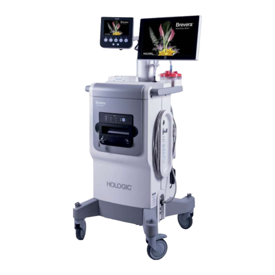
Chapter 2 General Information System Overview The Brevera breast biopsy system with CorLumina imaging technology has system components for vacuum-assisted breast tissue biopsy and system components for x-ray generation and image acquisition. The user interface for data entry, patient selection, and image acquisition and review is on the Imaging display. -
Page 22: Safety Information
WARNING! Portable and mobile RF communications equipment can affect the Brevera breast biopsy system. Do not use portable RF communications equipment any closer than 30 cm (12 inches) to any part of the Brevera system, including cables. WARNING! The Brevera breast biopsy system console is designed to use the power cord provided. - Page 23 To prevent fire or shock hazard, do not expose the console to rain or moisture. WARNING! Only trained Service Engineers authorized through Hologic can open any of the panels. This system contains lethal voltages. WARNING! Electrical equipment used near flammable anesthetics can cause an explosion.
- Page 24 Dispose of all opened disposable instruments whether used or not. WARNING! Do not resterilize or reuse the Brevera biopsy needle or the introducer. Resterilization or reuse can compromise the integrity of the instrument. This can lead to potential risks of failure of the biopsy needle to perform as intended or to cross-contamination associated with using inadequately cleaned and sterilized devices.
- Page 25 Warning: The Brevera biopsy device should only be used by physicians trained in percutaneous biopsy procedures. Warning: Use sound professional judgment when using the Brevera breast biopsy device on patients with breast implants.
- Page 26 Brevera Breast Biopsy System User Guide Chapter 2: General Information Warning: Cables and cords can pose a tripping hazard. Position cords safely out of the way. When not in use, wind cords securely around the cord management plates. Caution: If the console will not be used for several days or an extended period of time, disconnect the console from the electrical outlet.
- Page 27 Caution: If you are a Hologic customer in the United States, contact Hologic if you cannot correct a problem using these instructions for use. Outside of the United States, contact your distributor or local Hologic representative with questions, comments, or technical service issues.
-
Page 28: Interlocks
To make another exposure: 1. Select the OK button in the system message dialog box. 2. Select the status icon (shaped like the Brevera breast biopsy console) in the taskbar at the bottom of the Imaging display screen. -
Page 29: Compliance Statements
If adjacent or stacked use is necessary, make sure that the ME Equipment or ME System operates correctly in this configuration. Caution: Changes or modifications not expressly approved by Hologic could void your authority to operate the equipment. 2.5.2... -
Page 30: Symbols
Brevera Breast Biopsy System User Guide Chapter 2: General Information Symbols This section describes the Symbols on this system. Symbol Description "ON" and "OFF" (power) Alternating current (AC) Atmospheric pressure limitation Authorized representative in the European Community Batch code Catalog number... - Page 31 Brevera Breast Biopsy System User Guide Chapter 2: General Information Symbol Description Do not re-use Do not stack above ‘n’ high Contains or presence of phthalate Do not use if package is damaged European Community Waste Electrical and Electronic Equipment...
- Page 32 Brevera Breast Biopsy System User Guide Chapter 2: General Information Symbol Description Saline tubing management plate Serial Number Sterilized using irradiation Temperature limit The equipment or accessory is suitable for continuous immersion in IPX8 water (up to 1 m of submersion for 1 hour).
-
Page 33: Label Locations
Brevera Breast Biopsy System User Guide Chapter 2: General Information Label Locations Figure 2: Label Locations MAN-04303-002 Revision 006 Page 19... -
Page 35: 3: Components, Controls, And Indicators
Brevera Breast Biopsy System User Guide Chapter 3: Components, Controls, and Indicators Chapter 3 Components, Controls, and Indicators System Components Figure 3: System Components (Front, Right) MAN-04303-002 Revision 006 Page 21... -
Page 36: Figure 4: System Components (Back, Left)
Brevera Breast Biopsy System User Guide Chapter 3: Components, Controls, and Indicators Figure 4: System Components (Back, Left) Page 22 MAN-04303-002 Revision 006... - Page 37 Brevera Breast Biopsy System User Guide Chapter 3: Components, Controls, and Indicators Figure Legend Tissue filter drawer The compartment where biopsy cores are collected and imaged. Imaging panel Includes status indicators and lockout key for the x-ray system. Console tray Storage and staging area for the biopsy needle packaging.
- Page 38 Brevera Breast Biopsy System User Guide Chapter 3: Components, Controls, and Indicators Figure Legend 21 Imaging display height- Depressing the pedal releases the Imaging display mounting slide to allow adjust pedal for height adjustment. Release the pedal to lock the slide.
-
Page 39: Imaging Cabinet Components
3.1.1 Imaging Cabinet Components The Brevera console houses a cabinet where the biopsy cores are collected and imaged. The cores are collected in a disposable tissue filter that is placed in the drawer of the imaging cabinet. The imaging cabinet includes a panel that gives status information about the x-ray system. -
Page 40: Suction Canister Components
Brevera Breast Biopsy System User Guide Chapter 3: Components, Controls, and Indicators 3.1.2 Suction Canister Components Figure Legend 1. "Patient" port – receives the suction tubing (clear with a blue connector end) from the tissue filter 2. Cap for patient port 3. -
Page 41: Biopsy Device Components
3.1.3 Biopsy Device Components The Brevera breast biopsy device consists of a sterile, disposable biopsy needle that locks into the non-sterile, Brevera reusable device driver. The biopsy needle includes a tissue filter assembly to collect the biopsy cores for imaging. -
Page 42: Figure 9: Biopsy Needle Components
Brevera Breast Biopsy System User Guide Chapter 3: Components, Controls, and Indicators Biopsy Needle Components The biopsy needle includes the disposable needle itself and the tubing for the vacuum and saline lines. The biopsy needle also includes a tissue filter assembly to collect the biopsy cores for imaging. -
Page 43: Figure 10: Biopsy Needle Components - Detailed
Brevera Breast Biopsy System User Guide Chapter 3: Components, Controls, and Indicators Figure 10: Biopsy Needle Components - Detailed Figure Legend 1. Trocar tip 8. Thumbwheel 2. Outer cannula aperture 9. Button for engaging and disengaging the biopsy needle and device driver (both sides) 3. -
Page 44: Figure 11: Tissue Filter Components
Brevera Breast Biopsy System User Guide Chapter 3: Components, Controls, and Indicators Tissue Filter Components The tissue filter is a twelve-chambered container where the biopsy cores are collected for imaging. During the biopsy process, the tissue samples are aspirated through the biopsy needle tubing to the in-line tissue filter. -
Page 45: System Connections
Chapter 3: Components, Controls, and Indicators System Connections This section provides information on how to make all of the necessary connections to set up the Brevera breast biopsy system for use. The following connections will be explained: 1. Power and network connections 2. Footswitch connection 3. -
Page 46: Power And Network Connections
"hospital grade". Check grounding continuity regularly. 3.2.1 Power and Network Connections 1. Put the Brevera breast biopsy system in a location where you can easily access power connections and network connections. 2. Connect the system AC power cord to the electrical outlet. -
Page 47: Footswitch Connection
Brevera Breast Biopsy System User Guide Chapter 3: Components, Controls, and Indicators 3.2.2 Footswitch Connection Warning: Position the footswitch and power cords to prevent accidental tripping. Warning: Position the footswitch to prevent accidental operation by a patient or wheelchair. The footswitch is initially installed by a Service Engineer. If the footswitch is disconnected from the console, insert the footswitch cord into the footswitch receptacle (on the back of the console). -
Page 48: Suction Canister Connections
Brevera Breast Biopsy System User Guide Chapter 3: Components, Controls, and Indicators 3.2.4 Suction Canister Connections The system will generate vacuum when the proper modes are selected. The vacuum connections require a suction canister. The suction canister connects to the suction tubing from the tissue filter and to the tubing of the vacuum line assembly. -
Page 49: Figure 15: Biopsy Needle And Device Driver Connection
Brevera Breast Biopsy System User Guide Chapter 3: Components, Controls, and Indicators The biopsy needle is packaged with the suction and saline tubing, the tissue filter, and the introducer. The biopsy needle is already connected to the suction and saline lines. -
Page 50: Figure 16: Tissue Filter Connections In The Tissue Filter Drawer
Note Each Brevera disposable biopsy needle package includes a tissue filter cap. Save the tissue filter cap until the biopsy acquisition is complete. The tissue filter cap covers the tissue filter when the biopsy cores are placed in formalin. -
Page 51: Controls And Indicators
Brevera Breast Biopsy System User Guide Chapter 3: Components, Controls, and Indicators Controls and Indicators 3.3.1 Imaging Panel Controls and Indicators Figure 18: Imaging Panel Controls and Indicators Figure Legend 1. Status indicators Drawer Closed = LED is green when the tissue filter drawer is fully closed. -
Page 52: Mode Controls And Biopsy Device Arm And Fire Controls
Brevera Breast Biopsy System User Guide Chapter 3: Components, Controls, and Indicators 3.3.2 Mode Controls and Biopsy Device Arm and Fire Controls Figure 19: Mode, Arm and Fire Buttons Figure Legend System status At the top of the Technologist display screen, four tabs indicate the x-ray status, the needle position, the aperture size, and the vacuum status. -
Page 53: How To Lock And Unlock A Caster
Brevera Breast Biopsy System User Guide Chapter 3: Components, Controls, and Indicators Figure Legend 11. Arm button This push-button control retracts the outer cannula on the biopsy needle. The user must press and hold the Arm button to arm the needle. -
Page 54: How To Start The System
Brevera Breast Biopsy System User Guide Chapter 3: Components, Controls, and Indicators How to Start the System Warning: Do not place fingers on the metal parts of the device driver. These parts can move when the system powers on. Note The console beeps three times before resetting the position of the metal parts of the device driver. -
Page 55: Log In
Brevera Breast Biopsy System User Guide Chapter 3: Components, Controls, and Indicators 3.6.1 Log In The Select an Operator screen shows user names or user groups (such as the Manager group). If your user name or group is not shown, select the Show All button. -
Page 57: 4: User Interface - Imaging Display
Brevera Breast Biopsy System User Guide Chapter 4: User Interface - Imaging Display Chapter 4 User Interface - Imaging Display About the Taskbar The taskbar at the bottom of the screen displays additional icons. For some of the icons, you can select the icon to access information or perform system tasks. -
Page 58: The Select Patient Screen
Brevera Breast Biopsy System User Guide Chapter 4: User Interface - Imaging Display Figure Legend System Status Icons If the yellow exclamation mark icon is displayed and this taskbar section flashes yellow, select the icon for more information about the error. -
Page 59: How To Change The Language
Brevera Breast Biopsy System User Guide Chapter 4: User Interface - Imaging Display Figure Legend 1. Quick Search the local database for the Patient Name, Patient ID, or Accession Number. Search Two tabs display at the top of the screen. These tabs are configurable. A Manager 2. -
Page 60: How To Add A Patient
Brevera Breast Biopsy System User Guide Chapter 4: User Interface - Imaging Display 4.2.3 How to Add a Patient 1. In the Select Patient screen, select the New button. 2. Type in new patient information (fields with an asterisk are required). Use the arrows to access the next or previous screen. -
Page 61: How To Edit The Patient Information
Brevera Breast Biopsy System User Guide Chapter 4: User Interface - Imaging Display 4.2.4 How to Edit the Patient Information 1. In the Select Patient screen, select the patient name, then select the Edit button. 2. In the Edit Patient screens, make the changes. Use the arrows to access the next or previous screen. -
Page 62: How To Delete A Patient
Brevera Breast Biopsy System User Guide Chapter 4: User Interface - Imaging Display 4.2.5 How to Delete a Patient 1. In the Select Patient screen, select one or more patients. 2. Select the Delete button. 3. To the Confirmation Required prompt, select Yes. -
Page 63: Table 1: The Filter Criteria Options
Brevera Breast Biopsy System User Guide Chapter 4: User Interface - Imaging Display The Filter Criteria and Columns Tabs in the Patient Filter Screen The Filter Criteria tab allows you to change the filtering options for the patient list. When you select or deselect an option, the change shows in the results area of the screen. -
Page 64: How To Refresh The Worklist
Brevera Breast Biopsy System User Guide Chapter 4: User Interface - Imaging Display 4.2.7 How to Refresh the Worklist Select the Refresh Worklist button to update the patient lists. 4.2.8 How to Query the Worklist Use the Query Worklist feature to search for a patient or a list of patients. Use one or more fields to query the Modality Worklist Provider. - Page 65 Brevera Breast Biopsy System User Guide Chapter 4: User Interface - Imaging Display Figure Legend Patient information Shows the patient name and ID. Image Real-time image of the specimen in the tissue filter. The letter-designation on the tissue filter chamber is visible in the image.
-
Page 66: How To Select A Procedure
Brevera Breast Biopsy System User Guide Chapter 4: User Interface - Imaging Display 4.3.1 How to Select a Procedure Select an entry from the list in the Procedure information area of the screen. 4.3.2 How to Add a Procedure 1. To add another procedure for the active patient, select the + button in the upper right of the Procedure screen to display the Add Procedure dialog box. -
Page 67: How To Access The Reimage Feature
Brevera Breast Biopsy System User Guide Chapter 4: User Interface - Imaging Display 4.3.6 How to Access the Reimage Feature Select the Reimage button to acquire a new image of a specimen already in the tissue filter chambers. Refer to How to Reimage on page 94 for more information. -
Page 68: How To Use The On-Demand Outputs
Brevera Breast Biopsy System User Guide Chapter 4: User Interface - Imaging Display 4.4.3 How to Use the On-Demand Outputs The On-Demand Outputs are: Archive, Export, or Print. You can manually Archive, Export, or Print an image until the patient is closed. -
Page 69: Figure 30: Example, Two Images Selected For Archive/Export
Brevera Breast Biopsy System User Guide Chapter 4: User Interface - Imaging Display How to Archive The archive function sends data to a PACS device. 1. Select the Archive/Export button. The images from the current procedure appear in the main window. -
Page 70: Figure 31: Example Of The Print Screen
Brevera Breast Biopsy System User Guide Chapter 4: User Interface - Imaging Display How to Print Figure 31: Example of the Print Screen Figure Legend Film format Select one, two, or six images per film (number of tiles per film). A green rectangle indicates the position that the active image will have on the film. - Page 71 Brevera Breast Biopsy System User Guide Chapter 4: User Interface - Imaging Display Image thumbnails Choose the images to output by touching the image thumbnail. The selected image thumbnail is surrounded by a green box in the thumbnail area and the position of that image appears as a green box in the film format area.
-
Page 72: How To Do The Gain Calibration
Brevera Breast Biopsy System User Guide Chapter 4: User Interface - Imaging Display 4.4.4 How to Do the Gain Calibration Do the Gain Calibration monthly and when artifacts are seen. Note When the system shows the Gain Calibration message, do the calibration before you proceed with using the system. -
Page 73: 5: User Interface - Technologist Display
Standby, Test, Biopsy, Lavage, and Aspirate. Technologist Display Screens and Modes When the Brevera breast biopsy system powers on, it requires setup and a test cycle. Setup and testing are completed by following the prompts on the Technologist display. Setup After powering on the system, the Setup screen appears on the Technologist display. -
Page 74: Figure 33: Test Screen
Brevera Breast Biopsy System User Guide Chapter 5: User Interface - Technologist Display Test After setup is successful, the system requires testing. The device driver, biopsy needle, and tissue filter must be connected and installed to run Test mode. It is not necessary for the X-ray system to be ready to run Test mode. -
Page 75: Figure 34: Test Screen - Arm And Fire
Brevera Breast Biopsy System User Guide Chapter 5: User Interface - Technologist Display Figure 34: Test Screen - Arm and Fire Standby When the system is in Standby mode, the vacuum is off and, if a biopsy device is connected, the aperture on the needle is closed. The system cannot arm or fire the biopsy needle when it is in Standby mode. -
Page 76: Figure 36: Biopsy Screen
Brevera Breast Biopsy System User Guide Chapter 5: User Interface - Technologist Display Biopsy When the system is in Biopsy mode, depressing the footswitch activates the vacuum and operation of the biopsy device. In Biopsy mode, the biopsy device can be armed and fired with the remote control. -
Page 77: Figure 37: Lavage Screen
Brevera Breast Biopsy System User Guide Chapter 5: User Interface - Technologist Display Lavage When the system is in Lavage mode, the vacuum system is activated and will pull saline through the system. The aperture on the needle is open during Lavage mode. Depressing the footswitch does not control the flow of saline in Lavage mode. -
Page 78: Figure 38: Aspirate Screen
Brevera Breast Biopsy System User Guide Chapter 5: User Interface - Technologist Display Aspirate When the system is in Aspirate mode, the vacuum system is continuously on and the aperture on the needle is open. Aspirate mode allows for continuous vacuum to aspirate the biopsy cavity. -
Page 79: 6: Imaging System Modes
Brevera Breast Biopsy System User Guide Chapter 6: Imaging System Modes Chapter 6 Imaging System Modes X-ray Mode X-ray mode is the default mode of the Imaging system. To use the X-ray mode, start up the system and log in. Make sure the key switch on the imaging panel is in the unlocked position. -
Page 80: Single Chamber Mode
Brevera Breast Biopsy System User Guide Chapter 6: Imaging System Modes Single Chamber Mode The system has a specialized mode that enables the user to perform a biopsy without taking any images when the Imaging system cannot detect or index the tissue filter. The Single Chamber tissue filter does not move or change position during the biopsy acquisition cycle. -
Page 81: Figure 41: Prompt For The Single Chamber Tissue Filter
Brevera Breast Biopsy System User Guide Chapter 6: Imaging System Modes Figure 42: Single Chamber Tissue Filter Figure 41: Prompt for the Single Chamber Tissue Filter The Imaging display does not show the usual user interface screens. In place of the x-ray image, the Imaging display shows a real-time video of the tissue filter. -
Page 83: 7: Biopsy
Brevera Breast Biopsy System User Guide Chapter 7: Biopsy Chapter 7 Biopsy Set Up the System 1. Move the console into position and lock the casters. 2. Make sure the footswitch is connected. 3. Connect the console to power. 4. Connect the network cable to the Ethernet port (optional). - Page 84 Brevera Breast Biopsy System User Guide Chapter 7: Biopsy Device Driver Warning: Do not place fingers on the metal parts of the device driver. These parts can move before a biopsy needle is installed. 1. Slide the device driver onto the device driver holder on the console until it clicks.
- Page 85 Brevera Breast Biopsy System User Guide Chapter 7: Biopsy 4. Hold the biopsy needle in one hand, with the gears facing down and the sheathed needle tip facing to the right. Line up the tab on the biopsy needle with the notch in the device driver.
- Page 86 Brevera Breast Biopsy System User Guide Chapter 7: Biopsy 7. Get a saline bag and remove the protective cap. (A 250 cc saline bag is recommended.) 8. Remove the saline tubing from the biopsy needle packaging. 9. Insert the spike into the saline bag.
- Page 87 Figure 46: Seat the Tissue Filter in the Tissue Filter Drawer Note Each Brevera disposable biopsy needle includes a tissue filter cap. Save the tissue filter cap until the biopsy acquisition is complete. The tissue filter cap covers the tissue filter when the biopsy cores are placed in formalin.
- Page 88 Brevera Breast Biopsy System User Guide Chapter 7: Biopsy 5. Feed the gray tubing through the guide on the left side and feed the clear tubing through the guide on the right side of the drawer so that the drawer is able to close.
-
Page 89: Pre-Procedure System Check
1. With the console in the desired location and powered on, the default mode is Standby. In Standby mode, the green LED indicator flashes above the Test button. 2. Assemble the Brevera breast biopsy device. Refer to Connect the Device Driver and the Biopsy Supplies on page 69 for information on assembling the biopsy device. -
Page 90: Prepare For Image Acquisition
Brevera Breast Biopsy System User Guide Chapter 7: Biopsy Prepare for Image Acquisition Refer to The Select Patient Screen on page 44 for detailed information on the screen components. 1. Select a patient from the worklist in the Select Patient screen, or manually add a new... -
Page 91: Attach The Introducer To The Biopsy Device
Brevera Breast Biopsy System User Guide Chapter 7: Biopsy Attach the Introducer to the Biopsy Device 1. With the system in Standby mode, remove the protective sheath from the biopsy needle. 2. Carefully slide the introducer over the needle of the biopsy device. Advance the hub of the introducer up to the device driver. -
Page 92: Attach A Biopsy Device Adapter To The Biopsy Guidance System
3. Align the biopsy device with the biopsy device adapter. 4. Slide the biopsy device forward until the introducer on the distal end of the Brevera breast biopsy device engages with the biopsy device adapter and the release latch of the driver engages with the proximal end of the biopsy device adapter. -
Page 93: Performing A Biopsy And Acquiring Real-Time Images
Brevera Breast Biopsy System User Guide Chapter 7: Biopsy Performing a Biopsy and Acquiring Real-time Images Perform all steps per standard interventional technique. 1. Identify the targeted area and prepare the site as required. 2. Assemble the biopsy device and advance it to the desired coordinates provided by the imaging system. - Page 94 Brevera Breast Biopsy System User Guide Chapter 7: Biopsy 6. Begin tissue acquisition. Press down on the footswitch and hold it in the depressed position throughout the biopsy procedure. • Removing your foot from the footswitch will inactivate or stop the device after completing the current cycle and the x-ray for the core in that cutting cycle.
-
Page 95: When The Twelve Chambers Of The Tissue Filter Contain Cores
The specimen jar should have a minimum inner diameter of 6.1 cm (2.4 inches) and a minimum height of 5.7 cm (2.25 inches) in order to fit a Brevera tissue filter. 7. Slowly submerge the tissue filter to allow the formalin to enter the chambers and air to escape. -
Page 96: Lavage And Aspirate
Brevera Breast Biopsy System User Guide Chapter 7: Biopsy 7.8.2 Lavage and Aspirate Lavage Select Lavage mode to irrigate the cavity and to clear the biopsy device of tissue. The system will turn the vacuum on, open the aperture, open the saline pinch valve, and close the aspiration valve in order to push saline through the aperture. -
Page 97: Deploying A Biopsy Site Marker
Brevera Breast Biopsy System User Guide Chapter 7: Biopsy 7.8.4 Deploying a Biopsy Site Marker To deploy a biopsy site marker, refer to the biopsy site marker instructions for use. Note Make sure that the correct biopsy marker is selected for the needle length used. -
Page 98: Conclude The Procedure
The specimen jar should have a minimum inner diameter of 6.1 cm (2.4 inches) and a minimum height of 5.7 cm (2.25 inches) in order to fit a Brevera tissue filter. 7. Slowly submerge the tissue filter to allow the formalin to enter the chambers and air to escape. -
Page 99: How To Change The Biopsy Needle Between Procedures
Brevera Breast Biopsy System User Guide Chapter 7: Biopsy 7.10 How to Change the Biopsy Needle Between Procedures Follow these instructions to change the biopsy needle for a new procedure. 1. Confirm that the console is in Standby mode. 2. Press the buttons on the sides of the biopsy needle to disengage it from the device driver. -
Page 100: How To Change The Biopsy Needle During Troubleshooting
Brevera Breast Biopsy System User Guide Chapter 7: Biopsy 7.11 How to Change the Biopsy Needle During Troubleshooting Follow these instructions to change the biopsy needle to troubleshoot issues during setup and testing. 1. Slide the device driver onto the device driver holder on the console until it clicks. - Page 101 Brevera Breast Biopsy System User Guide Chapter 7: Biopsy 5. Wait for the device driver to home. 6. Install the new biopsy supplies and the new biopsy needle. Refer to Connect the Device Driver and the Biopsy Supplies on page 69 for detailed instructions.
-
Page 103: 8: The Images
Brevera Breast Biopsy System User Guide Chapter 8: The Images Chapter 8 The Images Introduction After you make an exposure, the acquired image displays and is accepted automatically. A thumbnail image appears on the screen, with the corresponding letter designation for the tissue filter chamber. -
Page 104: How To Tag An Image
Brevera Breast Biopsy System User Guide Chapter 8: The Images 8.2.1 How to Tag an Image The Tag tool is the round button in the upper right corner of the image. Pressing this button selects or deselects the active image. Tagged images show a green check mark in the upper right of the image and the image thumbnail. -
Page 105: The Review Mode Screen
Brevera Breast Biopsy System User Guide Chapter 8: The Images 8.2.2 The Review Mode Screen The Review Mode screen allows for a quick review of the images. The Review Mode screen no longer shows an active image and instead shows larger thumbnails of the images. The images can be quickly tagged by selecting them from the group of images instead of tagging them individually from the Procedure screen. -
Page 106: Image Enhancement Tools
Brevera Breast Biopsy System User Guide Chapter 8: The Images 8.2.3 Image Enhancement Tools When you select the Tools button, the Image Enhancement Tools bar displays on the active image. Select the tool icon to enable it. The active tool appears to be pressed into the tools bar. -
Page 107: The Filter Info And Comments Screen
Brevera Breast Biopsy System User Guide Chapter 8: The Images 8.2.4 The Filter Info and Comments Screen From the Procedure screen, click on the Filter Info button to make notes or comments about image content. One set of comments can be added per tissue filter. Comments are saved with the images from that tissue filter and are exported with the image or images. -
Page 108: How To Reimage
Brevera Breast Biopsy System User Guide Chapter 8: The Images Figure Legend 1. Scroll between the two screens using the arrows. 2. Use the on-screen keyboard to type, edit, and remove Filter Comments. 3. The Procedure Info is the information already in the system for the procedure. It cannot be edited on the Filter Info and Comments screen. -
Page 109: 9: System Administration Interface
The figures in this User Guide show the Admin screen with Manager level access. A Radiological Tech (Primary User) has access to some functions on the Admin screen. A Manager system user has access to more functions on the Admin screen. A Hologic Service User has access to all functions on the Admin screen. -
Page 110: Table 2: Admin Screen Functions
Brevera Breast Biopsy System User Guide Chapter 9: System Administration Interface Table 2: Admin Screen Functions Section Screen Function System System Tools The interface for service for the configuration of and identification of problems. System Diagnostics Shows the status of all subsystems including the x-ray detector and the camera above the tissue filter drawer. -
Page 111: How To Use The System Tools
Brevera Breast Biopsy System User Guide Chapter 9: System Administration Interface How to Use the System Tools The Managers (and Hologic Service) can access the System Tools function. This function contains the configuration information about the system. To access the System Tools function: 1. -
Page 112: The System Tools Screen
Brevera Breast Biopsy System User Guide Chapter 9: System Administration Interface 9.2.1 The System Tools Screen Figure 63: The System Tools Screen Table 3: The System Tools Section Description Getting Started About The introduction to the service tool. List of common questions. -
Page 113: 10: Maintenance, Cleaning, And Disinfecting
Apply disinfecting solutions to the system using a clean, lint-free cloth or wipe. Wipe the system with the wet cloth, observing appropriate contact (wet) times. Do not spray cleaning solutions directly on the console or other parts of the Brevera breast biopsy system. -
Page 114: 10.1.3 To Prevent Possible Injury Or Equipment Damage
Brevera Breast Biopsy System User Guide Chapter 10: Maintenance, Cleaning, and Disinfecting 10.1.3 To Prevent Possible Injury or Equipment Damage Do not use a corrosive solvent, abrasive detergent, or polish. Select a cleaning/disinfecting agent that does not damage the plastics, aluminum, or carbon fiber. -
Page 115: 10.2.2 How To Clean And Disinfect The Device Driver And Remote Control
• Do not spray cleaning or disinfectant solutions directly on the reusable device driver, the remote control, or other parts of the Brevera breast biopsy system. • Do not immerse the reusable device driver in liquid. 10.2.3 How to Clean and Disinfect the Tissue Filter Drawer •... -
Page 116: 10.2.5 How To Clean The Technologist Display
Brevera Breast Biopsy System User Guide Chapter 10: Maintenance, Cleaning, and Disinfecting Note There are many commercially available products to clean LCD displays. Any product that is free of the ingredients or abrasives described above and used according to the directions of the manufacturer can be safely used. -
Page 117: 10.2.6 How To Clean The Footswitch
Brevera Breast Biopsy System User Guide Chapter 10: Maintenance, Cleaning, and Disinfecting 10.2.6 How to Clean the Footswitch WARNING! Do not immerse the footswitch in water. Immersion in water will cause damage and may cause electrical shock or death. 1. Disconnect the footswitch from the console. -
Page 118: Preventive Maintenance
Every twelve months, the preventive maintenance service is to be performed only by Hologic Technical Services or a Hologic-certified technician. Contact Hologic Technical Support or your local Hologic representative for more information on preventive maintenance and biomedical training. 10.3.1 Vacuum Line Assembly How to Inspect the Vacuum Line Assembly 1. -
Page 119: 10.3.2 Device Driver
10. Follow the prompts on the Technologist display until testing is complete. 11. When testing is successful, the system goes into Standby mode. 12. Power off the system if desired. 13. Contact your local Hologic representative for product return instructions. MAN-04303-002 Revision 006 Page 105... -
Page 120: 10.3.3 Footswitch
How to Inspect the Power Cord 1. Once every quarter, visually inspect the power cord for cuts, damage to the cover, or strain relief. 2. If the power cord appears damaged, contact Hologic for replacement of the power cord. Page 106... -
Page 121: 10.3.5 Preventive Maintenance Schedule For The User
Brevera Breast Biopsy System User Guide Chapter 10: Maintenance, Cleaning, and Disinfecting 10.3.5 Preventive Maintenance Schedule for the User Table 4: Recommended Maintenance Schedule for the User Recommended Frequency Action Weekly Monthly Quarterly Annually Inspect cable for the device driver... -
Page 122: 10.3.6 Preventive Maintenance Schedule For The Service Engineer
Brevera Breast Biopsy System User Guide Chapter 10: Maintenance, Cleaning, and Disinfecting 10.3.6 Preventive Maintenance Schedule for the Service Engineer Table 5: Service Engineer Preventive Maintenance Recommended Frequency Maintenance Task Description Semiannually Annually Obtain previous copy of PM Check with customer for any questions or concerns that... -
Page 123: Appendix A System Specifications
Brevera Breast Biopsy System User Guide Appendix A: System Specifications Appendix A System Specifications Appendix A Product Measurements A.1.1 Console Figure 64: Brevera System Measurements Height 1647 mm (64.8 in.) nominal Width 766 mm (30.2 in.) nominal Depth 630 mm (24.8 in.) nominal Weight 88 kg (194 lbs.) nominal... -
Page 124: Device Driver
Brevera Breast Biopsy System User Guide Appendix A: System Specifications A.1.2 Device Driver Height 4 cm (1.6 in.) nominal Width 5.6 cm (2.2 in.) nominal Depth 19.6 cm (7.7 in.) nominal Weight 949.7 g (33.5 oz.) with remote nominal A.1.3... -
Page 125: Electrical Input
Brevera Breast Biopsy System User Guide Appendix A: System Specifications Electrical Input The system is designed for temporary overvoltages on the Mains supply. Brevera 100 Line Voltage Range 100 V-120 V Line Current 10 Amps Operating Frequency 50 Hz-60 Hz... -
Page 126: Console Technical Information
Brevera Breast Biopsy System User Guide Appendix A: System Specifications Console Technical Information A.5.1 General Information Operating System Windows 7 Hard Disk Drive Capacity 500 GB Imaging Display 38.1 cm (15 in.) 1366 x 768 wide screen, touch screen monitor Technologist Display 18 cm (7 in.) 800 x 480 screen... -
Page 127: Imaging System Technical Information
Brevera Breast Biopsy System User Guide Appendix A: System Specifications Imaging System Technical Information A.7.1 Image Receptor Active Imaging Area 33 x 24.9 mm Min. Pixel Pitch 20 µm Max. Modulation Transfer Function >60% @ 2 lp/mm <20% @ 6 lp/mm... -
Page 129: Appendix B Troubleshooting
Taskbar. Some conditions require a system restart or indicate that more action is necessary (for example, to call Hologic Technical Support). This appendix describes the message categories and your actions to return the system to normal operation. If errors repeat, contact Hologic Technical Support. -
Page 130: System Messages
Brevera Breast Biopsy System User Guide Appendix B: Troubleshooting Critical Faults Critical fault designs: • Not resolved through the software or communications commands. • Cancel an exposure that is in progress. • Prevent the start of a new exposure. Alert Messages The Alert Messages are routine messages that can prevent an exposure. - Page 131 Brevera Breast Biopsy System User Guide Appendix B: Troubleshooting Table 6: Resolving Possible Issues During Setup Problem Possible Cause Suggested Action The biopsy needle suction fitting is Connect the suction fitting to the canister. not connected to the suction canister lid.
- Page 132 Brevera Breast Biopsy System User Guide Appendix B: Troubleshooting Table 6: Resolving Possible Issues During Setup Problem Possible Cause Suggested Action Biopsy device The biopsy needle is not properly Properly attach the biopsy needle to the device makes unusual connected to the device driver.
-
Page 133: Troubleshooting During A Procedure
Brevera Breast Biopsy System User Guide Appendix B: Troubleshooting Troubleshooting During a Procedure Table 7: Resolving Possible Issues During a Procedure Problem Possible Cause Suggested Action Incorrect mode selected. Select Biopsy Mode. System does not respond to the Arm Button. - Page 134 Brevera Breast Biopsy System User Guide Appendix B: Troubleshooting Table 7: Resolving Possible Issues During a Procedure Problem Possible Cause Suggested Action “Device driver loss of The biopsy needle is not properly If the biopsy needle is clean: communication” connected to the device driver.
- Page 135 Brevera Breast Biopsy System User Guide Appendix B: Troubleshooting Table 7: Resolving Possible Issues During a Procedure Problem Possible Cause Suggested Action Poor quality biopsy The biopsy needle fitting is not Connect the biopsy needle suction cores or no cores.
- Page 136 Brevera Breast Biopsy System User Guide Appendix B: Troubleshooting Table 7: Resolving Possible Issues During a Procedure Problem Possible Cause Suggested Action "Unable to position Broken belt or indexer motor fault. Enter Single Chamber mode: tissue filter" message Unable to move the tissue filter for any Select the System Status icon on the reason.
-
Page 137: Appendix C Brevera Compatible Components And Accessories
Appendix C: Brevera Compatible Components and Accessories Appendix C Brevera Compatible Components and Appendix C Accessories Hologic Factory-Verified Compatible Components and Accessories The Brevera system is compatible with the following components and accessories: Catalog Number Description BREV100 Brevera 100 System BREV200 Brevera 200 System... -
Page 139: Appendix D Owner's Record
Brevera Breast Biopsy System with CorLumina Imaging Technology The serial number of the Brevera breast biopsy system console is located on the panel on the left side of the console. Record this number in the space provided below. Refer to this serial number whenever you contact your local Hologic representative regarding your Brevera system. -
Page 141: Index
Brevera Breast Biopsy System User Guide Index biopsy device adapter components Index attach the biopsy device to the biopsy device adapter • 78 retracting the stereotactic adapter • 83 biopsy needle • 110 access biopsy needle components • 28 admin screen • 95 biopsy needle connections •... - Page 142 Brevera Breast Biopsy System User Guide Index components • 7, 21 biopsy device components • 27 definitions • 5 biopsy needle components • 28 warnings, cautions, and notes, defined • 5 compatible components and accessories • 123 delete a patient • 48 imaging cabinet components •...
- Page 143 Brevera Breast Biopsy System User Guide Index filter • See tissue filter drawer, See tissue filter inspect the power cord • 106 filter criteria and column tabs in the patient inspect the vacuum line assembly • 104 filter screen • 49 intended use •...
- Page 144 Brevera Breast Biopsy System User Guide Index change the biopsy needle between procedures • 85 open a patient • 45 close a procedure • 53 outputs conclude the procedure • 82, 84 add or edit an output group • 53 pre-procedure system check •...
- Page 145 Brevera Breast Biopsy System User Guide Index select a procedure • 52 system specifications • 109 select an output group • 53 system status • 43 select patient screen • 44 system tools • 97, 98 send the images to the output devices • 94 using the system with stereotactic (STX) serial number •...
- Page 146 Brevera Breast Biopsy System User Guide Index user interface imaging display • 43 technologist display • 38, 59 user profiles • 3 vacuum canister • See suction canister vacuum line • 34 inspect the vacuum line assembly • 104 replace the vacuum line assembly • 104 warning faults •...
- Page 148 Hologic Inc 250 Campus Drive, Marlborough, MA 01752 USA 1-800-442-9892 • 1-508-263-2900 Hologic NV Heron House Oaks Business Park, Crewe Road Wythenshawe, Manchester. M23 9HZ, UK Telephone: +44 (0)161 946 2206 MAN-04303-002 Rev.006 www.hologic.com 05/2019...
Need help?
Do you have a question about the Brevera and is the answer not in the manual?
Questions and answers