Table of Contents
Advertisement
Quick Links
Advertisement
Table of Contents

Related Manuals for Hologic QDR 4500


Summary of Contents for Hologic QDR 4500
- Page 1 HOLOGIC ® MODEL QDR 4500 FAN BEAM X-RAY BONE DENSITOMETER TECHNICAL MANUAL Hologic Inc. 800-321-4659 Document # 080-0462 Phone in US: Revision E 35 Crosby Drive Fax (Domestic): 781-280-0670 Bedford, MA 01730 USA Fax (International): 781-280-0671...
- Page 2 Hologic, Inc. Hologic QDR 4500 and the Hologic logo are registered trade marks of Hologic, Inc. All other products and company names, used in this manual, are trademarks and registered trademarks of other manufacturers.
- Page 3 RECORD OF REVISIONS Document # 080- 0462 Date: Revision: Description: 3/95 Release document per ECO 2501. 5/95 Revised to include information about models QDR 4500W and QDR 4500C per ECO 2597 12/96 Revised per ECO 3279 6/98 Add FDA required information about system specifications (Section 1). Add new Leakage Testing Procedure on page 3-25.
-
Page 4: Table Of Contents
TABLE OF CONTENTS SECTION 1 INTRODUCTION .....................1-1 SYSTEM OVERVIEW .............................1-1 X-RAY SCANNING THEORY ..........................1-2 FUNCTIONAL OVERVIEW............................1-4 PRODUCT SPECIFICATIONS ..........................1-8 BMD Precision:..............................1-10 Duty Cycle: .................................1-10 Leakage Technique Factors ..........................1-10 Minimum Beam Filtration...........................1-10 Measured Half Value Layer (HVL) At Different Operating Potentials ...............1-11 Line Voltage and Maximum Line Current ......................1-11 Technique Factors for Maximum Line Current ....................1-11 Maximum Deviation............................1-11... - Page 5 Interface Connections............................2-31 POWER MODULE ..............................2-32 SECTION 3 INSTALLATION.......................3-1 REQUIRED TOOLS..............................3-1 REQUIRED DOCUMENTATION..........................3-1 ROOM AND DOORWAY SIZE ..........................3-2 ARRANGE FOR HELP.............................3-4 INSPECT FOR VISIBLE SHIPPING DAMAGE .....................3-4 UNCRATE UNIT ..............................3-5 INSPECT FOR HIDDEN SHIPPING DAMAGE .....................3-6 TAKE INVENTORY..............................3-6 MEASURE PATH TO FINAL DESTINATION .......................3-6 Short Doorway...............................3-6 Narrow Hallway..............................3-7 REMOVE TABLE TOP (IF NECESSARY) ......................3-7...
- Page 6 APERTURE CALIBRATION (A and SL only) ......................4-9 MOTOR CALIBRATION ............................4-9 MOTOR$TZ (QDR 4500A and SL) ........................4-10 MOTOR$AY (all QDR 4500 models) ........................4-12 MOTOR$TY (QDR 4500A and W) ........................4-16 MOTOR$TX (all QDR 4500 models).........................4-19 MOTOR$AR (QDR 4500A and SL)........................4-22 LASER POSITIONING OFFSET ADJUSTMENT....................4-27 A/D GAIN CONTROL ADJUSTMENT .........................4-27...
- Page 7 Analog to Digital Converter Board........................5-26 POWER MODULE FRUS............................5-27 28 Volt Power Supply ............................5-27 ±15 Volt Power Supply ............................5-28 Line Filter ................................5-29 Isolation Transformer ............................5-29 Power Controller Board............................5-29 OPERATOR'S CONSOLE FRUS ...........................5-30 APERTURE ASSEMBLY FRUS..........................5-32 Aperture Stepper Motor............................5-32 Aperture Motor PCB ............................5-33 Aperture Position Belt ............................5-33 Rotary Potentiometer............................5-34 DRUM ASSEMBLY FRUS ............................5-34...
- Page 8 TARGETING/LASER PROBLEMS .........................6-8 DATA COMMUNICATIONS PROBLEMS......................6-8 AREA /BMD/BMC/CV SPECIFICATION PROBLEMS..................6-9 X-RAY PROBLEMS..............................6-9 No X-Rays................................6-9 X-Ray Alignment Problems ..........................6-10 Beam Flattening Problems ..........................6-11 LASER PROBLEMS...............................6-12 OIL LEAKAGE ...............................6-13 The Torque Specifications...........................6-13 Tank Top Cover Components and Screw Location.....................6-13 Tightening the Lexan Cup Screws........................6-14 Tightening the Bladder Gasket Screws........................6-14 Tightening the Transformer Seal Screws......................6-14 Tightening the Tank Cover Gasket Screws......................6-15...
- Page 9 Figure 3-3. System Dimensions (4500W)..................3-3 Figure 3-4. System Dimensions (4500C) ..................3-4 Figure 3-5. Crated Unit (QDR 4500A and QDR 4500SL) ............3-5 Figure 3-6. Uncrated Unit (QDR 4500A and QDR 4500 SL) ............3-7 Figure 3-7. Table X Drive......................3-8 Figure 3-8. Tipping Unit .......................3-9 Figure 3-9.
- Page 10 Figure 3-20. Tube Current Mode 3 .....................3-22 Figure 3-21. Leakage Test Shield (099-0566) ................3-25 Figure 4-1. Table Alignment......................4-2 Figure 4-2. Pedestal (covers removed)..................4-3 Figure 4-3. X-Ray Alignment Fixture (010-0923) ................4-4 Figure 4-4. Inserting The X-Ray Alignment Fixture ..............4-5 Figure 4-5. The Alignment Fixture Properly Installed..............4-6 Figure 4-6.
-
Page 11: Section 1 Introduction
Note: This manual uses "QDR 4500" to refer to all models in the QDR 4500 series systems. Information presented in this manual, that applies only to a particular model, or models, will be noted as such. -
Page 12: X-Ray Scanning Theory
BMC and BMD. The QDR 4500 computer algorithm is based on the principle that bone attenuates the X-ray beam differently at high and low energies. The bone mineral content of any sample point can be... -
Page 13: Figure 1-2. Q Scan Plot
Section 1 - Introduction The program works in the following manner: 1. Load preliminary scan and obtain regions of interest from operator. 2. Estimate k as an average value of: k = [L ] / [H tissue tissue where L indicates a low-energy measurement with tissue-equivalent material tissue interposed by the filter drum, and L... -
Page 14: Functional Overview
12. Display the calculated results and print the report. FUNCTIONAL OVERVIEW This section provides a block diagram of the QDR 4500 system along with a brief functional overview description of each block. A detailed functional description along with interconnection diagrams and interconnection descriptions is provided in Section 2. -
Page 15: Figure 1-4. Qdr 4500 Block Diagram (Scanner Unit)
AY STEPPER C_ARM CARRIAGE 28V DC MOTOR MOTOR AND DRIVER POSITION ENCODER PEDESTAL LEFT MOTOR AND TO/FROM POSITION ENCODER TZ DRIVE POWER MOTOR MODULE CONTROLLER PEDESTAL RIGHT MOTOR AND LEFT/RIGHT PEDESTAL POSITION ENCODER Figure 1-4. QDR 4500 Block Diagram (Scanner Unit) -
Page 16: Figure 1-5. Qdr 4500 Block Diagram (C-Arm Subsystem)
Controls the flow of commands to and from the Scanner modules via the Controller communications bus. Distribution Board Provides the interconnections between the QDR 4500 Operator's Console and the Scanner. Control Panel Interfaces the Scanner’s Control Panel to the Operator's Console Controller computer software. - Page 17 Section 1 - Introduction Table Up/Down Raises or lowers the Patient Table and provides position monitoring. Motor and Position Encoder TX Stepper Motor Controls the motion of the Patient’s Table in and out motor based on Driver commands from the computer software. Table In/Out Motor Moves the Patient Table in and out and provides position monitoring.
-
Page 18: Product Specifications
The QDR-4500 meets the requirements of 21 CFR 1020.30(k) for Radiation: leakage from the X-ray source External Shielding Contact state regulatory agency. Requirement: Self Calibrating using HOLOGIC Automatic Internal Reference Calibration: System. Operator calibration NOT required. System Weight: Scanner Console... - Page 19 Section 1 - Introduction SPECIFICATION MODEL DEFINITION Operating - 32 C (60 - 90 Temperature: Humidity: 20 - 80% relative Humidity, non-condensing Footprint: Length Width Height inches inches inches C-arm not rotated, table not 2.02 79.5 1.40 1.42 extended C-arm rotated, 3.02 1.50 1.42...
-
Page 20: Bmd Precision
50% for all Scan Modes Leakage Technique Factors The leakage technique factors for all models of QDR 4500’s are the same. It is the maximum continuous current at the maximum peak potential. This is X-ray mode #3. Peak potential 140/100kVp. (dual energy), current 10mA peak 25% duty cycle or 2.5mA average. -
Page 21: Measured Half Value Layer (Hvl) At Different Operating Potentials
Section 1 - Introduction Measured Half Value Layer (HVL) At Different Operating Potentials Measured operating potential Measured Half Value Layer QDR4500A/SL 80kV 3.7mm Al equivalent 100kV 4.7mm Al equivalent 140kV 7.2mm Al equivalent QDR4500C/W 80kV 3.7mm Al equivalent 100kV 5.0mm Al equivalent 140kV 6.5mm Al equivalent Line Voltage and Maximum Line Current... -
Page 23: Section 2 Functional Description
SECTION 2 FUNCTIONAL DESCRIPTION This section provides a detailed functional description along with interconnection diagrams and descriptions of the Hologic QDR 4500. Refer to Section 1 for a block diagram and a brief functional description of each block. COMPUTER The QDR 4500 Scanner interfaces to an ISA Bus computer to control table and C-arm movement and X-ray generation, perform all necessary calculations, and manage patient and QC database information. - Page 24 ® 4500 Technical Manual Table 2-1. Communications Controller Board/Distribution Board Interconnection Descriptions Signal Pair Description Dist Asynchronous data to the Scanner. ATD+ JP1-2 JP10-3 ATD- JP1-27 JP10-4 STD+ Synchronous data to the Scanner. JP1-28 JP10-6 STD- JP1-4 JP10-7 Synchronous data clock from Communications Controller STCLK+ JP1-5 JP10-9...
-
Page 25: Distribution Board
Interconnection Diagram DISTRIBUTION BOARD The Distribution board provides interconnections between the QDR 4500 Operator's Console and the Scanner. It passes several signal and power lines from the Operator's Console directly to the C-Arm Interface module. It also provides buffering and individual drivers and receivers for various signal lines to and from individual Scanner modules and the Communications Controller. -
Page 26: Interface Connections
® 4500 Technical Manual Note: +7VDC may measure anywhere from +6.25VDC to +7.25VDC. This is true everywhere +7VDC is shown in this manual. Six green LEDs indicate the status of the +28, +24, +15, -15, +7 and +5VDC (ON indicates the respective voltage is present). -
Page 27: Motor Controller Board
It receives high level commands through the Distribution Board from the host computer, and applies 28 volt pulses to the stepper motor windings. The QDR 4500 uses four identical Motor Controller boards to control and drive the Table X (Table In/Out), Table Y (Table Left/Right), C-Arm Rotate, and C-Arm Y (C-Arm Left/Right) stepper motors. -
Page 28: Interface Connections
® 4500 Technical Manual Interface Connections Figure 2-3 shows the interconnections between the Distribution board, the Motor Controller boards, the Stepper Motors, and the Position Encoders. Table 2-1 describes the interconnections between the Distribution board and the Motor Controller. Table 2-3 describes the interconnections between each Motor Controller and its respective stepper motor and position encoder. -
Page 29: Tz Drive Board
Section 2 - Functional Description Table 2-3. Motor Controller Board/Stepper Motor and Position Encoder Interconnection Descriptions Signal Description (No label) Motor drive signals (4). JP5-1 - JP5-4 +REF Precision positive voltage to position potentiometer. JP3-1 (No label) Position encoder wiper return voltage. JP3-3 -REF Precision negative voltage to position potentiometer. -
Page 30: Power
® 4500 Technical Manual Right When the TZ drive is in Service mode, moves the right pedestal in the direction specified by the Direction switch (not active in normal mode). Reset Resets the board after manual operation. The TZ Drive board must be reset after any manual operation. -
Page 31: Figure 2-4. Distribution Board/Tz Drive Board Interconnection Diagram
Section 2 - Functional Description To/From Distribution Board 120V(A)_UP_LEFT ARD+, ARD- 120V(A)_DWN_LEFT LEFT ATD+, ATD- 120V(B)_LEFT PEDESTAL SYSRESET+, MOTOR GND_PED EMERGENCY+, MAN_UP*, MAN_UP_RET MAN_DOWN*, MAN_DOWN_RET +3.0VREF LEFT +24V (Position Signal) PEDESTAL -3.0VREF POSITION To/From ENCODER Operator’s Console DRIVE 120V(A)_UP_RIGHT BOARD Power Module 120V(A)_DWN_RIGHT RIGHT... - Page 32 ® 4500 Technical Manual Table 2-5. Distribution Board/TZ Drive Board Interconnection Descriptions Signal Description Pin(s) ARD+ Asynchronous Receive Data. JP1-11 ARD- JP1-12 ATD+ Asynchronous Transmit Data. JP1-14 ATD- JP1-15 SYSRST+ System Reset. Resets the TZ Drive board. JP1-17 SYSRST- JP1-18 EMERGENCY+ Enables manual operation of the pedestals in the case JP1-20...
-
Page 33: Control Panel Controller Board
Section 2 - Functional Description Table 2-7. TZ Drive Board/Pedestal Motors and Position Encoders Interconnection Descriptions Signal Description 120V(A)_UP_LEFT AC voltage to the Left Pedestal motor to move the left JP5-1 end of the Patient Table up. 120V(A)_DWN_LEFT AC voltage to the Left Pedestal motor to move the left JP5-2 end of the Patient Table down. -
Page 34: Interface Connections
® 4500 Technical Manual Interface Connections Figure 2-5 shows the interconnections between the Distribution board, Control Panel Controller board and the Operator Control Panel. Table 2-8 describes the interconnections between the Distribution board and the Control Panel Controller. Table 2-9 describes the interconnections between the Control Panel Controller and the Operator Control Panel. - Page 35 Section 2 - Functional Description Table 2-8. Distribution Board/Control Panel Controller Interconnection Descriptions Signal Description ARD+ Asynchronous Receive Data from the Communications JP2-4 ARD- Controller via the Distribution board. JP2-5 ATD+ Asynchronous Transmit Data to the Communications Controller JP2-7 ATD- via the Distribution board JP2-8 SYSRESET+...
- Page 36 ® 4500 Technical Manual Table 2-9. Control Panel Controller/Control Panel Interconnection Descriptions Signal Description L0_PWR* Turns on the ENABLE switch LED. JP6-11 JP1-11 L1_PWR* Turns on the HOME switch LED. JP6-12 JP1-12 L2_PWR* Turns on the LOAD switch LED. JP6-13 JP1-13 L3_PWR* Turns on the TABLE switch IN/OUT LED.
-
Page 37: C-Arm Interface Board
Section 2 - Functional Description C-ARM INTERFACE BOARD The C-Arm Interface board distributes DC power and signals to the Data Acquisition System (DAS) and provides control electronics for the devices located in the C-Arm assembly. It passes several signal and power lines from the Distribution board directly to the DAS. It also provides buffering for various signal lines. -
Page 38: Interface Connections
® 4500 Technical Manual Interface Connections Figure 2-6 shows the interconnections between the Distribution board and the C-Arm Interface board. Table 2-10 describes the interface signals and identifies the interconnection connector and pin assignments. CONTINUITY 1 ATD_CARM+, ATD_CARM- STD+, STD- STCLK+, STCLK- STFRM+, STFRM- ARD_CARM+, ARD_CARM-... - Page 39 Section 2 - Functional Description Signal Description Dist C-ARM STCLK+ Synchronizes data through the C-Arm Interface board to JP1-9 JP1-9 STCLK- the DAS. JP1-10 JP1-10 STFRM+ Synchronous channel data frame from Communications JP1-12 JP1-12 STFRM- Controller through the Distribution board to the DAS. JP1-13 JP1-13 ATD_CARM+...
-
Page 40: X-Ray Controller Assembly
® 4500 Technical Manual LASER ASSEMBLY Data Acquisition System ANALOG TO INTEGRATOR SILICON DIGITAL MULTIPLEXOR DETECTORS CONVERTER TO/FROM APERTURE DISTRIBUTION C-ARM MOTOR AND INTERFACE SENSOR DRUM MOTOR AND ENCODER PICKUP X_RAY X-RAY SOURCE CONTROLLER UNIT Figure 2-7. C-Arm Interface Board High Level Interconnection Diagram X-RAY CONTROLLER ASSEMBLY The X-Ray Controller (XRC) assembly provides pulsed power to the primary winding of the high... -
Page 41: Figure 2-8. C-Arm Interface Board/X-Ray Controller Assembly Interconnection Diagram
Section 2 - Functional Description interconnection connector and pin assignments. Note that the AC input power comes directly from the Operator's Console Power module and connects to the Low Voltage Power Supply board of the X-Ray Controller Assembly. All others connect to the I/O and Logic board of the assembly. -
Page 42: X-Ray Controller Assembly Boards
® 4500 Technical Manual Signal Description C-Arm Logic Pins Pins Pins LIGHTON+ States whether the X-Ray beam is ON/OFF. This JP12-21 JP7-21 JP3-11 LIGHTON- signal controls the X-Ray ON lights of the C-Arm JP12-22 JP7-22 JP3-30 Control Panel, the table Control Panel, and the Operator's Console Power Module. -
Page 43: Power Factor Regulator (Pfr) Substitution Board
Section 2 - Functional Description Power Factor Regulator (PFR) Substitution Board The PFR Substitution Board is an interface adapter that rectifies the 240VAC power voltage from the Low Voltage Power Supply and applies it to an energy storage capacitor. This board may be replaced in future XRC designs by an active filter (Power Factor Regulator) designed to control the crest factor and wave shape of the current drawn by the XRC from the power source. -
Page 44: Figure 2-10. Low Voltage Power Supply Board Interconnections
® 4500 Technical Manual UNREG20V+ DUTY CYCLE UNREG20COM DRIVER UNREG20- BOARD UNREG20V+ UNREG20COM From ENERGY UNREG20- SUBSTITUTION STORAGE Operator’s SW_120V_(A) BOARD XR_120V_(N) Console SW_120V_(B) Power Module 120VAC_(A) VOLTAGE 120VAC_(N) SW_ON* POWER 120VAC_(B) AGND_(P) SUPPLY AC_TICK BOARD +5V_(P) DGND_(P) +15V_(P) LOGIC AGND_(P) BOARD -15V_(P) - Page 45 Section 2 - Functional Description Table 2-13. Low Voltage Power Supply Board/PFR Substitution Board Interconnection Descriptions LVPS Signal Description Pins Pins UNREG20V+ Not Used. JP1-1 JP3-1 UNREG20COM JP1-2 JP3-2 UNREG20- JP1-3 JP3-3 SW_120V_(A) Generates energy storage capacitor voltage. JP4-1 JP1-1 SW_120V_(N) JP4-2 JP1-2...
-
Page 46: Figure 2-11. Pfr Substitution Board/I/O And Logic Board Interconnection Diagram
® 4500 Technical Manual PFCREF+, PFCREF- VES+, VES- CURFAULT +5V (P) SUBSTITUTION LOGIC DGND (P) BOARD BOARD +15V (P) AGND (P) -15V (P) Figure 2-11. PFR Substitution Board/I/O and Logic Board Interconnection Diagram Table 2-16. PFR Substitution Board/I/O and Logic Board Interconnection Descriptions Signal Description... -
Page 47: Figure 2-13. I/O And Logic Board/Duty Cycle Driver Board Interconnection Diagram
Section 2 - Functional Description KVREF+, KVREF- KV_CHK 78.125KHz+, 78.125khz- DUTY CYCLE XREN+, XREN- DRIVER +15V_(P) LOGIC BOARD AGND_(P) BOARD -15V_(P) Figure 2-13. I/O and Logic Board/Duty Cycle Driver Board Interconnection Diagram Table 2-18. I/O and Logic Board/Duty Cycle Driver Board Interconnection Descriptions Signal Description... -
Page 48: X-Ray Source Unit
TB1-6 and TB1-8. DATA ACQUISITION SYSTEM The QDR 4500 Data Acquisition System (DAS) consists of three Solid State Detector printed circuit boards, an Integrator/Multiplexor board, and an Analog To Digital Converter (ADC) board. The Solid State Detector boards and the Integrator/Multiplexor board are physically located within the upper end of the C-arm. -
Page 49: Solid State Detector
Section 2 - Functional Description Solid State Detector The Solid State Detector boards convert X-rays into signals that are applied to the Integrator/Multiplexor board. X-rays striking detector crystals are converted into visible light. Solid State photo diodes sense this light and convert the light into current which is amplified in a current to voltage converter. -
Page 50: Integrator/Multiplexor Board
® 4500 Technical Manual Table 2-21. Integrator/Multiplexor Board/Solid State Detector Boards Interconnection Descriptions Signal Description Pins PINS CHANNEL0 - See Note 1 See Note 2 CHANNEL215 JP2-6, JP2-44 JP1-44, 6 INTEGA INTEGB JP1-6, JP1-44 JP2-44, 6 INTEGC JP4-6, JP4-44 INTEGD JP3-6, JP3-44 INTEGE JP6-6, JP6-44... -
Page 51: Power
Section 2 - Functional Description Power The Integrator/Multiplexor board receives +/-15V and +5V from the Analog To Digital board. The +/-15V is passed through this board to the Solid State Detector boards. Voltage regulators, located on this board, convert this voltage to +/-12V to power circuitry contained on this board. Analog and digital returns are kept separate. -
Page 52: Analog To Digital Board
® 4500 Technical Manual Table 2-22. Analog Digital Converter Board/Integrator Multiplexor Board Interconnection Descriptions Signal Signal Description (see Note 1) Pins PINS MA1, MA2 IN0, IN1 Selects integrator channels to be JP4-1, JP4-3 JP7-1, JP7-3 MB1, MB2 IN6, IN7 returned to the Analog/Digital JP4-13, JP4-15 JP7-13, JP7-15 MC1, MC2... -
Page 53: Power
Section 2 - Functional Description channels ever go negative. The A/D converter converts the analog signal into 16 bit parallel data for processing by a Digital Signal Processor. The ADC board uses a Motorola 56000 Digital Signal processor to generate all the control signals necessary for the detector array assembly. -
Page 54: Power Module
C-Arm Interface board Analog/Digital Converter board. POWER MODULE The Power Module provides the AC and DC voltages required by the QDR 4500 Operator's Console computer system and Scanner. It is located in an enclosure in the bottom of the 2-32... -
Page 55: Figure 2-18. Power Module Block Diagram
Section 2 - Functional Description Operator's Console and consists of a Main Power circuit breaker, a Power On indicator, an AC line input isolation transformer, a Power Control Panel, a Power board, a +/-15VDC power supply board, a 24VDC power supply board, and a computer power outlet. COMPUTER COMPUTER CIRCUIT... - Page 56 ® 4500 Technical Manual protection for each power line using resettable circuit breakers with visual fault indication located on the Power Control Panel. The Power Board contains the connectors to all power supplies, circuit breakers, and key lock switch. It also contains two relays that switch power to the Scanner’s X-Ray unit and to an external X-Ray On light.
-
Page 57: Section 3 Installation
SECTION 3 INSTALLATION REQUIRED TOOLS When installing the QDR 4500, a tool kit that includes the following items is required: • Assortment of both flat-blade and Phillips screwdrivers • Assortment of needle-nose and diagonal cutting pliers • Socket drivers (full set including 1/4", 3/8", 7/16", 1/2" and 3/4") •... -
Page 58: Room And Doorway Size
® 4500 Technical Manual ROOM AND DOORWAY SIZE Use the following table to prepare for the move. Also see Figure 3-1 through Figure 3-4 for more details. Model Minimum Room Size Minimum Doorway Width SL, C 2.44m (8.0ft) x 2.44m(8.0ft) 0.77m (30.0in) A, W 2.44m (8.0ft) x 3.05m (10.0ft) -
Page 59: Figure 3-2. System Dimensions (4500Sl)
Section 3 - Installation 79.5“ (201.9cm) 51.0" (129.6cm) Figure 3-2. System Dimensions (4500SL) 120.0" (304.8cm) 79.5“ (201.9cm) Wall 49.1" (126.2) 19.8 (50.3cm) " 19.8" (50.3cm) Figure 3-3. System Dimensions (4500W) -
Page 60: Arrange For Help
The Operator's Console may be up to 50ft (15.24m) away from the Scanner, but since leakage and scatter radiation levels are extremely low, it can be safely located in the same room with the QDR 4500 itself. ARRANGE FOR HELP Moving the unit to its final location requires at least two able-bodied people to direct the machine, hold doors and lift heavy parts. -
Page 61: Uncrate Unit
Section 3 - Installation Figure 3-5. Crated Unit (QDR 4500A and QDR 4500SL) UNCRATE UNIT Remove the unit from the crate as described below: 1. Cut the strapping that holds the packaging together. 2. Remove the cardboard cap by lifting it up and off. 3. -
Page 62: Inspect For Hidden Shipping Damage
81" (206cm) high. All measurements are inside dimensions. Short Doorway If a QDR 4500 (any model) must be moved through a doorway that is not at least 81" (206cm) high, the table top can be removed. This allows the unit to fit through a doorway 79" (201cm) -
Page 63: Narrow Hallway
Tilt Arm Small End Pallet Figure 3-6. Uncrated Unit (QDR 4500A and QDR 4500 SL) REMOVE TABLE TOP (IF NECESSARY) Note: It is not necessary to remove the table top if the doorway(s) the unit must go through is at least 81"... -
Page 64: Remove Qdr 4500A, Or Sl, C-Arm (If Necessary)
® 4500 Technical Manual 9. Remove the table top by carefully sliding it off the front (requires two people). Be careful not to slide the bearing blocks off the rail. 10. Refer to Figure 3-7. Install the right angle bracket (found in the miscellaneous hardware kit) to hold the bearing blocks and X drive bracket, in place while the scanner is moved. -
Page 65: Figure 3-8. Tipping Unit
Section 3 - Installation 5. Remove the Tank Assembly (leave Filter Drum Assembly attached). See the Remove and Replace Procedures section, of this manual, for detailed removal information. 6. Disconnect the cables and Nylatrac mounting hardware, and tape Nylatrac and cables in the bottom of the scanner so that they are secure. -
Page 66: Preparing The Table Top For Moving (Sl Only)
® 4500 Technical Manual PREPARING THE TABLE TOP FOR MOVING (SL only) WARNING: Do not tilt the unit to the vertical position until the Table End Bracket is properly installed (step 4 below). Before the SL model can be tilted to vertical, you must slide the table to the left and clamp it so it clears the floor when the unit is tilted to vertical. -
Page 67: Move Unit To Destination (Horizontal Position)
Section 3 - Installation Dolly Wheels Figure 3-9. Moving and Tilting the Unit Down MOVE UNIT TO DESTINATION (HORIZONTAL POSITION) You may have to lower the unit to a horizontal position to move it to its destination if the ground clearance is not sufficient. -
Page 68: Figure 3-10. Auxiliary Horizontal Caster Installation
6. Remove the auxiliary casters from the bottom of the unit and set aside. 7. Reinstall the hex bolts and flat washers into the rivet nuts. Note: Ship all tilt arm assemblies and caster bar assemblies back to Hologic in the box provided. Discard the tilt arm cross brace. -
Page 69: Set Up Unit
Section 3 - Installation SET UP UNIT Follow the procedure below to set up the unit: 1. Carefully tilt the unit down (if the room is tight, install the dolly wheels supplied to tilt the unit down and move sideways simultaneously). WARNING: The unit will feel heavier when putting it down than it felt when tipping it up. -
Page 70: Figure 3-12. Shipping Bracket Locations (Qdr 4500A And Sl)
® 4500 Technical Manual Table End Stop C-Arm Shipping Brackets (4) Figure 3-12. Shipping Bracket Locations (QDR 4500A and SL) Figure 3-13. Shipping Bracket Locations (QDR 4500W and C) 3-14... -
Page 71: Install Qdr 4500A, Or Qdr 4500Sl, Upper C-Arm
Section 3 - Installation Shipping Bracket Figure 3-14. Shipping Bracket Location (QDR 4500W and C) INSTALL QDR 4500A, OR QDR 4500SL, UPPER C-ARM Follow the procedure below to install a QDR 4500A, or QDR 4500SL, upper C-arm assembly: WARNING: Do not remove C-arm shipping brackets (Figure 3-12) until done. 1. -
Page 72: Install Qdr 4500W, Or Qdr 4500C, C-Arm
® 4500 Technical Manual Shipping Bracket Installed Location Shipping Location Figure 3-15. Repositioning the Belt Tensioning Mechanism 9. Install the two 1/2" bolts. 10. Remove the C-arm top cover. 11. Install the counter-weights. 12. Connect the two cables from the upper C-arm to the lower C-arm. 13. -
Page 73: Install Computer
Section 3 - Installation 4. Install the Control Panel and T-beam end caps (QDR 4500W only). 5. Insure that the scanner is level. INSTALL COMPUTER Follow the procedure below to install the computer: 1. Set up the computer cart and place the computer, keyboard, monitor and printer in place. 2. -
Page 74: Safety Precautions
The measured voltage must be within ± 10% of the voltage shown on the power label (located where the power cord attaches to the unit). The QDR 4500 has a built-in step up/down isolation transformer which can be re-strapped to accommodate other voltages if necessary. -
Page 75: Check Tube Kv Peak Potential
Figure 3-16. CHECK TUBE KV PEAK POTENTIAL Proper operation of the QDR 4500 requires that the X-ray tube generate X-ray pulses of 80kVp, 100kVp and 140kVp, all ±10%. The peak potential check must be performed at installation time and whenever the X-ray source or X-ray controller is repaired or replaced. - Page 76 ® 4500 Technical Manual Figure 3-17. Peak Potential Mode 4 10. Press <F1> to turn on the X-rays. 11. Observe the oscilloscope. You should see a trace similar to Figure 3-18, alternating pulses, approximately 4ms in duration, with a peak amplitude of 14v and 10v respectively (corresponding to 140kVp and 100kVp inside the tank).
-
Page 77: Check Tube Current
Section 3 - Installation CHECK TUBE CURRENT Follow the procedure below to check X-ray tube current. Monitoring tube current is done on the barrier strip on top of the X-ray source. WARNING: Even though the test voltage is low, there are elevated voltages near and around the test points. - Page 78 ® 4500 Technical Manual Figure 3-19. Tube Current Mode 1 11. Press <F1> to turn on the X-rays. 12. Observe the oscilloscope. You should see a trace similar to Figure 3-20, approximately 4ms pulses with a peak amplitude of 10v (ignore the overshoot and measure current on the back, after it settles out).
-
Page 79: Check Belt Tension
1. Move the C-Arm to the center of the table. CAUTION: Do not move the C-arm or the table more than 1"/second with the power off. 2. Turn off the QDR 4500 instrument power, computer power, and main circuit breaker. -
Page 80: Check Laser Positioning Offset
2. Run another scan to check your adjustments. ADJUST A/D GAIN CONTROL In order that all QDR 4500 machines have the same input to the A/D converter, regardless of slight variation in X-ray flux detected, a potentiometer has been installed on the unit’s A/D converter board. -
Page 81: Check Hvps/S (Tank) For Radiation Leakage
Section 3 - Installation 2. Select Array spine scan and set scan length for 9.5 inches. 3. Scan the meter. 4. Observe the scan to verify that the entire chamber of the meter is included in the scan. 5. Record the result. Note: Array spine scan dose should be less than 200µGy (20mrad). -
Page 82: Calibrate For Area, Bmd And Bmc
® 4500 Technical Manual 2. Go to the SUSQ program in the MENU directory; set X-ray mode to 3, and aperture to 7. Initial Leakage Survey 3. Turn on X-rays. 4. Slowly move the meter probe (Victoreen Model 450P or equivalent) about all accessible surfaces. -
Page 83: Measure X-Ray Scatter From Phantom
Section 3 - Installation and working properly. Finally, clean up the machine and remove any unwanted packing materials from the room. MEASURE X-RAY SCATTER FROM PHANTOM A radiation scatter measurement must be performed at installation time. You must use a survey type radiation meter (Victoreen 450P or equivalent). - Page 84 1. Perform 10 spine scans using AUTOSCAN (if not already done so). 2. Analyze the 10 scans (using AUTOCOMP). 3. Put the results in the QC database (if you have not already done so). 4. At the Hologic Main Menu, select “QC”. 5. Select “Database”. 6. Press <Alt><F1>.
-
Page 85: The Radiation Measurement Report
Section 3 - Installation THE RADIATION MEASUREMENT REPORT After installation, the field engineer must fill out the Radiation Measurement Report and keep this information on file. A sample of this report follows: QDR 4500 Radiation Measurement Report Customer Name Customer Address Customer Contact... -
Page 87: Section 4 Alignment And Calibration
Gap from the edge of the table bracket (left side) to the rail. 2. Record all the measurements. 3. Facing the front of the QDR 4500, gently push the foot end (left side) of the table. The table should move away from, then back to its original position. -
Page 88: Figure 4-1. Table Alignment
4500 Technical Manual .25 +/- .09 Measurements are in inches. Figure 4-1. Table Alignment Make sure the upper and lower brackets are securely fastened to the upper and lower frames. Note: Even if the brackets are secured to the frames, they may not be securely fastened to the pedestal. -
Page 89: Front To Back T-Rail And Table Edge/Rail Gap Adjustment
Section 4 - Alignment & Calibration Adjustment Bolts T-Rail Upper Bracket Pedestal Lower Bracket Base (Not drawn to scale) Figure 4-2. Pedestal (covers removed) The upper and lower brackets are attached to the pedestal with four 6mm flat-head Allen screws. While the table is off, it is a good idea to remove the pedestal and make sure these screws are tight. -
Page 90: X-Ray Beam Alignment (A And Sl Only)
4500 Technical Manual 5. Tighten the bolts and repeat step 1. 6. Replace the cover. X-RAY BEAM ALIGNMENT (A and SL only) It is crucial that the X-ray beam be precisely aligned with the detector, because improper alignment will directly affect the repeatability (coefficient of variability, or CV) of the QDR 4500. -
Page 91: Figure 4-4. Inserting The X-Ray Alignment Fixture
Section 4 - Alignment & Calibration (Place the block on the base plate next to the pin, and compare the pin to the vertical surface of the block to better visualize whether the pin is perpendicular). 6. Raise the pin from the base plate, but not out of the aperture plate. Insert the alignment block and insert the pin through the block and back into the base plate alignment hole. -
Page 92: Figure 4-5. The Alignment Fixture Properly Installed
4500 Technical Manual Figure 4-5. The Alignment Fixture Properly Installed 7. Exit SQDRIVER. 8. Set the machine in the Center Table position, then raise the table all the way up. Adjusting Screws and Jam Nuts Filter Drum Base Assembly (filter drum assembly removed) FRONT Figure 4-6. -
Page 93: Figure 4-7. Array Assembly - Top View, Partial
Section 4 - Alignment & Calibration The next 5 steps adjust the beam side to side. WARNING: The X-rays are on. Keep body parts out of the beam. 1. Move the front Filter Drum Allen alignment screw until the X-ray signal peaks. Note: The last direction turned should be clockwise to eliminate backlash when the jam nuts are tightened. -
Page 94: X-Ray Beam Alignment (C And W Only)
It is crucial that the X-ray beam be precisely aligned with the detector, because improper alignment will directly affect the repeatability (coefficient of variation, or CV) of the QDR 4500. Therefore this alignment must be verified at the time of installation or whenever any work is performed that may affect it. -
Page 95: Aperture Calibration (A And Sl Only)
The SQDRIVER program provides a CALIBRATE command for each of the motors (TZ, AY, TY, TX and AR) to calibrate the encoder read back and determine the limits of motion. Use the following table to determine which calibration procedures you need to perform on a given QDR 4500 model. -
Page 96: Motor$Tz (Qdr 4500A And Sl)
Except for the TZ motor, each motor requires the corresponding protocol calibration file in the PROTOCOL sub-directory (e.g., for MOTOR$AY, the calibration protocol is MOTOR_AY.PRO). To begin the calibration procedure, at the Hologic main menu, type: <Alt><F1> At the C:\MENU> prompt, type SQDRIVER<Enter>... - Page 97 Section 4 - Alignment & Calibration The xx.x equals the measurement you typed in above. If you type N, the system redisplays the second message and you should retype the distance you measured. If you type Y, the system displays the following: Update Driver INI-File [Y/N] ? Type Y<Enter>.
-
Page 98: Motor$Ay (All Qdr 4500 Models)
4500 Technical Manual Type Y<Enter> to accept the calibration values. MOTOR$AY (all QDR 4500 models) Before beginning this procedure, make sure that the AY motor encoder is not clamped to the drive shaft tubing. 1. Select the AY motor device driver by typing: MOTOR$AY<Enter>... - Page 99 Section 4 - Alignment & Calibration 6. Press <ESC> anytime during the scan to terminate the calibration procedure. MotionState NONE OnLine DeviceState E_OK EmergencyStop MotionError E_OK InterlockInhibit PosMotionSwitch CollisionImminent NegMotionSwitch LocalMotionEnable PosLimitSwitch NONE C/C Version 0.00 NegLimitSwitch NONE # C/C Interrupts 5678(18) Position 363812...
- Page 100 4500 Technical Manual The program displays the positive and negative limits as horizontal dashed lines. Note: The PosLimitOffset and NegLimitOffset entries in the [AyMotor] section of the hardware.ini file determine the motion limits relative to the mechanical stops. If these entries are not present, or are zero, the motion limits are set to the mechanical limits).
- Page 101 Section 4 - Alignment & Calibration 1 (Tolerance). The ± position tolerance, in encoder ticks, for absolute moves. The calibration program sets this field to the value found in the corresponding calibrate_position field in the MOTOR_AY.PRO file. 2,3) 2288,41187 (NumberOfSteps,StepDistance). The number of motors steps corresponding to the step distance in microns.
-
Page 102: Motor$Ty (Qdr 4500A And W)
4500 Technical Manual MOTOR$TY (QDR 4500A and W) Before beginning this procedure, make sure that the TY motor encoder is not clamped to the drive shaft tubing. 1. Select the TY motor device driver by typing MOTOR$TY<Enter> 2. At the MOTOR$TY> prompt in SQDRIVER.EXE, type CALIBRATE<Enter>... - Page 103 Section 4 - Alignment & Calibration MotionState NONE OnLine DeviceState E_OK EmergencyStop MotionError E_OK InterlockInhibit PosMotionSwitch CollisionImminent NegMotionSwitch LocalMotionEnable PosLimitSwitch NONE C/C Version 0.00 NegLimitSwitch NONE # C/C Interrupts 2088(1) Position 462579 # DOS Interrupts MoveState DONE StepStatus FirstRate 4000 AccelType FinalRate 40000...
- Page 104 4500 Technical Manual When the calibration scan completes, the program computes the linear fits to the positive and negative motion. The linear fit parameters are displayed at the top left and top right of the plot in the form Y = Intercept + Slope * X. The two slopes (e.g., 86.5 and 86.5) should be within 0.3 of each other.
-
Page 105: Motor$Tx (All Qdr 4500 Models)
CALIBRATE @MOTOR_TY.DAT at the MOTOR$TY> prompt in SQDRIVER.EXE. MOTOR$TX (all QDR 4500 models) Before beginning this procedure, make sure that the TX motor encoder is not secured to the drive shaft and that the tank assembly is not under the operator console. - Page 106 4500 Technical Manual readback of the motor encoder (in the example below, it is 2048). Manually rotate the encoder until the readback is 1000±100 (i.e., in the range 900-1100) and then secure the encoder to the drive shaft. Repeat the calibration procedure above but now, when TX hits the outer mechanical stop, 5.
- Page 107 Section 4 - Alignment & Calibration When the calibration scan completes, the program computes the linear fits to the positive and negative motion. The linear fit parameters are displayed at the top left and top right of the plot in the form Y = Intercept + Slope * X. The two slopes (87.0 and 86.9 in the example below) should be within 0.3 of each other.
-
Page 108: Motor$Ar (Qdr 4500A And Sl)
4500 Technical Manual Type Y<Enter> to accept the calibration values or N<Enter> to reject them. Note: The last calibration scan data is saved in the file MOTOR_TX.DAT. You can reanalyze the data–e.g., after editing hardware.ini–by typing the command CALIBRATE @MOTOR_TX.DAT at the MOTOR$TX>... - Page 109 Section 4 - Alignment & Calibration The program rotates the C-arm counter clockwise (i.e., the tank assembly moves away from the front of the machine). When the C-arm hits the AP mechanical limit the first time, 7. Press <ESC>. In the right hand column of the display, eight lines from the bottom (and highlighted in the figure below), is the raw a/d readback of the motor encoder (in the example below, it is 2048).
- Page 110 4500 Technical Manual Press <ESC> to stop calibration. and moves the C-arm back to the approximate 0° position. The program then prompts Use the Table IN / OUT switch to move the C-Arm to 0 degrees. Press <Enter> when the C-Arm is positioned. Press <ESC>...
- Page 111 Section 4 - Alignment & Calibration Press <ESC> to stop calibration. and moves the C-arm and the X-table back to their initial 0° positions. The program then switches to graphics mode and draws the Encoder Vs Angle calibration grid. It steps the AR motor clockwise in 1° increments until the motor reaches the 83° position and then steps the AR motor counter clockwise in 1°...
- Page 112 4500 Technical Manual PRESS ANY KEY TO CONTINUE 14. Press the <Enter> key and the program prompts: motor_direction=0 calibrate_position=1,50771,5601,2747,4980,1035,265,3831 pos_limit_position=5069 neg_limit_position=-1395 Update Driver INI-File [Y/N] ? The motor_direction field determines whether the positive step direction is the reverse of the direction of increasing encoder values ('0' if the direction is not reversed, '1' if it is).
-
Page 113: Laser Positioning Offset Adjustment
ADC board (the jumper is in for high resolution). In order that all QDR 4500 machines have the same input to the A/D converter, regardless of slight variation in X-ray flux detected, a potentiometer has been installed on the unit’s ADC board. -
Page 114: Beam Flattening
4500 Technical Manual DO NOT ADJUST THE A/D GAIN UNLESS ABSOLUTELY NECESSARY. Any adjustment of this potentiometer affects the QC highs and lows. If an adjustment is required, proceed as follows: The object is to have all the detectors fall within the 4.5V and 8.5V range, so first adjust the average signal level to approximately 6.25V, then check to see if all the detectors are now within the 4.5V and 8.5V range. - Page 115 Section 4 - Alignment & Calibration 16. Go to the Utility Menu, choose Service, then choose Plot. Using diags and windowing check for flatness. 4-29...
-
Page 116: X-Ray Beam Alignment "Airscan" Test
1. Type WBAIRQC in the Patient Biography. Enter the serial number of the unit in the Patient ID field. 2. Perform one Whole Body air scan (a scan with nothing on the table) from the Hologic main menu. Make sure that only the pad is on the table. Clear the table of anything else. From the main menu, select scan, then whole body, then press <F10>. -
Page 117: Machines Using Body Composition Analysis (Bca)
Check beam flattening (page 4-28). • Re-run daily QC (see the QDR 4500 User's Guide). After realignment, repeat the AIRSCAN test. If the global S.D. is less than 2.0, you are done. If the global S.D. if equal or greater than 2.0, the non-uniformity may be attributed to the table itself. - Page 118 4500 Technical Manual 4. From the main menu, press <P> for biograPhy, <Insert> to add, and choose spine phantom biography. 5. From the main menu, press <S> to Scan, <L> for AP/Lateral, then <1> for AP setup. The laser will turn on and a message will appear on the monitor to check the laser targeting.
-
Page 119: Area, Bmd And Bmc Calibration
Follow the procedure, in order, and exactly as shown, for each stage of the calibration. Note: If the QDR 4500 being installed is to replace an existing QDR (model 2000plus, 2000, 1500, 1000plus, 1000 or 1000/W) then a cross-calibration must first be performed to ensure that any longitudinal studies begun on the QDR being removed can safely be continued on the new QDR 4500. - Page 120 4500 Technical Manual 2. Place the phantom on the table and set it up using the AP/Lateral setup as follows: press S for Scan, then L for AP/Lateral, then choose 1 for (1) AP SETUP. 3. Press and hold Enable until the arm and table move into position. Note: Do not move the arm or table, otherwise the test will have to be started over.
- Page 121 Section 4 - Alignment & Calibration Press <PgDn> (to select the bottom right side of the ROI box) and using the ← and → keys, set the right edge of the ROI roughly 1/2 of a vertebral body width away from the right hand edges of the vertebrae.
-
Page 122: Scan Thickness Measurement & Calibration (Qdr 4500W And C)
4500 Technical Manual 27. Press "S" <Enter> to select the "s: His\Los for ARRAY SPINE phantom" option and to calculate the new thickness indicators for array spine mode (HIA_N, LOA_N, HIT_N, and LOT_N). 28. Press "+" to select the AP spine scan, performed at Step 6 above, using the array scan mode. - Page 123 Section 4 - Alignment & Calibration 5. From the main menu select Scan, then Spine, then Array. 6. Change the scan length to 6 inches (15.25cm for metric units), and Press <F10> to begin the scan. 7. When the scan has finished, analyze it following the standard AP scan analysis routine (i.e., analyze L1 through L4).
-
Page 124: Calibration Of Area And Bmc, For Array Scan Modes
The program will then display the Array spine phantom's serial number and its appropriate Area and BMC values. Do not change these values unless directed to do so by an Hologic representative. 5. Press <Y> to verify the correct phantom serial number, area and BMC. -
Page 125: Adding Array Ap Scans To The Qc Database
7. Ensure that all scans fall between the two dotted white limit lines. 8. Print the BMD, BMC and Area QC plots. Include them with the other paperwork being returned to Hologic. Note: For more details on performing the QC setup and producing QC plots, refer to the QDR 4500 User's Guide. - Page 126 QDRPARM Allocates 1K of memory to be used as a holding place for information which all Hologic programs can share. Initializes the memory set aside by QDRPARM \FLANGENG\SETQPRM with the appropriate language values specified by the directory name \FLANG???\.
- Page 127 Thickness of tissue segment in the filter wheel. T0_N = 6.85 Fact. or Overall height of the phantom (in inches) shipped F.S. with the QDR 4500. (Varies with each phantom.) HIA_N = 1305.39 Automatic Hi Air, LOA_N = 1622.56 Automatic Low Air, HIT_N = 1389.09...
- Page 128 4500 Technical Manual ARRC.TXT Variables Set by… Descriptions T0_NL = 6.00 Factory Width of the phantom shipped with the QDR 4500. This value is the same for all phantoms. HIA_NL = 1149.08 Automatic Hi Air, LOA_NL = 1187.00 Automatic Low Air, HIT_NL = 1231.63 Automatic Hi Tissue, and LOT_NL = 1282.07...
- Page 129 Section 4 - Alignment & Calibration ARRC.TXT Variables Set by… Descriptions QDR_SERIAL_NB = Factory Serial number of the QDR 4500. 4506 ARRAY_PHANTOM_NM Fact. or Serial number of the array (or shipped) phantom. = 1922 F.S. ARRC_SEQUENCE_NB Automatic Sequential number of the last ARRC.TXT file.
-
Page 131: Section 5 Remove And Replace Procedures
REMOVE AND REPLACE PROCEDURES This section describes how to remove and replace the Field Replaceable Units (FRUs) in the QDR 4500. To safely perform a FRU removal or replacement, take care to follow the procedure precisely as written. Note: Whenever a component is replaced, you must rerun QC and recalibrate. -
Page 132: C-Arm Y Belt
1. Move the C-arm to the center of the table. 2. Turn off the QDR 4500 instrument power, computer power, and main circuit breaker. 3. At the encoder end of the belt, loosen the 2 bolts holding the tension block, remove the tensioning nut, and remove and replace the belt. -
Page 133: C-Arm Y Motor Or Gearcase
1. Move the C-arm to the center of the table. 2. Turn off the QDR 4500 instrument power, computer power, and main circuit breaker. 3. At the encoder end of the belt, loosen the 2 bolts holding the tension block, remove the tensioning nut and remove the belt. -
Page 134: C-Arm Y Encoder
Table Y motion of the QDR 4500 (see Figure 5-1 and Figure 5-3). 1. Before removing power from the QDR 4500, move the table to the far left using the Motor Control Pad. The Motor Control Pad can be accessed from the Main Menu by choosing Utility, followed by emergency Motion. -
Page 135: Control Panel
To remove and replace the Control Panel refer to Figure 5-2 and follow the procedure below: 1. Turn off the QDR 4500 instrument power, computer power, and main circuit breaker. 2. Remove 3 screws located under the Control Panel box. - Page 136 1. Center the table and remove the two screws that secure the table top in place. 2. Turn off the QDR 4500 instrument power, computer power, and main circuit breaker. 3. Pull the table top to the left far enough to remove the right table rail end cover, and remove the cover.
-
Page 137: Figure 5-3. Left Side Table Y Frus
1. Center the table and remove the two screws that secure the table top in place. 2. Turn off the QDR 4500 instrument power, computer power, and main circuit breaker. 3. Pull the table top to the left far enough to remove the right table rail end cover, and remove the cover. - Page 138 To remove and replace the TX Motor Controller board refer to Figure 5-4 and follow the procedure below: 1. Before removing power from the QDR 4500, move the table up as far as it will go. 2. Remove 6 flat head Phillips screws from the upper pedestal cover and remove the cover.
-
Page 139: Figure 5-4. Table X Frus
To remove and replace the Table X Belt located within the X Table Drive Assembly, refer to Figure 5-4 and follow the procedure below: 1. Before removing power from the QDR 4500, move the table to the far left using the Motor Control Pad. The Motor Control Pad can be accessed from the Main Menu by choosing Utility, followed by emergency Motion. - Page 140 To remove and replace the Table X Encoder located within the X Table Drive Assembly, refer to Figure 5-4 and follow the procedure below: 1. Before removing power from the QDR 4500, move the table to the far left using the Motor Control Pad. The Motor Control Pad can be accessed from the Main Menu by choosing Utility, followed by emergency Motion.
-
Page 141: Pedestal
TABLE Z FRUS (A and SL only) This section describes how to remove and replace the FRUs associated with Table Z (up and down) motion of the QDR 4500 (see Figure 5-5). Pedestal To remove and replace either pedestal, refer to Figure 5-6 and follow the procedure below. The procedure requires two pieces of 2 x 4 lumber, approximately 2.5 to 3 foot long, and two pieces... -
Page 142: Figure 5-5. Table Z Frus
4500 Technical Manual TZ Motor (not visible) Pedestal (covers removed) Linear Encoder (old style) Pedestal Power Plug String Encoder (new style, right side, left side not shown) Figure 5-5. Table Z FRUs 6. Push in the Emergency Stop switch. 7. -
Page 143: Linear Potentiometer (Encoder- Obsolete)
Refer to Figure 5-5 and Figure 5-6 and follow the procedure below: 1. Remove the electronics tray covers. 2. Move the table all the way up. WARNING: Turn off the QDR 4500 instrument power using the switch on the right side of the power console. 5-13... -
Page 144: Figure 5-6. Installing The Rotary String Encoder
4500 Technical Manual 3. Remove 6 flat head Phillips screws from the upper pedestal cover and remove the cover. 4. Remove 5 flat head Phillips screws from the lower pedestal cover and remove the cover. 5. Remove the linear encoder top screw (Phillips). 6. -
Page 145: Arm R Frus
C-arm (see Figure 5-7 and Figure 5-8). Before removing power from the QDR 4500, move the C-arm towards the middle-left side of the table to allow working room. Use the Motor Control Pad. The Motor Control Pad can be accessed from the Main Menu by choosing Utility, followed by emergency Motion. -
Page 146: Arm R Belt
4500 Technical Manual Arm R Belt To remove and replace the Arm R Belt refer to Figure 5-7 and Figure 5-8 , and follow the procedure below: 1. Remove the tank covers. 2. Remove the X-ray controller assembly (to gain access to the front belt clamp). 3. -
Page 147: Figure 5-8. C-Arm R Frus (Inside View)
Section 5 - Remove & Replace C-Arm R Belt C-Arm R Encoder Belt Figure 5-8. C-Arm R FRUs (Inside View) 3. Remove the belt from the motor pulleys. Access the pulleys from the left side of the Scanner looking under the C-arm (see Figure 5-8). 4. -
Page 148: Gas Spring
1. With the C-arm in the AP position, use the Motor Control Pad to move the table out as far as it will go, for easier access. 2. Turn off the QDR 4500 computer and instrument power switches, and main power circuit breaker. - Page 149 Section 5 - Remove & Replace 1. Using the Motor Control Pad, move the table in, for easier access to the XRC. 2. Turn off the QDR 4500 computer and instrument power switches, and main power circuit breaker. 3. Remove the lower C-arm cover by removing 2 Phillips screws and sliding it out from the front.
-
Page 150: Filter Drum Assembly
C-arm, for easier access to the FD. 2. Using SURVEY, move the FD aperture to 7. 3. Turn off the QDR 4500 computer and instrument power switches, and main power circuit breaker. 4. Remove the lower C-arm cover by removing 2 Phillips screws and sliding it out from the front. -
Page 151: Tank Assembly
2. Using SURVEY, move the Filter Drum (FD) aperture to 7. 3. Turn off the QDR 4500 computer and instrument power switches, and main power circuit breaker. 4. Remove the lower C-arm cover by removing 2 Phillips screws and sliding it out from the front. -
Page 152: Figure 5-10. Top View Of Tank
4500 Technical Manual 7. Lock the C-arm in place be securing the shipping brackets on each side of the arm. 8. Remove two L-brackets from the front of the tank that holds the tank to the C-arm (7/16"). 9. Carefully slide the tank out of the C-arm onto a pallet (requires 2 people). 10. -
Page 153: Upper C-Arm Frus
Integrator/Multiplexor Board To remove and replace the Integrator/Multiplexor (Mux) Board refer to Figure 5-11 and follow the procedure below: 1. Turn off the QDR 4500 computer and instrument power switches, and main power circuit breaker. 2. Remove the top C-arm cover. -
Page 154: Detector Boards
Detector Boards To remove and replace the Detector Boards refer to Figure 5-11 and follow the procedure below: 1. Turn off the QDR 4500 computer and instrument power switches, and main power circuit breaker. 2. Remove the Integrator/Multiplexor Board (see procedure above). -
Page 155: Laser Assembly
To remove and replace the Laser, or Laser Assembly, refer to Figure 5-12 and Figure 5-13 and follow the procedure below: 1. Turn off the QDR 4500 computer and instrument power switches, and main power circuit breaker. 2. Remove the top C-arm cover. -
Page 156: Rear C-Arm Frus
1. The C-arm should be in the AP position. 2. Turn off the QDR 4500 computer and instrument power switches, and main power circuit breaker. 3. Remove the rear C-arm shoulder cover by removing 4 Phillips screws. -
Page 157: Power Module Frus
Section 5 - Remove & Replace Counterweights Analog to Digital Convertor Bd Figure 5-14. Rear C-Arm FRUs 6. To replace the ADC board reverse the steps. 7. Perform the A/D Gain Control Adjustment in the Alignment and Calibration section of this manual. -
Page 158: Figure 5-15. Power Module Frus
4500 Technical Manual 1. Turn off the QDR 4500 computer and instrument power switches, and main power circuit breaker. Unplug the power cord. 2. Remove the power module rear cover (4 Phillips screws). 3. Locate the 28V Power Supply and unplug all cables (3 connectors). -
Page 159: Line Filter
Line Filter To remove and replace either Line Filter, refer to Figure 5-15 and follow the procedure below: 1. Turn off the QDR 4500 computer and instrument power switches, and main power circuit breaker. Unplug the power cord. 2. Remove the power module rear cover (4 Phillips screws). -
Page 160: Operator's Console Frus
4500 Technical Manual Instrument Computer Power Power Switch Switch Computer CB 28V P/S CB X-Ray On 15V P/S CB Power 24V CB Controller Board 28V CB X-Ray Supply CB Remote X-Ray Indicator CB Pedestal CB Receptacle Figure 5-16. Power Control Panel FRUs 5. -
Page 161: Figure 5-17. Operator's Console Assemblies
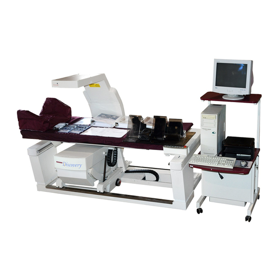
Section 5 - Remove & Replace Printer Monitor Computer Keyboard Power Console Figure 5-17. Operator's Console Assemblies 5-31... -
Page 162: Aperture Assembly Frus
4500 Technical Manual Back View To Scanner Unit Power Supply Optical Drive Controller Comm Controller Bd. Optional Optical I/O Slots Drive Memory Slots 5.25” Floppy Drive 3.5” Floppy Top View Drive JAZ Drive Front View Optical Drive Option Figure 5-18. Computer Assemblies APERTURE ASSEMBLY FRUS This section describes how to remove and replace the FRUs on the Aperture Assembly. -
Page 163: Aperture Motor Pcb
Section 5 - Remove & Replace Motor Shaft Bracket Aperture Stepper Motor Motor Mount Aperture Position Belt Tension Nuts PCB Bracket Clamping Nut Rotary Potentiometer Aperture Motor PCB Figure 5-19. Aperture Assembly FRUs (QDR 4500A and SL) Aperture Motor PCB To remove and replace the Aperture Motor PCB (140-0068) refer to Figure 5-19 and follow the procedure below: 1. -
Page 164: Rotary Potentiometer
4500 Technical Manual 6. Move the aperture towards the potentiometer until it stops. 7. Tighten the belt clamping nut (do not over tighten). 8. Move the aperture back until the motor shaft bracket screw holes line up. 9. Install the 2 Phillips screws holding the motor shaft bracket. Rotary Potentiometer To remove and replace the Rotary Potentiometer (180-0267) refer to Figure 5-19 and follow the procedure below:... -
Page 165: Drum Belts
Section 5 - Remove & Replace Motor Mount Figure 5-20. Aperture Assembly Removal (QDR 4500A and SL) Drum Belts To remove and replace either Drum Belt (130 teeth or 150 teeth) refer to Figure 5-21 and follow the procedure below: 1. -
Page 166: Stepper Motor Assembly
4500 Technical Manual Drum Encoder PCB 140-0065 Encoder Wheel, Inner Encoder Wheel, Outer Figure 5-21. Rear Drum Assembly FRUs 3. Install the Filter Drum Alignment Pin (099-0110), small end first, through the slotted holes and into the small hole at the base plate. If the pin is installed properly, the drum will not rotate. -
Page 167: Drum Bearings
Section 5 - Remove & Replace 6. Refer to the Drum Belts procedure above and replace the belts. Stepper Motor Assembly 010-0627 Idler Arm Belt, 150 Teeth 255-0030 Belt, 130 Teet 255-0031 Drum Motor Mount Figure 5-22. Front Drum Assembly FRUs Drum Bearings To remove and replace the drum bearings refer to Figure 5-22, and Figure 5-23, and follow the procedure below:... -
Page 168: Figure 5-23. Drum Outer Bearings
4500 Technical Manual Note: When replacing the end cap ensure that the flats on each side of the drum shaft are facing the same way (this happens where the two side-by-side holes line up). 11. Replace the 2 endplates. The endplate with the cutout (for the PCB) goes on the drum end away from the alignment hole (see Figure 5-22). -
Page 169: Replacing Emi Cables
Section 5 - Remove & Replace 15. Install the spacers and pulleys at the front endplate (see Figure 5-21). Ensure that the pulley set screws line up with the flat, and use Loctite 222 on set screws. Press the filter drum against the fixture, and the pulley against the endplate, while tightening the set screw. -
Page 170: Figure 5-25. The Emi Compliance Cable
4500 Technical Manual When dressing the cables, be sure the braided shield does not come in contact with any electrical component or voltage source. Cable Connector Ribbon Cable Stripe Copper Shield Ground Lug Braided Shield Figure 5-25. The EMI Compliance Cable 5-40... -
Page 171: Fru Lists
Section 5 - Remove & Replace FRU LISTS The following tables provide the information necessary to identify and order the correct FRU. Please note: The tables are listed by Figure, and then by Cable, Miscellaneous, Mobile, and then Special Tools. If the "Used On"... - Page 172 4500 Technical Manual Figure 5-4. Table X FRUs Used Part Number Description 010-0792 X, Y, R Drive Motor (new, replaces 010-0617) 140-0085 Motor Control Board (EMI, replaces 140-0055) 180-0240 Cable, TX Encoder 255-0021 Table X-drive belt 285-0004 Encoder, Rotary Potentiometer 325-0005 Table X Gearcase Figure 5-5.
- Page 173 Section 5 - Remove & Replace Figure 5-8. C-Arm R FRUs (Inside View) Used Part Number Description 255-0022 Arm Rotation belt 255-0023 Arm Rotation Encoder belt Figure 5-9. Lower C-Arm FRUs Used Part Number Description 010-0575 X-ray Tank 010-0651 Fixed Aperture Filter Drum Assembly 010-0667 Aperture &...
- Page 174 4500 Technical Manual Figure 5-13. Laser Assembly Used Part Number Description 010-0682 Laser Assembly Figure 5-14. Rear C-Arm FRUs Used Part Number Description 140-0087 Analog to Digtl Convrtr Board (ADC, EMI, replaces 140-0054) Figure 5-15. Power Module FRUs Used Part Number Description 101-0032...
- Page 175 Section 5 - Remove & Replace Figure 5-17. Operator's Console Assemblies Used Part Number Description 010-0576 Power Console Assy. 120-0049 Monitor, 17" SVGA 120-0055 Mouse 120-0072 Monitor, 14" SVGA 120-0104 Printer, Color 120-0122 Monitor, 15 in. 120-0124 PRINTER,HP,LASERJET,6P 120-0125 PENTIUM 133MHZ W/WINDOWS 95 120-0127 MONITOR,14"...
- Page 176 4500 Technical Manual Figure 5-18. Computer Assemblies Used Part Number Description 120-0017 Floppy Drive, 1.44MB 3.5" 120-0081 Optical Disk Drive, Internal Half Height 120-0083 SCSI Interface Board 120-0116 Hard Drive, 1GB minimum 120-0120 JAZ Drive, 1GB 120-0145 CD-ROM,12X MINIMUM 120-0148 VIDEO ACCELERATOR, 4 MB PCI 120-0154...
-
Page 177: Cables
Section 5 - Remove & Replace Figure 5-23. Drum Outer Bearings Used Part Number Description 250-0046 Drum Outer Bearing Figure 5-24. Drum Inner Bearings Used Part Number Description 250-0045 Drum Inner Bearing Cables Used Part Number Description 180-0185 Cable, A/D Analog Data 180-0189 Cable, A/D Digital Data 180-0190... -
Page 178: Mobile
4500 Technical Manual Mobile Used Part Number Description 010-0980 ASSY, L'KG PIN Y CARR, MOBILE A,SL 010-0981 ASSY, L'KG PIN C-ARM MOBILE A,SL 010-0993 ASSY,CARR L'KG PIN,MOBILE Special Tools Used Part Number Description 010-0923 X-Ray Beam Alignment Fixture (2 needed) A,SL 099-0110 Filter Drum Alignment Pin... -
Page 179: Section 6 Fault Isolation
BEFORE STARTING Before starting, make sure the software configuration is compatible with the scanner. SOFTWARE CONFIGURATION Check the release number at the top of the Hologic main menu to be sure that it is valid for the scanner model. HARDWARE CONFIGURATION When troubleshooting, it is sometimes helpful to observe all the indicators available on the PCBs and other FRUs. -
Page 180: Motion Problems
4500 Technical Manual The following suggestions apply to a QDR 4500 system exhibiting a power problem: If... Check... Refer to... System "dead” Main breaker Check Power Line Voltage heading, Power switches Section 3 Main power suspect Circuit breakers on power module... -
Page 181: Figure 6-1. Scanner Motion Directions
Section 6 - Fault Isolation motion related problems. The following suggestions apply to a QDR 4500 system that exhibits a motion problem. Start by identifying the bad axis (if it is not obvious). Ask the operator for symptoms and check the error log. - Page 182 However, if the motor encoder is not properly calibrated it may be damaged. TX, TY, TZ, AR, AY To... Run... Refer to... Perform simple table and C-arm Motor Control Pad The Hologic Main Menu, select: movements (computer motion 1. Utility control) 2. Emergency motion Perform precise table and C-arm...
-
Page 183: Control Panel Problems
Section 6 - Fault Isolation CONTROL PANEL PROBLEMS If a Control Panel problem is suspected, or if control panel functions are not responding, use the PANEL command under SQDRIVER to help isolate the problem. From DOS, type: 1. sqdriver<Enter>, then 2. -
Page 184: Vertical Stripe
4500 Technical Manual Vertical Stripe This type of display problem is most likely related to the detector subsystem. The following suggestions apply to a QDR 4500 system that exhibits a vertical stripe in the display: Check... Refer to... Detectors... -
Page 185: No Display
Section 6 - Fault Isolation Check... Refer to... Tube kV peak potential Check Tube kV Peak Potential heading, Section 3 Tube current Tube Current heading, Section 3 X-Ray Beam Alignment (A/SL, C/W) heading, Section 4 X-ray beam alignment Signal strength and noise SUSQ diagnostic in graphic mode Aperture Calibration heading, Section 4 Aperture position and aperture belt... -
Page 186: Targeting/Laser Problems
4500 Technical Manual The following suggestions apply to a QDR 4500 system that exhibits no display: Check... Refer to... Tube kV peak potential Check Tube kV Peak Potential heading, Section 3 Tube current Check Tube Current heading, Section 3... -
Page 187: Area /Bmd/Bmc/Cv Specification Problems
Section 6 - Fault Isolation AREA /BMD/BMC/CV SPECIFICATION PROBLEMS If... Possible cause Refer to... X-ray beam X-ray beam alignment on aperture 11. Signal output level Page 4-1 misaligned should not rise or fall by a significant margin. X-ray beam Measure X-ray peak potential and tube current waveforms. Page 3-17, quality Make sure they are both stable and within specs. -
Page 188: X-Ray Alignment Problems
If not, this may indicate that the X-ray tube has shifted within the letharge. Perform further verification before replacing the X-ray tank. QDR 4500 Figure 6-2. Checking C-Arm Parallelism 3. If the aperture and detector array window are aligned, remove the aperture assembly and inspect the cup and disk. -
Page 189: Beam Flattening Problems
Section 6 - Fault Isolation Verify upper arm parallelism with respect to lower arm assembly. Referring to Figure 6-2, assure dimension x is equal to x System Fails X-Ray Beam Alignment Verification Align the X-ray beam and recalibrate the aperture. If this fails, inspect the aperture assembly for any loose hardware or excessive play in the aperture plate. -
Page 190: Laser Problems
4500 Technical Manual LASER PROBLEMS WARNING: The laser beam can cause serious retina damage if focused directly into the eye. Be sure to turn the laser OFF when visually inspecting the shutter and aperture. When troubleshooting the laser, refer to the following: Make sure... -
Page 191: Oil Leakage
Section 6 - Fault Isolation OIL LEAKAGE If the tank assembly is leaking oil, you may have to tighten the screws on the tank cover. It is important that you tighten the screws using the proper torque specifications and the proper sequence. -
Page 192: Tightening The Lexan Cup Screws
4500 Technical Manual Tightening the Lexan Cup Screws Tighten the Lexan Cup seals in the following order using the torque settings in the above table: Figure 6-4 Lexan Cup Screw Tightening Order Tightening the Bladder Gasket Screws Using the torque settings in the table above and referring to the figure below, tighten the Bladder Gasket screws as follows: 1. -
Page 193: Tightening The Tank Cover Gasket Screws
Section 6 - Fault Isolation The Transformer Screws Figure 6-6. Transformer Screws Tightening the Tank Cover Gasket Screws Refer to the figure below and the torque settings in the table above and tighten the Tank Cover Gasket screws as follows: 1. -
Page 194: Miscellaneous Problems
System No power Check main circuit breaker Check main power cord Check power module circuits breakers MESSAGES The QDR 4500 system software displays three types of messages to the operator: • informational messages • warnings • error messages. Informational messages... -
Page 195: No A/C Line Interrupts
Section 6 - Fault Isolation Displayed in green, they provide information to the user about the operation being performed (see example below). After the message is displayed, normal operation can be resumed, usually by pressing any key. MESSAGE There are no analyzed scans to select for this patient. Press any key to continue Warning messages Displayed in purple, these indicate that an operational problem is about to occur. - Page 196 4500 Technical Manual Jumper Label Possible problem Refer to... Tape switches SECTION 7 Panel Control Panel Table 2-9, Figure 5-2, SECTION 8 Controller Panel Controller C-Arm Interface Board Table 2-10, Figure 2-7, Figure 2-8, Figure 5-8 C-Arm Components connected to SECTION 8 the C-Arm Interface Board Motor Controller PCBs...
-
Page 197: Error Message List
During normal operation, these messages should never appear. If they do, and a suggested action is not provided, call Hologic Technical Support. Include as much information as possible about what was being done at the time the error occurred (including all messages for that error, LOCUS field, message identifier, etc.). - Page 198 Address in the response message did not match the address in the sent message. [E_ADDRESS_MISMATCH_I] Action: This message should be reported to Hologic Technical Support. Include as much information as possible about the scan. Analysis aborted. d0= ___ below acceptable limit.
- Page 199 Hologic Technical Support. Can't open a window Software Error: Ensure that only Hologic software is installed on the computer. If so, report this message to Hologic Technical Support. Include as much information as possible about what you were doing at the time.
- Page 200 __ ..db_VISTA error __ ..Software Error: Any message that begins this way should be reported to Hologic Technical Support. Include as much information as possible about what you were doing at the time. Device already in use by foreground task [E_LOCKOUT_I]...
- Page 201 Action: Verify that the system has been properly calibrated and the normal Hologic system startup procedure has been followed (i.e., reboot the machine and if the problem persists, recalibrate the motor).
- Page 202 IS_xxx command executed from an application (as opposed to executing from a state machine). Action: Verify that the TZ driver has been calibrated and that the correct Hologic system startup procedure has been followed (i.e., reboot the system and if the problem persists, recalibrate the TZ motor).
- Page 203 For the state machine, indicates that one of the self-limiting commands has timed out or that the state machine continued executing into the next cycle. Action: Report this error to Hologic Technical Support. Driver is not installed [E_NOT_INSTALLED_I] Comment: Returned in response to the ON_LINE command to indicate that the MAPI driver is not installed in the system.
- Page 204 Action: Check for disk full. Go to DOS, type DIR D: and check for free space. If the disk is not full, call Hologic Technical Support. Error copying file _________ Hardware Error: There was an error copying the named file.
- Page 205 Action: This can be caused by not enough available memory or an incorrect graphics adapter. Verify that only Hologic software is installed on the system and that the graphics adapter has not been modified. Error in region of interest structure Software Error: This message should be reported to Hologic Technical Support.
- Page 206 The optical file that you are attempting to restore scans from seems to be clobbered. Action: Run diagnostics on the optical drive. If this error recurs, report it to Hologic Technical Support. GetDKernel Internal Software Error GetKernel Internal Software Error Software Error: These messages should be reported to Hologic Technical Support.
- Page 207 Internal Buffer Size Exceeded Software Error: This message should be reported to Hologic Technical Support. Include as much information as possible about what you were doing at the time. Internal device request queue full [E_QUEUE_FULL_I] Comment: The common buffer area for storing system sounds is full.
- Page 208 Report this error to Hologic Technical Support. Internal Error:..Internal Software Error: ..Software Error: Any message that begins this way should be reported to Hologic Technical Support. Include as much information as possible about what you were doing at the time. Internal stack error [E_STACK_ERROR_I]...
- Page 209 One or more detectors is bad. See instructions for running hardware checking program. Invalid identification file. Action: QDR 4500 ID file C:\SQUID.DAT is not valid. Call Hologic Technical Support. Invalid machine type in ARRC.TXT. Action: This is not an error if the machine is not yet calibrated.
- Page 210 Action: If you are running any program other than standard Hologic software, remove it and retry the scan (e.g., do not run a scan while connected to a network or attempt to run a scan under Windows). Otherwise, report this error to Hologic Technical Support.
- Page 211 (Drive A:), try a different diskette. Limit Exceeded: ..Software Error: Any message that begins this way should be reported to Hologic Technical Support. Include as much information as possible about what you were doing at the time. Local motion active [E_LOCAL_MOTION_I]...
- Page 212 4500 Technical Manual Message packet canceled [E_CANCELED_I] Comment: The message packet was canceled before the response was received. This is not an error but merely records the current state of a message packet. The driver normally cancels all outstanding message packets when it goes off line.
- Page 213 If these steps fail, replace the encoder motor. The procedure for these operations can be found in the Remove and Replace section of this manual. If the problem persists, contact Hologic Technical Support.4 Motor is at a limit [E_LIMIT_POSITION_I] Comment: An application tried to move the motor beyond the limit position (i.e., the...
- Page 214 Not enough memory Software Error: Ensure that only Hologic software is installed on the computer. If so, this message should be reported to Hologic Technical Support. Include as much information as possible about what you were doing at the time.
- Page 215 Out of memory Software Error: Ensure that only Hologic software is installed on the computer. If so, this message should be reported to Hologic Technical Support. Include as much information as possible about what you were doing at the time.
- Page 216 PGLINE: ... Software Error: Any message that begins this way should be reported to Hologic Technical Support. Include as much information as possible about what you were doing at the time.
- Page 217 Software Error ..Software Error: Any message that begins this way should be reported to Hologic Technical Support. Include as much information as possible about what you were doing at the time.
- Page 218 NO Motor & Drive board interrupts between them, then this message is produced. Action: Report this error to Hologic Technical Support. Include as much information as possible about what you were doing at the time. Refer to the No A/C Line Interrupts header, page 6-17 in this section.
- Page 219 Unable To Allocate Resources Software Error: This message should be reported to Hologic Technical Support. Include as much information as possible about what you were doing at the time. Unable to Allocate Space for Environment...
- Page 220 Unable to normalize line sums Software Error: This message should be reported to Hologic Technical Support. Include as much information as possible about what you were doing at the time. 6-42...
- Page 221 Section 6 - Fault Isolation Unable to find file Unable to Find Line by Line d0's Unable to Find Previous Analysis Results Unable to Open Tissue Calibration File ________ Unable to open temporary file ________ Unable to open temporary Q-File Unable to Position File to HALO Record Unable to Position Data File Unable to Position File: ________...
- Page 222 There may be a disk problem; appropriate diagnostics should be run. If you are unable to find a hardware problem, the message should be reported to Hologic Technical Support. Include as much information as possible about what you were doing at the time.
- Page 223 Unable to open a window Software Error: Ensure that only Hologic software is installed on the computer. If so, this message should be reported to Hologic Technical Support. Include as much information as possible about what you were doing at the time.
- Page 224 Unrecognized Command Code Software Error: This message should be reported to Hologic Technical Support. Include as much information as possible about what you were doing at the time. Unrecognized device command [E_UNKNOWN_COMMAND_I] Comment: Returned by all devices in response to an unrecognized command.
- Page 225 Section 6 - Fault Isolation X-ray controller is not generating system timing interrupts [E_INTERLOCK_INHIBIT_I] Comment: There have been at least two consecutive system clock ticks (approximately 1/10 second) without any A/C line frequency interrupts from the X-ray controller. Action: Verify that the X-ray controller current fuse on the operator console is not "popped".
-
Page 227: Section 7 Preventive Maintenance
Hologic requires that the customer run a daily QC scan of the spine phantom supplied with the QDR 4500, and add that scan to the QC database. If the CV of the database exceeds 0.8% the customer is asked to apprise Hologic Field Service. -
Page 228: Guide Rail And Bearing Maintenance
4500 Technical Manual those from the last PM for possible problems, and keep the printouts with the service records for this system. [ ] During a scan, verify that pressing the red emergency STOP switch, or turning the X- RAY ENABLE key-switch to OFF, immediately stops all carriage motion and X-ray production. -
Page 229: Figure 7-1. Guide Bearing And Rail
Section 7 - Preventive Maintenance 1. Clean the AY and the TX guide rails using a dry, clean cloth. Note: DO NOT use a solvent such as alcohol or WD-40. If a solvent is needed to remove dirt and/or gum buildup on the rail, be sure to thoroughly dry the rail before moving the bearings. -
Page 231: Section 8 Pcb Summary Information
SECTION 8 PCB SUMMARY INFORMATION Power Distribution LEDs Signal Voltage Source Jacks Refer to... +24VDC Power A/SL All used Figure Console XRAY JP9 not 5-14, 5-15 ENABLE used +15VDC Power Console -15VDC Power Console +28VDC Power Console LEDs Voltage Voltage Source Jumpers Refer to... -
Page 232: Signal Distribution
4500 Technical Manual Signal Distribution LEDs Signal Voltage Source Jumpers Refer to... +7VDC Int. Voltage Reg. JP1 (panel) TZ drive JP2 (dist) +5VDC Int. Voltage Reg. JP3 (C-arm) +28VDC Ext Console Figure Power Circuit Breakers +15VDC Ext Console CB Drive Normally Power -15VDC Ext Console... -
Page 233: Detector Array Assembly
Section 8 - PCB Summary Information Detector Array Assembly Voltage Refer To... /Signal Source +15VDC Ext. ADC PCB -15VDC Ext. ADC PCB Figure 5-10 +5VDC Ext. ADC PCB +12VDC Int. Voltage Reg. -12VDC Int. Voltage Reg. TZ Drive Voltage /Signal LEDs Source Jumpers... -
Page 234: Stepper Motor Controller
4500 Technical Manual Stepper Motor Controller LEDs Signal Source Jumpers and Refer to... Switches +28VDC Ext Signal Dist. W1 (SYSRESET) +5VDC Int. Voltage Reg. -5VDC Int. Voltage Reg. D7 (4 LED pack) Note: All 4 LEDs are On Flash solid when the selected motor drive is engaged. - Page 235 Section 8 - PCB Summary Information C-Arm Interace LEDs Signal Voltage Source Jumpers Refer to... +28VDC Signal Dist. DRUM +24VDC Signal Dist. MAIN +5VDC Int. Voltage NORMAL(1-2) Reg. TEST (2-3) +7VDC Int. Voltage SYS- Reg. RESET +15VDC Signal Dist. TEST- MODE -15VDC Signal Dist.
-
Page 237: Section 9 Software Tools
SECTION 9 SOFTWARE TOOLS The Hologic system software includes software tools to troubleshoot the system. They are: • SUSQ • SQKEYPAD SUSQ For a more detailed description of the SUSQ utility, refer to the SUSQ Diagnostic Program reference guide. Starting SUSQ At the Hologic Main Menu: 1. -
Page 238: Figure 9-1. Susq Screen−X-Rays Off
4500 Technical Manual X-Ray Controller Status VOLTS 0001100100010011 Value N Mean StdDev Hi Bone 0.9799 7 0.9790 0.0006 0.0665 Lo Bone 0.9793 7 0.9791 0.0004 0.0401 Hi Tissue 0.9784 6 0.9787 0.0003 0.0312 Lo Tissue 0.9787 7 0.9790 0.0004 0.0397 Hi Air 0.9786... -
Page 239: Figure 9-3. Susq Screen Settings
Section 9 - Software Tools Testing the QDR 4500 System in SURVEY (SUSQ) X-Ray Controller Status VOLTS 0001100100010011 Value N Mean StdDev Hi Bone 0.9799 7 0.9790 0.0006 0.0665 Lo Bone 0.9793 7 0.9791 0.0004 0.0401 Hi Tissue 0.9784 6 0.9787 0.0003... -
Page 240: Sqkeypad
4500 Technical Manual SQKEYPAD The SQKEYPAD utility allows you to control motor functions and turn on the laser. If there is a problem TABLE TABLE with the Operator Control Panel, use this utility to LATERAL isolate a panel or a motion problem. Note: SQKEYPAD will not work for some motor LASER TABLE... -
Page 241: Appendix Asoftware Deinstallation/Installation
APPENDIX A SOFTWARE DEINSTALLATION/INSTALLATION This appendix describes to steps used to deinstall and reinstall the Hologic operating system software versions V9.10 and V9.8. Deinstalling Hologic V9.10/V9.8 Do the following: Perform a dBarchive. At the Windows Taskbar, select Start, then Programs, then the MS-DOS prompt. - Page 242 12. Insert the first disk of the Elite System Upgrade (V9.8). 13. Follow the instructions on the screen and reboot the computer when prompted. 14. At the Hologic main menu, go to Utility, then Service, then dbManagement, then dbRecover. 15. Insert the last (or only) dBarchive disk into the drive and press Enter. Press Enter again to do a complete database recovery.
-
Page 243: Appendix Bcross-Calibration
QC on the NEW QDR. The NEW PHANTOM should be shipped back to the factory along with the de-installed ORIGINAL QDR. Definition Summary FAN-BEAM SYSTEM QDR 2000, 2000plus, 4500. NON-FAN-BEAM SYSTEM QDR 1000, 1000plus, 1000/W, 1500, 4000. For this procedure only, a QDR means any Hologic fan-beam system. - Page 244 4500 Technical Manual NEW QDR A Hologic fan-beam system just installed, typically a QDR 4500. ORIGINAL QDR An existing Hologic fan-beam system, typically a QDR 2000 or 2000plus. NEW PHANTOM The phantom that came with the NEW QDR. ORIGINAL PHANTOM The phantom that came with the ORIGINAL QDR.
- Page 245 Appendix B – Cross-Calibration function in QC to get an average over at least one month of QC data. Use this option only if: 1) the QC data has been stable, 2) there has been no recent re-calibrations or field service, and 3) QC has been performed on a regular basis.
- Page 246 4500 Technical Manual STEP 1 - Check the ORIGINAL QDR's Calibration and Save its Patient Database Step 2 - Transfer the ORIGINAL QDR's database to the NEW QDR. Note: This step should only be performed if the ORIGINAL QDR is being removed from the site (deinstalled).
- Page 247 Appendix B – Cross-Calibration SCANSQ -pap7sp60 -l6 -n10<Enter> d. Analyze the 10 scans manually with compare or use autocomp. To use autocomp, analyze the first scan, exit to DOS and type: AUTOCOMP 10 <Enter> e. Verify that the BMD of the 10 scans is within +/- 2.0 % of the factory value written on the label and that the CV is less than 0.5%.
- Page 248 4500 Technical Manual b. Enter the ORIGINAL PHANTOM height printed in Step 1.3f into the NEW QDR system and Press <F10>. Enter the measured height for phantom # xxxx : 6.78 c. Verify that the Array phantom information is correct and press “Y” to continue. d.
- Page 249 Appendix B – Cross-Calibration STEP 4 - Re-label the QDR PHANTOM Note: This step is unnecessary if the customer intends to use the ORIGINAL PHANTOM to perform daily QC measurements on the NEW QDR. It is only required if the customer intends to use the NEW PHANTOM for daily QC on the NEW QDR system.
- Page 250 4500 Technical Manual 4.12 Enter QC from the main menu. Verify that the QC program asks for the QDR phantom serial number. Perform a daily QC scan according to the instructions on the monitor. After the scan has been analyzed press <Enter> to add the scan to the QC database. Inspect the database to ensure that the scan is within the QC limits setup in Step 4.9.
Need help?
Do you have a question about the QDR 4500 and is the answer not in the manual?
Questions and answers