Hologic Affirm User Manual
Breast biopsy guidance system
Hide thumbs
Also See for Affirm:
- User manual (194 pages) ,
- Service manual (116 pages) ,
- User manual (70 pages)
Table of Contents
Advertisement
Advertisement
Table of Contents

Related Manuals for Hologic Affirm


Summary of Contents for Hologic Affirm
- Page 1 User Guide MAN-06411-002 Revision 003...
- Page 3 Affirm ® Breast Biopsy Guidance System User Guide For Software Versions 1.11 and 2.2 Part Number MAN-06411-002 Revision 003 July 2021...
- Page 4 Hologic, 3Dimensions, Affirm, ATEC, Brevera, Dimensions, Eviva, Selenia, and associated logos are trademarks and/or registered trademarks of Hologic, Inc., and/or its subsidiaries in the United States and/or other countries. All other trademarks, registered trademarks, and product names are the property of their respective owners.
-
Page 5: Table Of Contents
Affirm Breast Biopsy Guidance System User Guide Table of Contents Table of Contents List of Figures _________________________________________________________________ ix List of Tables __________________________________________________________________ xi 1: Introduction __________________________________________________________________1 Intended Use................................1 User Profiles................................1 1.2.1 Mammography Technologist ........................1 1.2.2 Radiologists, Surgeons ..........................1 1.2.3... - Page 6 Biopsy Control Module .......................... 37 3.6.2 Biopsy Guidance Module ........................37 Tabletop Stand for the Affirm System ....................... 38 Storage Case for the Lateral Arm ........................39 4: User Interface - Biopsy Control Module ________________________________________41 Biopsy Control Module Screens .......................... 41 4.1.1...
- Page 7 Affirm Breast Biopsy Guidance System User Guide Table of Contents For General Cleaning ............................82 7.4.1 How to Clean the Biopsy Control Module Screen ................82 7.4.2 To Prevent Possible Injury or Equipment Damage ................83 Appendix A: System Specifications ______________________________________________85 Affirm System Measurements ..........................
-
Page 9: List Of Figures
Table of Contents List of Figures Figure 1: Affirm Biopsy System on the Selenia Dimensions Mammography System ..........7 Figure 2: How to Lift the Biopsy Guidance Module ..................... 8 Figure 3: How to Store the Biopsy Guidance Module ....................8 Figure 4: Biopsy Guidance Module Label Location .................... - Page 10 Figure 71: Lateral QAS Button on the Admin Screen ....................75 Figure 72: Lateral QAS Test Info Dialog Box ....................... 76 Figure 73: Device Field in the Biopsy Tab ........................76 Figure 74: Affirm Biopsy Guidance Module ........................ 85 Figure 75: Lateral Arm ..............................86 MAN-06411-002 Revision 003...
-
Page 11: List Of Tables
Table 9: Radiologic Technologist Preventive Maintenance Schedule............... 80 Table 10: Service Engineer Preventive Maintenance Schedule ................. 81 Table 11: Affirm System Audible Alerts ........................89 Table 12: Affirm System Error Messages ........................89 Table 13: Acquisition Workstation Messages ......................91 Table 14: Hologic Factory-Verified Biopsy Devices .................... -
Page 13: 1: Introduction
Physicians should tell patients about all potential risks and adverse events described in this manual with respect to the operation of the system. Note Hologic configures some systems to meet specific requirements. Your system configuration may not have all the options and accessories included in this manual. Intended Use Caution: United States federal law restricts this device to sale by or on the order of a physician. -
Page 14: Medical Physicist
Additionally, the user manual is a guide for directions on how to use the system. All users must make sure that they receive training on correct operation of the system before use on patients. Hologic does not accept the responsibility for injury or damage from incorrect system operation. Quality Control Requirements Perform all Quality Control tests within the correct time frame. -
Page 15: Warranty Statement
Hologic specifications or instructions, including Customer’s refusal to allow Hologic recommended Software upgrades; or (d) designated as supplied subject to a non-Hologic warranty or on a pre- release or “as-is” basis. Technical Support Refer to the copyright page of this manual for contact information for product support. -
Page 16: Symbols
Potential Equalization terminal Protective Earth terminal "On" and "Off" (power) for the computer and display. Discard electrical and electronic equipment separately from standard waste. Send decommissioned material to Hologic or contact your service representative. Manufacturer Date of Manufacture Catalog number... -
Page 17: Descriptions Of Warnings, Cautions, And Notes
Affirm Breast Biopsy Guidance System User Guide Chapter 1: Introduction 1.11 Descriptions of Warnings, Cautions, and Notes Descriptions of Warnings, Cautions, and Notes used in this manual: WARNING! The procedures that you must follow accurately to prevent possible dangerous or fatal injury. -
Page 19: 2: General Information
During a standard needle approach procedure, motors in the Affirm system move the biopsy device in X and Y directions. Z-axis movement is manual. The optional Affirm Lateral Arm Upright Biopsy Accessory installs on the biopsy guidance module to enable lateral needle approach procedures. -
Page 20: How To Handle The Biopsy Guidance Module
Biopsy Guidance Module. Caution: The Affirm Biopsy Guidance Module weighs 15 pounds. When you move it, be sure to have a secure grip on the handles. Only lift the Biopsy Guidance Module with the handles. -
Page 21: Safety Information
Read and understand this manual before you use the system. Keep the manual available during the patient procedures. Always follow all the instructions in this manual. Hologic does not accept the responsibility for injury or damage from incorrect system operation. Hologic can schedule training at your facility. -
Page 22: Compliance
Caution: To prevent damage or misalignment, be careful when you move the Affirm system. Caution: The Affirm Biopsy Guidance Module weighs 15 pounds. When you move it, be sure to have a secure grip on the handles. Note The system does not have any parts that are serviced by the user. -
Page 23: Label Locations
Affirm Breast Biopsy Guidance System User Guide Chapter 2: General Information Label Locations Figure 4: Biopsy Guidance Module Label Location Figure 5: Lateral Arm Serial Number Label Location MAN-06411-002 Revision 003 Page 11... -
Page 25: 3: Installation, Verification, And Removal
Affirm Breast Biopsy Guidance System User Guide Chapter 3: Installation, Verification, and Removal Chapter 3 Installation, Verification, and Removal Biopsy Guidance Module Components The Biopsy Guidance Module installs on the front of the C-arm of the Selenia Dimensions and 3Dimensions systems. A lock lever (see the following figure, item 8) secures the module in position. -
Page 26: Table 1: Components Of The Biopsy Guidance Module
Affirm Breast Biopsy Guidance System User Guide Chapter 3: Installation, Verification, and Removal Table 1: Components of the Biopsy Guidance Module Name Description Two on each side hold the Biopsy Guidance Module on the Attachment Hooks imaging system Gantry. Handles One on each side. -
Page 27: Biopsy Control Module Components
Affirm Breast Biopsy Guidance System User Guide Chapter 3: Installation, Verification, and Removal Biopsy Control Module Components The Biopsy Control Module attaches to either the left or right handle on the Biopsy Guidance Module with a bracket (item 5). The display screen (item 2) is a touch screen for the user to perform the desired tasks. -
Page 28: Installation Of The Main Components
Slide the top hooks (item 2) of the Biopsy Guidance Module into the slots marked with the Affirm system icon (item 2A) on the front of the imaging system C-arm. Make sure the top and bottom hooks attach to the C-arm. -
Page 29: Attach The Biopsy Control Module
Affirm Breast Biopsy Guidance System User Guide Chapter 3: Installation, Verification, and Removal 3.3.2 Attach the Biopsy Control Module The Biopsy Control Module attaches to either the left or right handle of the Biopsy Guidance Module. Figure Legend Lock Knob for the Articulating Arm... -
Page 30: Installation And Removal Of Accessories
Affirm Breast Biopsy Guidance System User Guide Chapter 3: Installation, Verification, and Removal Adjust the Bracket Height Release the Attachment Bracket Lock (see the previous figure, item 5). Slide the bracket to the required height. Push the Attachment Bracket Lock into the locked position. -
Page 31: Figure 10: Installation Of The Needle Guide Holder On The Standard Device Mount
Affirm Breast Biopsy Guidance System User Guide Chapter 3: Installation, Verification, and Removal Installation of the Needle Guide on the Standard Needle Guide Holder Insert the needle guide rods of the needle guide holder into the standard device mount (slide in from the bottom). -
Page 32: Biopsy Device Adapter
Affirm Breast Biopsy Guidance System User Guide Chapter 3: Installation, Verification, and Removal 3.4.3 Biopsy Device Adapter Installation of the Biopsy Device Adapter on the Standard Device Mount Align the outer holes in the biopsy device adapter (item 1 in the following figure) with the guide pins on the device mount. -
Page 33: Lateral Arm And Lateral Arm Accessories
Affirm Breast Biopsy Guidance System User Guide Chapter 3: Installation, Verification, and Removal 3.4.5 Lateral Arm and Lateral Arm Accessories Warning: Be careful when working with the Lateral Arm. Bumping or jarring the Lateral Arm can affect system accuracy, cause patient injury, or cause equipment damage. -
Page 34: Table 3: Components Of The Lateral Arm
Affirm Breast Biopsy Guidance System User Guide Chapter 3: Installation, Verification, and Removal Table 3: Components of the Lateral Arm Name Description Mounting structure for the Lateral Arm. Attaches to the Standard Lateral Arm Mount Device Mount and holds the Lateral Arm on the Biopsy Guidance Module. -
Page 35: Figure 14: Left Needle Approach Of Lateral Arm (Blue)
Affirm Breast Biopsy Guidance System User Guide Chapter 3: Installation, Verification, and Removal The Lateral Arm can be mounted to the left or the right side of the Biopsy Guidance Module to permit a lateral needle approach from either direction. Determine the desired approach before mounting the Lateral Arm and install the Biopsy Control Module on the opposite side from the desired approach. -
Page 36: Figure 16: Installing The Lateral Arm Stand Over The Image Receptor
Affirm Breast Biopsy Guidance System User Guide Chapter 3: Installation, Verification, and Removal Lateral Arm Warning: Clean the Lateral Arm before and after every use (refer to For General Cleaning on page 82). Installation of the Lateral Arm Make sure that the C-arm is set to 0 degrees. -
Page 37: Figure 17: Removing The Needle Guide Holder From The Standard Device Mount
Affirm Breast Biopsy Guidance System User Guide Chapter 3: Installation, Verification, and Removal On the Affirm system, remove the needle guide holder used on the standard device mount. Figure 17: Removing the Needle Guide Holder from the Standard Device Mount Determine the direction of approach of the biopsy device (left or right side of the Biopsy Guidance Module). -
Page 38: Figure 18: Installing The Lateral Arm On The Device Mount
Affirm Breast Biopsy Guidance System User Guide Chapter 3: Installation, Verification, and Removal Attach the Lateral Arm to the Biopsy Guidance Module (see the following figure). Align the top and bottom guide holes on the Lateral Arm (item 1 in the following figure) to the top and bottom pins on the device mount on the Biopsy Guidance Module. -
Page 39: Figure 19: Selection Screen For The Lateral Arm Mounting Side
Affirm Breast Biopsy Guidance System User Guide Chapter 3: Installation, Verification, and Removal On the Biopsy Control Module, select the correct Lateral Arm Mounting Side button for the side the Lateral Arm is mounted on. Figure 19: Selection Screen for the Lateral Arm Mounting Side On the Biopsy Control Module, select OK to confirm that the Lateral Arm Stand is installed. -
Page 40: Figure 20: Attaching The Blue Needle Guide Holder To The Needle Guide Rods (Left Needle Approach)
Affirm Breast Biopsy Guidance System User Guide Chapter 3: Installation, Verification, and Removal Needle Guide for the Lateral Arm Warning: Always use sterile techniques when you use Needle Guides during the patient procedures. Warning: It is important to install the device correctly. Be sure to insert the needle through the top and bottom Needle Guides. -
Page 41: Figure 22: Installing A Disposable Needle Guide On A Needle Guide Holder (Lateral Arm)
Affirm Breast Biopsy Guidance System User Guide Chapter 3: Installation, Verification, and Removal Slide the disposable needle guide (item 1) over the pin on the end of the needle guide holder (item 2). Figure Legend 1. Disposable Needle Guide 2. Needle Guide Holder... -
Page 42: Figure 23: Carriage Lever Locked And Unlocked Positions
Affirm Breast Biopsy Guidance System User Guide Chapter 3: Installation, Verification, and Removal Device Mount for the Lateral Arm Installation of the Device Mount Flip the Carriage lever completely up to the unlocked position. Figure 23: Carriage Lever Locked and Unlocked Positions... -
Page 43: Figure 25: Installing Device Mount Onto Lateral Arm Carriage
Affirm Breast Biopsy Guidance System User Guide Chapter 3: Installation, Verification, and Removal Slide the device mount onto the Lateral Arm Carriage until it stops. Figure 25: Installing Device Mount onto Lateral Arm Carriage Note The device mount must be installed with the needle guide in front of the Lateral Arm. -
Page 44: Figure 26: Attaching The Biopsy Device Adapter To The Device Mount (Lateral Arm)
Affirm Breast Biopsy Guidance System User Guide Chapter 3: Installation, Verification, and Removal Biopsy Device Adapter Installation of the Biopsy Device Adapter Align the outer holes in the biopsy device adapter (item 1 in the following figure) with the guide pins on the device mount. -
Page 45: Figure 27: Lock Levers In Fully Locked Position
Affirm Breast Biopsy Guidance System User Guide Chapter 3: Installation, Verification, and Removal Biopsy Device Follow the directions supplied by the manufacturer to install or remove the biopsy device and adapter. Carefully insert the biopsy needle through the disposable needle guide when installing the biopsy device. -
Page 46: Figure 28: Scales And Positioning For The X-Stop And Carriage
Affirm Breast Biopsy Guidance System User Guide Chapter 3: Installation, Verification, and Removal X-Stop The X-Stop is an accessory that stops movement of the Carriage and the device mount along the Lat X axis. The X-Stop Position Indicator is used to position the X-Stop along the bottom scale of the Lateral Arm. -
Page 47: Figure 29: Installing The X-Stop On The Lateral Arm
Affirm Breast Biopsy Guidance System User Guide Chapter 3: Installation, Verification, and Removal Installation of the X-Stop Make sure that the X-Stop lever is fully in the unlocked (up) position. Slide the X-Stop onto the Lateral Arm on the same side as the Lateral Arm mount. -
Page 48: System Verifications
System Verifications 3.5.1 Confirm the Host Connection When the imaging system is On and the Affirm system cable connections are correct, the Home screen shows on the Biopsy Control Module. Figure 30: Home Screen on the Biopsy Control Module Page 36... -
Page 49: Removal Of The Main Components
Biopsy Guidance Module. Caution: The Affirm Biopsy Guidance Module weighs 15 pounds. When you move it, be sure to have a secure grip on the handles. To remove the Biopsy Guidance Module from the imaging system C-arm: Disconnect the Biopsy Guidance Module Cable from the C-arm. -
Page 50: Tabletop Stand For The Affirm System
Caution: The Affirm system Tabletop Stand is not for mobile applications. To place the Affirm biopsy system on the optional stand, see the following figure. Move the device mount and needle guide to the highest upper position as shown in Disconnect the biopsy guidance module cable from the imaging system C-arm. -
Page 51: Storage Case For The Lateral Arm
Affirm Breast Biopsy Guidance System User Guide Chapter 3: Installation, Verification, and Removal Storage Case for the Lateral Arm The Lateral Arm is supplied with a storage case to safely store all the Lateral Arm components. The Lateral Arm QAS Phantom is also stored in the storage case. To protect the equipment and to maintain accuracy, always store the Lateral Arm and its components in its case. -
Page 53: 4: User Interface - Biopsy Control Module
Affirm Breast Biopsy Guidance System User Guide Chapter 4: User Interface - Biopsy Control Module Chapter 4 User Interface - Biopsy Control Module Biopsy Control Module Screens 4.1.1 Home Screen The Home screen shows the name or initials of the user who logs in and any error messages. -
Page 54: Target Guidance Screen
Affirm Breast Biopsy Guidance System User Guide Chapter 4: User Interface - Biopsy Control Module 4.1.2 Target Guidance Screen The following figure shows the main screen of the Biopsy Control Module. This screen shows the current position of the biopsy device, the selected target coordinates and the Cartesian difference between the two positions. -
Page 55: Figure 35: Target Guidance Screen For Lateral Arm
Affirm Breast Biopsy Guidance System User Guide Chapter 4: User Interface - Biopsy Control Module Note The X, Y, and Z cells in the screen can change color as target coordinates change. Refer Colored Cells in the Screens on page 44. -
Page 56: Figure 36: Green Differential Cells
Affirm Breast Biopsy Guidance System User Guide Chapter 4: User Interface - Biopsy Control Module Colored Cells in the Screens Green Cells When all Diff cells are green, the biopsy device is in the correct position for the selected target. When the biopsy device is fired, the target is at the center of the aperture of the device. -
Page 57: Figure 38: Alert Sounds Are Audible
Affirm Breast Biopsy Guidance System User Guide Chapter 4: User Interface - Biopsy Control Module The Sound Button The Sound button is enabled when there is a system fault. When the Sound button displays, you can control system sounds related to alarms and motor movements of the biopsy device. -
Page 58: Jog Mode Screen
Affirm Breast Biopsy Guidance System User Guide Chapter 4: User Interface - Biopsy Control Module 4.1.3 Jog Mode Screen This screen allows the user to manually overwrite the targeting coordinates of the Biopsy Guidance Module. The arrow buttons in the Jog Mode screen change the Jog value of the X and Y coordinates. -
Page 59: Figure 41: Jog Mode Screen For Lateral Arm
Affirm Breast Biopsy Guidance System User Guide Chapter 4: User Interface - Biopsy Control Module Figure Legend 1. Change Y-axis Jog value in negative direction 2. Change X-axis Jog value in negative direction 3. Change Y-axis Jog value in positive direction 4. -
Page 60: Select Target Screen
Affirm Breast Biopsy Guidance System User Guide Chapter 4: User Interface - Biopsy Control Module 4.1.4 Select Target Screen This screen allows the user to select a different target for biopsy guidance or to move to one of the Home positions. The buttons in the Select Target screen allow the user to go to the previous screen (item 1), go to the Target screen (item 2), or go to the Left or Right Home Position (item 3 or item 6). - Page 61 Affirm Breast Biopsy Guidance System User Guide Chapter 4: User Interface - Biopsy Control Module Figure 43: Select Target Screen for Lateral Arm When the Lateral Arm is installed, the target coordinate icons on the Select Target screen include a line for the Lat X value.
-
Page 63: 5: Biopsy
Affirm Breast Biopsy Guidance System User Guide Chapter 5: Biopsy Chapter 5 Biopsy Biopsy Views When performing a 2D biopsy procedure, the biopsy guidance system requires stereo views. Stereo views are images taken at +15° and -15° angles. Collectively, these two images are called a stereo pair. -
Page 64: Add A Biopsy View
Affirm Breast Biopsy Guidance System User Guide Chapter 5: Biopsy 5.1.1 Add a Biopsy View To Add a Biopsy View: In the Procedure screen, select the Add View button to display the Add View screen. Figure 44: Biopsy Tab in the Add View Screen Figure Legend 1. - Page 65 Affirm Breast Biopsy Guidance System User Guide Chapter 5: Biopsy Add a Stereo Biopsy Half-Pair View You can add a view to acquire a single -15° or +15° Stereotactic 2D biopsy image. This view allows you to create a target using the Stereotactic Scout and the single Stereotactic 2D view.
-
Page 66: Edit A Biopsy View
Affirm Breast Biopsy Guidance System User Guide Chapter 5: Biopsy 5.1.2 Edit a Biopsy View Use the Edit View screen to assign a different view to an image. Figure 46: Edit (Biopsy) View Screen To Edit a View: In the Procedure screen, select an exposed thumbnail image view. -
Page 67: C-Arm Stereo Modes
Affirm Breast Biopsy Guidance System User Guide Chapter 5: Biopsy C-Arm Stereo Modes Acquire the stereo images in either the Auto C-arm Stereo Mode or the Manual C-arm Stereo Mode. Make the C-arm Stereo Mode selection at the Acquisition Workstation... -
Page 68: Table 5: The C-Arm Stereo Mode Button
Affirm Breast Biopsy Guidance System User Guide Chapter 5: Biopsy In Manual C-Arm Stereo Mode In Manual C-arm Stereo Mode, the C-arm Stereo Mode button shows on the Target Guidance screen. The default is Stereo Mode. Refer to the table that follows for a description of the button function. -
Page 69: How To Select The C-Arm Stereo Mode For Image Acquisition
Affirm Breast Biopsy Guidance System User Guide Chapter 5: Biopsy 5.2.2 How to Select the C-Arm Stereo Mode for Image Acquisition Table 6: How to Select the C-Arm Stereo Mode 1. Select the System Status icon. Figure 49: System Status Icon 2. -
Page 70: Biopsy Tab
Affirm Breast Biopsy Guidance System User Guide Chapter 5: Biopsy Biopsy Tab Figure Legend 1. Target Function Buttons 2. Biopsy Options Area Figure 52: The Biopsy Tab When you select the Biopsy tab in the Procedure screen, the Biopsy Options appear. The Biopsy Options area of the screen shows information about the targets and the biopsy device installed on the system. -
Page 71: Biopsy Options
Affirm Breast Biopsy Guidance System User Guide Chapter 5: Biopsy 5.3.1 Biopsy Options The buttons in the Biopsy Options area communicate target information to the Biopsy Control Module. The area on the right side of the buttons shows the selected target and biopsy device. - Page 72 Affirm Breast Biopsy Guidance System User Guide Chapter 5: Biopsy Figure Legend Create Target assigns target point(s) and creates a target icon in the target set (item 10). After you assign your target, click the button a second time to accept the target and transfer the target coordinates to the Biopsy Control Module.
- Page 73 Red indicates that the current coordinates exceed the safety • margin. Yellow warns of being near the safety limit. • Note To make a target active for the Affirm system, select a target icon from the target set and click the Resend button. MAN-06411-002 Revision 003 Page 61...
-
Page 74: Stereotactic 2D Lesion Targeting
Affirm Breast Biopsy Guidance System User Guide Chapter 5: Biopsy Stereotactic 2D Lesion Targeting Note You can use the Zoom tool (in the Tools tab or View Actual Pixels button) to magnify the area of interest in an image. Note If the exam data in the image blocks detection of the lesion, click the Information icon in the Tools tab to hide the data. -
Page 75: Verify The Position Of The Biopsy Device
Affirm Breast Biopsy Guidance System User Guide Chapter 5: Biopsy 5.4.1 Verify the Position of the Biopsy Device If desired, use the following steps to verify the position of the biopsy device. Acquire the pre-fire images as necessary to identify the correct needle position. -
Page 76: Lesion Targeting With Tomosynthesis Guidance
Affirm Breast Biopsy Guidance System User Guide Chapter 5: Biopsy Lesion Targeting with Tomosynthesis Guidance Lesion targeting for tomosynthesis guided procedures requires system licenses for tomosynthesis and biopsy. Note Make sure that the biopsy device is out of the imaging area. -
Page 77: Verify The Position Of The Biopsy Device
Affirm Breast Biopsy Guidance System User Guide Chapter 5: Biopsy 5.5.1 Verify the Position of the Biopsy Device If desired, use the following steps to verify the position of the biopsy device. Acquire the pre-fire images as necessary to identify the correct needle position. -
Page 78: Lesion Targeting Using Multi-Pass
Affirm Breast Biopsy Guidance System User Guide Chapter 5: Biopsy Lesion Targeting Using Multi-Pass Note The Multi-Pass feature is not available when using the Lateral Arm. Note The overall targeting accuracy is equal to the combined targeting accuracy of the Biopsy Guidance Module and the biopsy device. - Page 79 Affirm Breast Biopsy Guidance System User Guide Chapter 5: Biopsy Select the number of offset target points (three, four, or five) you require around the center target point. Figure 56: Four Offset Target Points Established Around Center Target Point Note Keep in mind that the center target point is included in the total target points.
- Page 80 Affirm Breast Biopsy Guidance System User Guide Chapter 5: Biopsy The crosshairs pattern for the target changes when the target is selected or deselected. See the following figures. Figure 59: Single Figure 60: Single Figure 61: Multi-Pass Figure 62: Multi-Pass...
- Page 81 Affirm Breast Biopsy Guidance System User Guide Chapter 5: Biopsy The biopsy order of the target points is as follows: • The number displayed at the bottom right of the crosshairs circle indicates the order between target sets. The first target is labeled "1", the second is "2", and so on.
-
Page 82: Post Biopsy
Affirm Breast Biopsy Guidance System User Guide Chapter 5: Biopsy Post Biopsy Put in a biopsy site marker, if desired. Move the biopsy device away from the breast. Acquire images as necessary. Release compression. Printing Stereo Pair Images When you select a stereo pair from the thumbnail area of the Print screen, the image mode buttons change. -
Page 83: 6: Quality Control
Affirm Breast Biopsy Guidance System User Guide Chapter 6: Quality Control Chapter 6 Quality Control MQSA has no requirements for interventional procedures (such as breast biopsy). If your facility is ACR accredited for breast biopsy, refer to the 1999 ACR Stereotactic Breast Biopsy Quality Control Manual on how to do quality control. -
Page 84: Qas Test For Standard Needle Approach
If you use a QAS Needle Phantom, do not extend the needle unless it is attached to the Biopsy Guidance Module and the module is installed on the C-arm. Make sure the Affirm system is installed correctly and all paddles are removed. On the Acquisition Workstation, from the Select Patient screen, select the Admin button. - Page 85 Install the QAS Phantom. (If the QAS Phantom uses a needle, fully extend the needle.) In the Info dialog box, select OK. On the QAS screen, select the Biopsy tab. Make sure that Affirm QAS appears in the Device field. Figure 70: Device Field in the Biopsy Tab Press and hold a right or left Motor Enable button pair on the Biopsy Control Module.
- Page 86 If the targeting coordinates are not within ± 1 mm, contact Technical Support. Do not try to adjust the system. Do not perform any biopsy procedure with the Affirm system until Technical Support indicates the system is ready for use.
-
Page 87: Qas Test For Lateral Needle Approach
Chapter 6: Quality Control 6.2.2 QAS Test for Lateral Needle Approach Make sure the Affirm system is installed correctly and all paddles are removed. On the Acquisition Workstation, navigate to the Admin screen. Select the Lateral QAS button. Figure 71: Lateral QAS Button on the Admin Screen... - Page 88 Install the Lateral Arm assembly and the Lateral Arm QAS Phantom on the left side of the Affirm system. In the Info dialog box, select OK. On the QAS screen, select the Biopsy tab. Make sure that Affirm Lateral QAS appears in the Device field. Figure 73: Device Field in the Biopsy Tab Press and hold a right or left Motor Enable button pair on the Biopsy Control Module.
- Page 89 13. Repeat steps 11 and 12 for all unexposed views for that approach side. 14. Move the Lateral Arm assembly to the right side of the Affirm system. Repeat steps 5 through 13. 15. At the Acquisition Workstation, select the End QC button.
-
Page 90: Geometry Calibration
Affirm Breast Biopsy Guidance System User Guide Chapter 6: Quality Control Geometry Calibration Geometry calibration is required semiannually. Perform this calibration using the Geometry phantom supplied with the system. 6.3.1 Geometry Calibration Procedure Inspect the calibration phantom for damage. Select Admin > Quality Control > Technologist tab > Geometry Calibration procedure on the Acquisition Workstation. -
Page 91: 7: Care And Cleaning
Inspect the Biopsy Paddle for damage before use. Inspect the calibration Phantom for damage. Inspect all cables for wear and damage before use. Make sure that the Affirm system locks in position. Make sure that the Needle Guides are installed correctly before use. -
Page 92: Table 9: Radiologic Technologist Preventive Maintenance Schedule
Affirm Breast Biopsy Guidance System User Guide Chapter 7: Care and Cleaning Lateral Arm Table 9: Radiologic Technologist Preventive Maintenance Schedule Each Maintenance Task Description Daily Semiannually Clean all Lateral Arm components with a disinfectant after use.* Make sure that all locks and controls function and move smoothly. -
Page 93: Service Preventive Maintenance Schedule
Check compression lockout operation. Verify the Affirm system alignment to the C-arm. Verify the Needle Guide alignment. Verify the Affirm system locks in position on the C-arm. Verify the ID sensors correctly identify the Affirm system when installed. Install software/ firmware upgrades if required and if under warranty/contract. -
Page 94: For General Cleaning
Caution: Use the least possible amount of cleaning fluids. The fluids must not flow or run. If more than soap and water is required, Hologic recommends any one of the following: • 10% chlorine bleach solution and water with one part commercially available chlorine bleach solution (normally 5.25% chlorine and 94.75% water) and nine parts... -
Page 95: To Prevent Possible Injury Or Equipment Damage
Affirm Breast Biopsy Guidance System User Guide Chapter 7: Care and Cleaning 7.4.2 To Prevent Possible Injury or Equipment Damage Do not use a corrosive solvent, abrasive detergent, or polish. Select a cleaning/disinfecting agent that does not damage the plastics, aluminum, or carbon fiber. -
Page 97: Appendix A: System Specifications
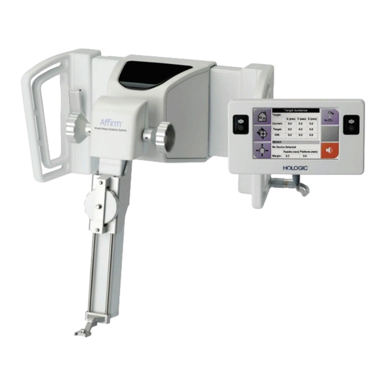
Affirm Breast Biopsy Guidance System User Guide Appendix A: System Specifications Appendix A System Specifications App endix A Affirm System Measurements Figure 74: Affirm Biopsy Guidance Module A. Height 37.1 cm (14.6 inches) B. Width 37.8 cm (14.9 inches) C. Depth 35.6 cm (14 inches) -
Page 98: Lateral Arm Measurements
Affirm Breast Biopsy Guidance System User Guide Appendix A: System Specifications Lateral Arm Measurements Figure 75: Lateral Arm A. Height 24.4 cm (9.6 inches) B. Width (Biopsy Device Mount 53.0 cm (20.9 inches) and Needle Guide extended toward Lateral Arm Mount) C. -
Page 99: Biopsy Guidance Module
Affirm Breast Biopsy Guidance System User Guide Appendix A: System Specifications Biopsy Guidance Module Accuracy of Biopsy Guidance maximum deviation: 1 mm in either direction of target coordinate Module Combined Accuracy of Biopsy maximum deviation: 2 mm in either direction of target coordinate... -
Page 101: Appendix B: System Messages And Alerts
Affirm Breast Biopsy Guidance System User Guide Appendix B: System Messages and Alerts Appendix B System Messages and Alerts App endix B Audible Alerts Table 11: Affirm System Audible Alerts Activity Frequency Duration Repeats? At Power Up: 250 ms Any Needle position within the... - Page 102 If the message continues to display, contact Technical Support. Selftest Error Disconnect the Affirm Biopsy Guidance Module cable from the imaging system. Reconnect the Affirm Biopsy Guidance Module cable to the imaging system. If the message continues to display, contact Technical Support. Stuck Switch Fault Disconnect the Biopsy Control Module cable from the Biopsy Guidance Module.
-
Page 103: Acquisition Workstation Messages
Icon Message User Action Affirm cable is not connected Connect the Affirm system cable to the side of the Gantry. Affirm is not locked Lock each side of the Affirm system. BCM cable is not connected Connect the Biopsy Control Module cable to the side of the Affirm system. -
Page 105: Appendix C: Cnr Correction For Biopsy
Affirm Breast Biopsy Guidance System User Guide Appendix C: CNR Correction for Biopsy Appendix C CNR Correction for Biopsy App endix C CNR Correction for Stereotactic 2D Biopsy Note System default setting is AEC Table 0 for imaging under stereotactic 2D biopsy mode. -
Page 107: Appendix D: Forms
Affirm Breast Biopsy Guidance System User Guide Appendix D: Forms Appendix D Forms App endix D QAS Test Checklist Date Tech X Diff Y Diff Z Diff Pass/Fail MAN-06411-002 Revision 003 Page 95... -
Page 108: Qas Test Checklist For The Lateral Arm
Affirm Breast Biopsy Guidance System User Guide Appendix D: Forms QAS Test Checklist for the Lateral Arm Date Tech X Diff Y Diff Z Diff Lat X Diff Lat X Diff Pass/Fail Left Right Page 96 MAN-06411-002 Revision 003... -
Page 109: Appendix E: Ancillary Parts For Biopsy
Affirm Breast Biopsy Guidance System User Guide Appendix E: Ancillary Parts for Biopsy Appendix E Ancillary Parts for Biopsy App endix E Hologic Factory-Verified Biopsy Devices Table 14: Hologic Factory-Verified Biopsy Devices Manufacturer Description Model Hologic Affirm QAS Needle ASY-03949... -
Page 110: Wire Localization Needle Guides
The following table provides the part numbers of the wire localization (loc) needle guides. These items can be ordered by either calling 1-877-371-4372 and following the prompts for parts or sending an email to Parts@hologic.com. Outside of the USA, contact your local Hologic dealer. -
Page 111: Glossary Of Terms
Affirm Breast Biopsy Guidance System User Guide Glossary of Terms Safety Margins Glossary of Terms The minimum space allowed between the biopsy device needle tip that is installed and components Affirm System of the system (for example, image receptor or... -
Page 113: Index
Affirm Breast Biopsy Guidance System User Guide Index Index home screen • 41 host connection verification • 36 adjustment information biopsy control module position • 18 general • 7 bracket height • 18 installation control module position • 18 biopsy control module • 17 Affirm system storage •... - Page 114 Affirm Breast Biopsy Guidance System User Guide Index lateral arm • 24 needle guides, lateral arm • 28 X-Stop • 34 requirements training • 2 skills needed • 1 specifications • 85 stereo biopsy mode C-arm rotation • 55 stereo views • 51 stereotactic lesion targeting •...
- Page 116 Affirm Breast Biopsy Guidance System User Guide Index Brazilian Contact Refer to the corporate website for more facilities worldwide. www.hologic.com Page 104 MAN-06411-002 Revision 003...
Need help?
Do you have a question about the Affirm and is the answer not in the manual?
Questions and answers