Hologic selenia dimensions User Manual
Hide thumbs
Also See for selenia dimensions:
- User manual (168 pages) ,
- Instructions for use manual (146 pages) ,
- Site planning & installation manual (56 pages)
Table of Contents
Advertisement
Quick Links
Advertisement
Table of Contents

Related Manuals for Hologic selenia dimensions


Summary of Contents for Hologic selenia dimensions
-
Page 3: Technical Support
© Copyright Hologic 2010. All rights reserved. Printed in USA. This manual was originally written in English. Hologic and the Hologic Logo are trademarks or registered trademarks of Hologic, Inc. Other trademarks registered or used by Hologic and its divisions and subsidiaries in the United States and other countries include: Dimensions, DSM, FAST Paddle, HTC, MIMS plus, M-IV, MultiCare, SecurView, Selenia, Smart Paddle, SmartWindow, StereoLoc, and TechMate. -
Page 5: Table Of Contents
4.0 Skills Needed for System Use ......................xiii 5.0 Training Requirements ......................... xiv 6.0 Quality Control Requirements ......................xiv 7.0 Hologic Cybersecurity Statement ......................xiv 8.0 Warnings, Cautions, and Notes ......................xiv 9.0 Terms and Definitions .......................... xv 10.0 International Symbols ........................xvi 11.0 Document Standards ......................... - Page 6 User Manual Table of Contents 4.0 How to Turn On the Selenia Dimensions ..................... 15 4.1 Preparation ............................ 15 4.2 Startup ............................15 4.3 Log In ............................16 5.0 Perform the Functional Tests ........................ 17 6.0 How to Turn Off the System ......................... 23 7.0 How to Remove All Power from the Acquisition Workstation ..............
- Page 7 User Manual Table of Contents Chapter 5—How to Use the Accessories 1.0 Introduction ............................47 2.0 How to Install Accessories on the C-arm ....................47 3.0 The Patient Face Shields ........................48 3.1 How to Install or Remove the Conventional Face Shield ..............48 3.2 How to Install or Remove the Retractable Face Shield ..............
- Page 8 User Manual Table of Contents Appendix A—Specifications 1.0 Product Measurements ......................... 73 1.1 Tubestand (Gantry with C-arm) ...................... 73 1.2 Acquisition Workstation ........................ 74 2.0 Operation and Storage Environment ....................75 2.1 General Conditions for Operation ....................75 2.2 Storage Environment ........................75 3.0 Acquisition Workstation Technical Information ...................
-
Page 9: List Of Figures
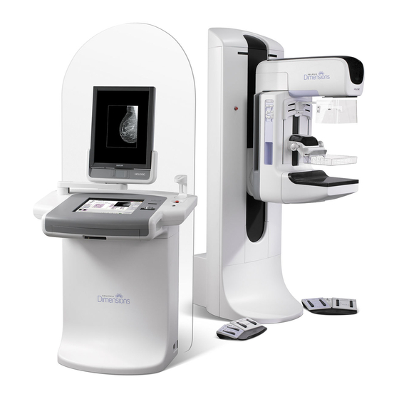
User Manual List of Figures List of Figures Figure 1-1: Selenia Dimensions ........................1 Figure 1-2: Label Locations........................... 8 Figure 2-1: System Power Controls ....................... 9 Figure 2-2: Acquisition Workstation Controls and Displays ................ 10 Figure 2-3: Tubestand Controls and Indicators.................... 12 Figure 2-4: C-arm Controls ......................... - Page 10 User Manual List of Figures P/N MAN-01964 Revision 001 DRAFT Preview copy—Generated 7/9/2010...
-
Page 11: List Of Tables
User Manual List of Tables List of Tables Table 2-1: C-arm Functional Tests ....................... 17 Table 3-1: Taskbar Menus ........................... 39 Table 8-1: Admin Screen Functions ......................69 Table 8-2: Radiologic Technologist Manager—Service Tools Functions............71 Table A-1: mA Setting as a Function of kV....................78 Table B-1: System Messages ........................ - Page 12 User Manual List of Tables P/N MAN-01964 Revision 001 DRAFT Preview copy—Generated 7/9/2010...
-
Page 13: Preface
Digital Breast Tomosynthesis System generates digital mammographic images that can be used for screening and diagnosis of breast cancer. The Selenia Dimensions system is intended for use in the same clinical applications as Full Field Digital Mammography systems for screening mammograms. Specifically, the Selenia Dimensions system can be used to acquire two-dimensional full field digital mammograms and three-dimensional tomosynthesis mammograms. -
Page 14: Training Requirements
Hologic™ does not accept the responsibility for injury or damage from wrong system operation. Make sure that you receive training on the Selenia Dimensions before use on patients. Hologic training programs address MQSA training regulations for any Technologist or Physician. -
Page 15: Terms And Definitions
Softcopy workstation for diagnoses from digital images. DICOM Digital Imaging and Communications in Medicine Gantry A part of the Selenia Dimensions that has the Detector, Generator and x-ray Source, Positioning/Compression, Power Distribution, and Accessories Subsystems. Grid Element within the Digital Image Receptor that reduces scatter radiation during the exposure. -
Page 16: 10.0 International Symbols
User Manual Preface International Symbols 10.0 International Symbols This section describes the International Symbols on the Selenia Dimensions. Connection for a conductor different from the Protective Potential Equalization Earth for a direct connection between two or more pieces terminal of electrical equipment. -
Page 17: Chapter 1-General Information
Always follow all the instructions in this manual. Hologic does not accept the responsibility for injury or damage from wrong system operation. Hologic can arrange for training at your facility. The Selenia Dimensions has protective devices, but the Technologist must understand how to safely use the system. - Page 18 Note… Hologic does not provide the Gantry power cable for some countries. If the power cable is not provided, the installed cable must meet the following requirements and all local codes that apply: 3 conductor, 8 AWG (10 mm ) copper not more than 25 feet (7.62 meters) in length.
-
Page 19: Patient Safety
User Manual Chapter 1—General Information Safety Information Patient Safety After power failure, remove the patient from the system WARNING! before you apply power. To keep the isolation quality for the system, attach only WARNING! approved accessories or options to the system. Only the authorized personnel can make changes to the connections. -
Page 20: Radiation Safety
User Manual Chapter 1—General Information Safety Information Warning: You increase the patient dose to high levels if you increase the AEC exposure adjustment setting. You increase the image noise or decrease image quality if you decrease the AEC exposure adjustment setting. Warning: Put both footswitches away from the patient and C-arm area to prevent any accidental footswitch use. -
Page 21: Data Loss
User Manual Chapter 1—General Information Safety Information Data Loss Warning: Do not move the C-arm while the system retrieves the image. Caution Never turn off the Acquisition Workstation Circuit Breaker except in emergency. The circuit breaker can turn off the Uninterruptible Power Supply (UPS) and risk data loss. -
Page 22: Interlocks
User Manual Chapter 1—General Information Safety Information Interlocks The Selenia Dimensions has safety interlocks: • The C-arm vertical drive and rotation is disabled when 45 Newtons (10 pounds) or greater of compression force is displayed. • If the x-ray button is released before the end of the exposure, the exposure stops and an alarm message appears. -
Page 23: Compliance
• The network and communication equipment must be installed to meet IEC Standards. The complete system (network and communications equipment and Selenia Dimensions Mammography System) must be in compliance with IEC 60601-1 and IEC 60601-1-1. Compliance Statements The manufacturer states this device is made to meet the following requirements: •... -
Page 24: Label Locations
User Manual Chapter 1—General Information Label Locations Label Locations Figure 1-2: Label Locations P/N MAN-01964 Revision 001 DRAFT Preview copy—Generated 7/9/2010... -
Page 25: Chapter 2-System Controls And Indicators
User Manual Chapter 2—System Controls and Indicators System Power Controls Chapter 2—System Controls and Indicators System Power Controls Figure 2-1: System Power Controls Legend for Figure 2-1 Gantry Power Circuit Breaker Emergency Off Switch (two on the Gantry, one on the Acquisition Workstation) Acquisition Workstation Power Circuit Breaker Computer Power Button UPS Power Button... -
Page 26: Acquisition Workstation Controls And Display
User Manual Chapter 2—System Controls and Indicators Acquisition Workstation Controls and Display Acquisition Workstation Controls and Display Figure 2-2: Acquisition Workstation Controls and Displays Legend for Figure 2-2 Trackball Scroll Wheel Compression Release Emergency Off Switch Fingerprint Reader X-ray Button (one on each side) Touchscreen Display Keyboard (in drawer) CD/DVD Drive... -
Page 27: Keyboard
User Manual Chapter 2—System Controls and Indicators Acquisition Workstation Controls and Display Keyboard Use the keyboard in the front drawer of the Acquisition Workstation for data entry. Bar Code Reader Use this device for data entry from bar codes for patient or procedure records. Acquisition Workstation Touchscreen Display Use the Touchscreen or trackball to select items. -
Page 28: Tubestand Controls And Indicators
User Manual Chapter 2—System Controls and Indicators Tubestand Controls and Indicators Tubestand Controls and Indicators Legend for Figure 2-3 1. The Rotation Angle Displays (each side) 2. The C-arm Controls (each side) 3. The Compression Device 4. The Patient Handles (each side) 5. -
Page 29: C-Arm Controls
User Manual Chapter 2—System Controls and Indicators Tubestand Controls and Indicators C-arm Controls The C-arm Controls provide the Collimator and C-arm functions. See Section 5.0, page 17. Figure 2-4: C-arm Controls Compression Device Controls and Displays Legend for Figure 2-5 Manual Compression Handwheels Paddle Shift Buttons AEC Buttons... -
Page 30: Tubehead Display
User Manual Chapter 2—System Controls and Indicators Tubestand Controls and Indicators Tubehead Display The Tubehead Display shows: • • Filter Type • Collimator Setting • Paddle Position c m R h S I D : 7 0 x 2 9 C o ll : 2 4 Figure 2-7: Tubehead Display Dual Function Footswitches... -
Page 31: How To Turn On The Selenia Dimensions
User Manual Chapter 2—System Controls and Indicators How to Turn On the Selenia Dimensions How to Turn On the Selenia Dimensions Preparation 1. Reset all three Emergency Off switches. 2. Make sure that both system circuit breakers are in the On position. -
Page 32: Log In
User Manual Chapter 2—System Controls and Indicators How to Turn On the Selenia Dimensions Log In Figure 2-10: How to Log In When the user Log In screen displays, all Managers and Technologists show in the list of Operators. 1. To display the Service, Applications, and Physicists user names, select the Show All button. -
Page 33: Perform The Functional Tests
User Manual Chapter 2—System Controls and Indicators Perform the Functional Tests Perform the Functional Tests Legend for Figure 2-11 Compression Release (Future use) Light Field Lamp (Future use) Collimator Override Clockwise C-arm Rotation C-arm Up and Down Counterclockwise C-arm Rotation Compression Up 10. - Page 34 User Manual Chapter 2—System Controls and Indicators Perform the Functional Tests Table 2-1: C-arm Functional Tests Function Functional Test Compression Up Press a Compression Up button: • The Compression Device moves toward the top. • The Compression Up button does not release the Compression Brake.
- Page 35 User Manual Chapter 2—System Controls and Indicators Perform the Functional Tests Table 2-1: C-arm Functional Tests Function Functional Test C-arm Down Press the C-arm Down button: • The C-arm movement automatically stops when the button is released. • The C-arm movement automatically stops when the C-arm reaches the lower travel limit.
- Page 36 User Manual Chapter 2—System Controls and Indicators Perform the Functional Tests Table 2-1: C-arm Functional Tests Function Functional Test Counterclockwise C-arm Press the Counterclockwise C-arm Rotation to start Rotation counterclockwise C-arm rotation. Left Panel Right Panel Clockwise C-arm Rotation Press the Clockwise C-arm Rotation button to start clockwise C-arm rotation.
- Page 37 User Manual Chapter 2—System Controls and Indicators Perform the Functional Tests Table 2-1: C-arm Functional Tests Function Functional Test C-arm Rotation Switch Push the C-arm Rotation switch away from you to move the C-arm toward you. Pull the C-arm Rotation switch toward you to move the C-arm away.
- Page 38 User Manual Chapter 2—System Controls and Indicators Perform the Functional Tests Table 2-1: C-arm Functional Tests Function Functional Test Collimator Override The Collimator Override button changes the collimation through the different x-ray fields. Press the light field lamp button to show the x-ray field, then press the Collimator Override button to select an x-ray field.
-
Page 39: How To Turn Off The System
User Manual Chapter 2—System Controls and Indicators How to Turn Off the System Table 2-1: C-arm Functional Tests Function Functional Test Emergency Off Switches There are three Emergency Off switches, one on each side of the Gantry and one on the Acquisition Workstation. Press any of the Emergency Off switches to turn Off the Gantry. - Page 40 User Manual Chapter 2—System Controls and Indicators How to Remove All Power from the Acquisition Workstation P/N MAN-01964 Revision 001 DRAFT Preview copy—Generated 7/9/2010...
-
Page 41: Chapter 3-The User Interface
User Manual Chapter 3—The User Interface Select the Function to Perform Chapter 3—The User Interface Select the Function to Perform After you log in, the Select Function to Perform screen displays. Note… The Select Patient screen appears if you are not scheduled to perform any Quality Control tasks. -
Page 42: How To Perform The Quality Control Tasks
User Manual Chapter 3—The User Interface How to Perform the Quality Control Tasks How to Perform the Quality Control Tasks 1. Select a Quality Control task from the Select Function to Perform screen. 2. Select the Start button. 3. Follow the on-screen prompts to complete the procedure. Figure 3-2: An Example Gain Calibration Screen Note…... -
Page 43: How To Select A Patient
User Manual Chapter 3—The User Interface How to Select a Patient How to Select a Patient Figure 3-3: How to Select a Patient Eight tabs display at the top of the screen. These tabs are configurable. A user with the right permissions can delete tabs and create new tabs. -
Page 44: How To Add A New Patient
User Manual Chapter 3—The User Interface How to Select a Patient How to Add a New Patient 1. In the Select Patient screen, select the New button. 2. Enter new patient information and select a procedure. 3. Select the Open button. A screen for the new patient information appears. Figure 3-4: How to Add a New Patient How to Edit the Patient Information 1. -
Page 45: How To Use A Patient Filter
User Manual Chapter 3—The User Interface How to Select a Patient How to Use a Patient Filter When you select the Filter button in the Select Patient screen, the Patient Filter screen for the selected tab appears. See Figure 3-5. Figure 3-5: The Filter Tab in the Patient Filter Screen From the Filter and Column tabs, select the information that appears on the selected tab page of the Select a Patient screen. -
Page 46: How To Query The Worklist
User Manual Chapter 3—The User Interface How to Select a Patient How to Query the Worklist Use the Query Worklist feature to search for a patient or a list of patients. There are two methods to enter the query information: •... -
Page 47: The Procedure Screen
User Manual Chapter 3—The User Interface The Procedure Screen The Procedure Screen Select the Generator tab (at the top of the screen on the left side) to adjust the exposure techniques for the procedure. Select the options in the Tools tab (at the top of the screen on the left side) for image review (see Chapter 4, Section 2.0, page 42). -
Page 48: How To Use The Implant Present Button
User Manual Chapter 3—The User Interface The Procedure Screen 4.1.3 How to Use the AEC Sensor The AEC Sensor has seven manual positions and an automatic position. The manual positions start at the chest wall edge (position 1) and reach to the nipple edge (position 7). -
Page 49: How To Add Or Remove A View
User Manual Chapter 3—The User Interface The Procedure Screen How to Add or Remove a View 1. To add a view, select the Add View button to display the Add View screen. View Modifiers ID = Implant Displaced RL = Rolled Lateral RM = Rolled Medial RI = Rolled Inferior RS = Rolled Superior... -
Page 50: How To Add A Procedure
User Manual Chapter 3—The User Interface The Procedure Screen How to Add a Procedure 1. To add another procedure, select the Add Procedure button on the Procedure screen to display the Add Procedure dialog box. Figure 3-8: The Add Procedure Dialog Box 2. -
Page 51: How To Close A Procedure
User Manual Chapter 3—The User Interface How to Access Image Review Features How to Close a Procedure Select the Close Patient button. If you acquired images, a Close Procedure dialog box displays. Select one of the following options: • Close Procedure Complete Closes the procedure and puts the procedure in the Complete tab. -
Page 52: How To Use The On-Demand Outputs
User Manual Chapter 3—The User Interface How to Use the On-Demand Outputs To edit an Output Set: 1. Access the Admin screen. 2. Select the Manage Output Groups button. 3. Select the Edit button, then make the changes. 4. Select the Save button. When the Update Successful message displays, select OK. How to Use the On-Demand Outputs You can manually Archive, Print, or Export an image until the procedure is closed. -
Page 53: How To Print
User Manual Chapter 3—The User Interface How to Use the On-Demand Outputs How to Print 7.2.1 The Print Screen Figure 3-10: The Print Screen Legend for Figure 3-10 1. Mirrors the image. 2. Selects the film format (number of tiles). 3. -
Page 54: How To Export
User Manual Chapter 3—The User Interface How to Use the Paddle Shift Feature 7.2.2 How to Use the Print Screen 1. From the Procedure screen, select the Print button. The Print Screen displays. Refer to Figure 3-10 to prepare your print information. 2. -
Page 55: About The Taskbar
User Manual Chapter 3—The User Interface About the Taskbar About the Taskbar The taskbar at the bottom of the screen displays additional icons, which you can select to access information or perform system tasks. Table 3-1: Taskbar Menus Description Menu Information Icon Select the Information icon to display a menu. - Page 56 User Manual Chapter 3—The User Interface About the Taskbar P/N MAN-01964 Revision 001 DRAFT Preview copy—Generated 7/9/2010...
-
Page 57: Chapter 4-The Images
User Manual Chapter 4—The Images Introduction Chapter 4—The Images Introduction After you make an exposure, the acquired image displays on the Preview screen. Review the image and add the annotations, then Accept, Reject, or Pend the image. A thumbnail image appears in the Case Study area of the screen. -
Page 58: How To Review The Images
User Manual Chapter 4—The Images How to Review the Images How to Review the Images Figure 4-2: The Tools Tab in the Procedure Screen Select any thumbnail image to display that image in the Preview screen. The thumbnail image is marked if the image is not accepted. Figure 4-3: Marked Images in a Procedure P/N MAN-01964 Revision 001... -
Page 59: The Image Review Tools Tab
User Manual Chapter 4—The Images How to Review the Images The Image Review Tools Tab The Tools tab in the Procedure screen provides the image review tools. A checkmark appears on the button of an active tool. Figure 4-4: Image Review Tools Legend for Figure 4-4 The Zoom tool magnifies a section of the image. -
Page 60: Other Image Review Tools
User Manual Chapter 4—The Images How to Review the Images Other Image Review Tools 2.2.1 The Image Review Tabs Each tab provides additional image review functions. Figure 4-5: Image Review Tabs • Cine: Show a series of images as a movie (Tomosynthesis option). •... -
Page 61: How To Correct And Reprocess Implant Images
User Manual Chapter 4—The Images Send the Images to the Output Devices 2.2.3 Display Modes (Tomosynthesis option) Use the CONV, PRJ, and REC buttons to select the type of view to display in the Preview Screen. You can change between CONV (conventional), PRJ (projections), and REC (reconstruction) to display the combination images. - Page 62 User Manual Chapter 4—The Images Send the Images to the Output Devices P/N MAN-01964 Revision 001 DRAFT Preview copy—Generated 7/9/2010...
-
Page 63: Chapter 5-How To Use The Accessories
Introduction Chapter 5—How to Use the Accessories Introduction The Selenia Dimensions can perform screening or diagnostic applications with specified accessories. This chapter describes how to use all possible system accessories. Your accessories depend on your system configuration. How to Install Accessories on the C-arm The Retractable Face Shield, Magnification Stand, and Localization Crosshairs are installed in slots on the C-arm. -
Page 64: The Patient Face Shields
User Manual Chapter 5—How to Use the Accessories The Patient Face Shields The Patient Face Shields The Face Shield keeps the head and face of the patient away from the x-ray field during the examination. Inspect the shield each day before use. Warning: The Face Shield must be attached for all exposures except magnification case studies. -
Page 65: How To Install Or Remove The Retractable Face Shield
User Manual Chapter 5—How to Use the Accessories The Patient Face Shields How to Install or Remove the Retractable Face Shield To install the Retractable Face Shield, see Figure 5-4, page 50: 1. Completely extend the Face Shield to the outer position. 2. -
Page 66: How To Use The Retractable Face Shield
User Manual Chapter 5—How to Use the Accessories The Patient Face Shields How to Use the Retractable Face Shield 1. Always completely extend the Face Shield before an exposure. 2. To extend the Face Shield, pull the shield away from the C-arm until the device latches in the outer position. -
Page 67: Compression Paddles
User Manual Chapter 5—How to Use the Accessories Compression Paddles Compression Paddles The system can identify each paddle and automatically adjust the collimator. Routine Screening Paddles 18 x 24 cm Frameless 24 x 29 cm Frameless Small Breast Frameless Screening Paddle Screening Paddle Paddle Contact and Spot Compression Paddles... -
Page 68: Localization Paddles
User Manual Chapter 5—How to Use the Accessories Compression Paddles Localization Paddles 10 cm Rectangular Opening 15 cm Rectangular Opening Localization Paddle Localization Paddle 10 cm Perforated 15 cm Perforated Localization Paddle Localization Paddle Magnification Paddles 7.5 cm Spot Magnification 10 cm Magnification Paddle Paddle... -
Page 69: How To Install Or Remove A Compression Paddle
User Manual Chapter 5—How to Use the Accessories Compression Paddles How to Install or Remove a Compression Paddle See Figure 5-6 to install a Compression Paddle: 1. Hold the front of the paddle with one hand in front of the Compression Device. 2. -
Page 70: Fast Compression Mode
User Manual Chapter 5—How to Use the Accessories Compression Paddles FAST Compression Mode 4.8.1 How the FAST Compression Mode Works The Fully Automatic Self-adjusting Tilt (FAST) Compression Mode is for use when the composition of the breast tissue does not allow uniform compression across the complete breast with a flat compression paddle. -
Page 71: Magnification Stand
Magnification Stand Magnification Stand The Selenia Dimensions Magnification Stand has a breast platform and an abdominal shield. When the Magnification Stand is installed, the HTC grid automatically retracts and the x-ray exposure techniques are set to the Magnification default values. When the platform is installed, only use the Magnification paddles (see Section 4.4, page 52). -
Page 72: Crosshair Devices
User Manual Chapter 5—How to Use the Accessories Crosshair Devices Crosshair Devices How to Install and Remove the Localization Crosshair Device Figure 5-10: How to Attach the Localization Crosshair Device 6.1.1 To install the Localization Crosshair Device 1. Remove the face shield (see Section 3.0, page 48). 2. -
Page 73: How To Install And Remove The Magnification Crosshair Device
User Manual Chapter 5—How to Use the Accessories Crosshair Devices How to Install and Remove the Magnification Crosshair Device Figure 5-11: How to Install and Remove the Magnification Crosshair Device 6.3.1 To install the Magnification Crosshair Device 1. Remove the face shield (see Section 3.1, page 48). 2. - Page 74 User Manual Chapter 5—How to Use the Accessories Crosshair Devices P/N MAN-01964 Revision 001 DRAFT Preview copy—Generated 7/9/2010...
-
Page 75: Chapter 6-Clinical Procedures
User Manual Chapter 6—Clinical Procedures Standard Workflow Chapter 6—Clinical Procedures Warning: The C-arm movement has drive motors. Warning: Keep the hands of the patient away from all buttons and switches at all times. Warning: Put both footswitches away from the patient and C-arm area to prevent any accidental footswitch use. -
Page 76: Example Screening Procedure
User Manual Chapter 6—Clinical Procedures Example Screening Procedure Example Screening Procedure Figure 6-1: Screening Example, Conventional Procedure How to Position the Patient 1. Lift or lower the breast platform for the patient. 2. Move the tubehead to the projection angle. 3. -
Page 77: How To Acquire The Exposure
User Manual Chapter 6—Clinical Procedures Example Screening Procedure How to Acquire the Exposure 1. Confirm that all exposure factors are set correctly. 2. If the system does not display Ready in 30 seconds, verify that the accessories are correctly installed and the paddle is locked into position. When the generator status displays Ready, the system is ready for exposure. - Page 78 User Manual Chapter 6—Clinical Procedures Example Screening Procedure P/N MAN-01964 Revision 001 DRAFT Preview copy—Generated 7/9/2010...
-
Page 79: Chapter 7-Maintenance And Cleaning
Use a lint-free cloth or pad and apply a diluted dishwashing liquid. Caution The fluid must not flow or run. If more than soap and water is required, Hologic recommends any one of the following: • 10% chlorine bleach and water with one part commercially available chlorine bleach (normally 5.25% chlorine and 94.75% water) and nine parts water... -
Page 80: To Prevent Possible Injury Or Equipment Damage
User Manual Chapter 7—Maintenance and Cleaning General Information To prevent Possible Injury or Equipment Damage Never use a corrosive solvent or abrasive detergents or polishes. Select a cleaning agent which will not damage plastics, aluminum, or carbon fiber. • Do not use a strong detergent, abrasive cleaner, high alcohol concentration, or methanol at any concentration. -
Page 81: Acquisition Workstation
How to Clean the Keyboard Clean the key surfaces with a CRT wipe. If necessary, clean the keyboard with a vacuum. If liquids enter the keyboard, call the Hologic Technical Support for a replacement. How to Clean the Fingerprint Reader... - Page 82 User Manual Chapter 7—Maintenance and Cleaning Acquisition Workstation P/N MAN-01964 Revision 001 DRAFT Preview copy—Generated 7/9/2010...
-
Page 83: Chapter 8-System Administration Interface
User Manual Chapter 8—System Administration Interface How to Use the Admin Screen Chapter 8—System Administration Interface How to Use the Admin Screen This section describes the functions available in the Admin screen. To access all functions in this screen, log In to the system as a user with the administrator, manager, or service permissions. -
Page 84: Figure 8-1: The Admin Screen
User Manual Chapter 8—System Administration Interface How to Use the Admin Screen Refer to Table 8-1, page 69 for descriptions of the Admin screen functions. Figure 8-1: The Admin Screen P/N MAN-01964 Revision 001 DRAFT Preview copy—Generated 7/9/2010... -
Page 85: Table 8-1: Admin Screen Functions
User Manual Chapter 8—System Administration Interface How to Use the Admin Screen Table 8-1: Admin Screen Functions Section Screen Function Description Operators Manage Operators Add, delete or change Operator information. My Settings Change the information for the current Operator. Procedures Procedure Editor Add or Edit the procedures, or change the view order for each user. -
Page 86: How To Use The System Tools
The Radiologic Technologist Managers and users with Service permissions can access the Service Tools function. The Service Tools function contains the configuration information about Selenia Dimensions. To access the Service Tools function: 1. Log on as the Tech Manager or Service. -
Page 87: Table 8-2: Radiologic Technologist Manager-Service Tools Functions
User Manual Chapter 8—System Administration Interface How to Use the System Tools Table 8-2: Radiologic Technologist Manager—Service Tools Functions Section Screen Functions Description Getting Started About The introduction to the service tool. List of common questions. Glossary List of terms and descriptions. Platform List of directories, software version numbers, and system software statistics. - Page 88 User Manual Chapter 8—System Administration Interface How to Use the System Tools P/N MAN-01964 Revision 001 DRAFT Preview copy—Generated 7/9/2010...
-
Page 89: Appendix A-Specifications
User Manual Appendix A—Specifications Product Measurements Appendix A—Specifications Product Measurements Tubestand (Gantry with C-arm) Figure A-1: Tubestand Dimensions 223 cm (87.8 inches) Height 66 cm (26 inches) Width 138 cm (54.25 inches) Depth Weight Maximum of 400 kg (882 pounds) P/N MAN-01964 Revision 001 Preview copy—Generated 7/9/2010... -
Page 90: Acquisition Workstation
User Manual Appendix A—Specifications Product Measurements Acquisition Workstation 207 cm (81.5 in.) 92.7 cm (36.5 in.) 58.5 cm (23 in.) Figure A-2: Acquisition Workstation Dimensions 207 cm (81.5 inches) Height 92.7 cm (36.5 inches) Width 58.5 cm (23 inches) Depth 154 kg (340 pounds) Weight P/N MAN-01964... -
Page 91: Operation And Storage Environment
User Manual Appendix A—Specifications Operation and Storage Environment Operation and Storage Environment General Conditions for Operation Temperature Range 20 °C to 30 °C 20% to 80% Without condensing moisture Relative Humidity Range Storage Environment 2.2.1 Gantry Temperature Range –10 °C to 40 °C Relative Humidity Range 0% to 95% Without condensing moisture (Put in a package for storage in a... -
Page 92: Electrical Input
User Manual Appendix A—Specifications Electrical Input Electrical Input Tubestand Mains Voltage 200 to 240 VAC ±10% Maximum line impedance not to exceed 0.20 ohms for Mains Impedance 208/220/230/240 VAC, 0.16 ohms for 200 VAC 50/60 Hz ±5% Mains Frequency Average Current over 24 Hours <... -
Page 93: Compression
User Manual Appendix A—Specifications Tubestand Technical Information Compression Maximum of 300 N (67.4 pounds) Manual Compression Force Functions in three operating modes, Pre-compression, Full- Motorized Compression Range, Dual Compression, user selectable through software 15 pounds to 30 pounds (67 to 134 N), motorized Pre-Compression Force 20 pounds to 40 pounds (89 to 178 N), motorized Full Range Compression Force... -
Page 94: X-Ray Beam Filtration And Output
User Manual Appendix A—Specifications Tubestand Technical Information X-ray Beam Filtration and Output Five-position filter wheel: Filtration Position 1: Rhodium, 0.050 mm ±10% Position 2: Aluminum, 0.70 mm ±10% (Tomosynthesis option) Position 3: Silver, 0.050 mm ±10% Position 4: Lead (provided for servicing) Position 5: Lead (provided for servicing) 5.4.1 kV/mA Range... -
Page 95: X-Ray Collimation
User Manual Appendix A—Specifications Imaging System Technical Information X-ray Collimation 7.0 cm x 8.5 cm Collimation Fields 10 cm x 10 cm 15 cm x 15 cm 18 cm x 24 cm 18 cm x 29 cm (Tomosynthesis option) 24 cm x 29 cm Light Field Indication Light Field to X-Ray Congruency Within 2% of SID... - Page 96 User Manual Appendix A—Specifications Imaging System Technical Information P/N MAN-01964 Revision 001 DRAFT Preview copy—Generated 7/9/2010...
-
Page 97: Appendix B-The System Messages And Alert Messages
(for example to call Hologic Technical support.) This chapter describes the message categories and your actions to return the system to normal operation. If errors repeat, contact Hologic Technical Support. -
Page 98: System Messages
User Manual Appendix B—The System Messages and Alert Messages Types of Messages and Alert messages System Messages When the following system messages appear, perform the action indicated to clear the message and allow the next exposure. Table B-1: System Messages Icon Message User Action... -
Page 99: List Of Addenda
User Manual List of Addenda List of Addenda Write the title of all Addenda which are supplied for this manual, with their part number and revision. Add all the Addenda to the manual after this record page. Title Part Number Revision P/N MAN-01964 Revision 001... - Page 100 User Manual List of Addenda P/N MAN-01964 Revision 001 DRAFT Preview copy—Generated 7/9/2010...
-
Page 101: Index
User Manual Index Index close patient 35 accept images 61 procedure 35 accept rejected images 61 procedure with MPPS 35 accessories collimator compression paddles 51 override 22 crosshair devices 56 programmed to paddle 51 face shield 48 programmed to paddle position 22 install on C-arm 47 comments tab 44 Magnification Stand 55... - Page 102 12 magnification paddles 52 generator tab, set techniques 31 Magnification Stand 55 glossary xv install and remove 55 maintenance Acquisition Workstation 65 Hologic technical support 63 general 63 manage alarms 39 notices 39 images output groups 35 accept 61...
- Page 103 User Manual Index open patient procedure 27 Magnification Stand 55 output devices Tomo face shield 49 manage output sets 39 view 33 output set 45 requirements taskbar icons 39 quality control xiv output groups, manage 45 training xiv output sets, select 35 review outputs, on-demand 36 images 42...
- Page 104 User Manual Index taskbar 39 terms and definitions xv tomo face shield install 49 use 50 tools, image review 43 Touchscreen 11 clean 65 training requirements xiv tubehead, display 14 tubestand controls and indicators 12 turn off system 23 turn on system 15 Log In 16 preparation 15 startup 15...
Need help?
Do you have a question about the selenia dimensions and is the answer not in the manual?
Questions and answers