Table of Contents
Advertisement
Advertisement
Chapters
Table of Contents

Related Manuals for Hologic 3Dimensions


Summary of Contents for Hologic 3Dimensions
- Page 3 3Dimensions ™ Digital Mammography System Digital Tomosynthesis System User Guide For Software Version 2.0 Part Number MAN-05085-002 Revision 002 May 2018...
- Page 4 Hologic, 3Dimensions, 3D, 3D Mammography, Affirm, C-View, Dimensions, FAST Paddle, Genius, I-View, Selenia, SmartCurve, and associated logos are trademarks and/or registered trademarks of Hologic, Inc., and/or its subsidiaries in the United States and/or other countries. All other trademarks, registered trademarks, and product names are the property of their respective owners.
-
Page 5: Table Of Contents
1.11 Where to Find Technical Description Information ..................... 7 1.12 Warranty Statement ..............................8 1.13 Technical Support ..............................8 1.14 Product Complaints ..............................8 1.15 Hologic Cybersecurity Statement ......................... 8 1.16 Symbols ..................................9 1.17 Descriptions of Warnings, Cautions, and Notes ....................10 1.18 Document Conventions ............................10 2: General Information __________________________________________________________11 System Overview .............................. - Page 6 3Dimensions System User Guide Table of Contents 3: System Controls and Indicators ________________________________________________23 System Power Controls ............................23 Tubestand Controls and Indicators ........................24 3.2.1 Tubehead Display ........................... 25 3.2.2 Compression Device Controls and Display ..................25 3.2.3 C-Arm Control Panels ..........................26 3.2.4...
- Page 7 3Dimensions System User Guide Table of Contents 5.4.7 Retrieve ..............................61 5.4.8 Close a Patient ............................62 How to Access the Image Review Features ...................... 62 Output Groups ..............................63 5.6.1 Select an Output Group ......................... 63 5.6.2 Add or Edit an Output Group ......................63 5.6.3...
- Page 8 3Dimensions System User Guide Table of Contents 7.3.4 Localization Paddles ..........................90 7.3.5 Large Ultrasound Paddle ........................90 7.3.6 How to Install and Remove a Compression Paddle ................91 7.3.7 Paddle Maintenance and Cleaning ...................... 91 7.3.8 Paddle Shift.............................. 92 7.3.9...
- Page 9 3Dimensions System User Guide Table of Contents 10.9 Enable and Set the Default Height ........................120 10.10 System Tools ................................ 122 10.10.1 System Tools for the Radiologic Technologist Manager ..............122 10.10.2 Remote Access to Image Reports ....................... 124 10.11 Archive Tool ................................ 126 Appendix A Specifications _____________________________________________________129 Product Measurements ............................
- Page 10 3Dimensions System User Guide Table of Contents Test the System after Travel ..........................148 C.6.1 Mobile System Controls and Functional Tests ................. 148 Quality Control Tests ............................148 Appendix D Dose Information _________________________________________________149 EUREF Dose Tables ............................149 Glossary of Terms _____________________________________________________________151...
-
Page 11: List Of Figures
3Dimensions System User Guide Table of Contents List of Figures Figure 1: 3Dimensions™ System ........................... 11 Figure 2: C-arm Overview .............................. 12 Figure 3: Emergency Off Switch Functionality ......................17 Figure 4: Label Locations ..............................21 Figure 5: System Power Controls ..........................23 Figure 6: Tubestand Controls and Indicators ...................... - Page 12 3Dimensions System User Guide Table of Contents Figure 43: Marked Images in a Procedure ........................72 Figure 44: Tools Tab (Tomosynthesis option shown) ....................74 Figure 45: Image Review Tools ............................75 Figure 46: Tools on the Notices Tab ..........................76 Figure 47: Exposure Index ..............................
- Page 13 3Dimensions System User Guide Table of Contents Figure 88: Create Image Report Parameters ......................125 Figure 89: Create Image Report ........................... 126 Figure 90: Archive Button ............................. 126 Figure 91: Multi Patient On Demand Archive Screen ....................127 Figure 92: Export Screen ............................... 128 Figure 93: Tubestand (Gantry with C-arm) Measurements ..................
-
Page 15: List Of Tables
3Dimensions System User Guide Table of Contents List of Tables Table 1: System Labels ..............................22 Table 2: Compression Tests ............................33 Table 3: C-arm Up and Down Movement ........................34 Table 4: C-arm Counterclockwise Rotation ........................36 Table 5: C-arm Clockwise Rotation ..........................37 Table 6: C-arm Rotation Switch ............................. -
Page 17: 1: Introduction
3Dimensions™ system is indicated to generate digital mammographic ® images that can be used for screening and diagnosis of breast cancer. The 3Dimensions (2D or 3D) system is intended for use in the same clinical applications as a 2D mammography system for screening mammograms. Specifically, the 3Dimensions system can be used to generate 2D digital mammograms and 3D mammograms. -
Page 18: Potential Adverse Effects Of Mammography Systems On Health
2D image or a 2D image generated from the 3D™ image set. The Genius™ exam is only available on a Hologic 3D Mammography™ system. ® Genius™ 3D Mammography™ is the brand name of a Hologic 3D Mammography™ exam, and may not be available in all markets. Page 2 MAN-05085-002 Revision 002... -
Page 19: More Information About Tomosynthesis
FDA website at http://www.accessdata.fda.gov/scripts/cdrh/cfdocs/cfpma/pma.cfm?id=P080003S001. A list of scientific publications about Breast Tomosynthesis is available from the Hologic website. The majority of the studies were done with the commercially released Hologic Selenia Dimensions Tomosynthesis system. See the publication at http://www.hologic.com/sites/default/files/Tomo-Bibliography-Rev-13.pdf. - Page 20 JAMA. 2014;311(24):2499-2507. doi:10.1001/jama.2014.6095 http://jama.jamanetwork.com/article.aspx?articleid=1883018 IMPORTANT: Hologic strongly recommends that users make themselves familiar with local or regional regulations. These regulations could impose restrictions on the different types of clinical use. Because the regulations could evolve and change over time, periodic review is recommended.
-
Page 21: About C-View And Intelligent 2D
3Dimensions System User Guide Chapter 1: Introduction About C-View and Intelligent 2D Note Intelligent 2D™ may not be available in all regions. Contact your sales representative for information 1.6.1 C-View and Intelligent 2D Software The C-View and Intelligent 2D software uses image data available from a breast tomosynthesis acquisition to generate one digital mammogram (2D) per breast tomosynthesis acquisition. -
Page 22: C-View And Intelligent 2D Theory Of Operation
Overview The C-View and Intelligent 2D software is an image processing application for post- processing the pixel data from tomosynthesis data, captured on a Hologic tomosynthesis imaging system, into a digital mammography (2D) image. The C-View or Intelligent 2D generated 2D image can be used in place of a digital mammogram (2D) as part of a screening study employing tomosynthesis. -
Page 23: Medical Physicist
Additionally, the user manual is a guide for directions on how to use the system. All users must make sure that they receive training on correct operation of the system before use on patients. Hologic does not accept the responsibility for injury or damage from incorrect system operation. Quality Control Requirements Facilities in the United States must use the Quality Control Manual to create a Quality Assurance and Quality Control program. -
Page 24: Warranty Statement
Hologic specifications or instructions, including Customer’s refusal to allow Hologic recommended Software upgrades; or (d) designated as supplied subject to a non-Hologic warranty or on a pre- release or “as-is” basis. 1.13 Technical Support Refer to the copyright page of this manual for contact information for product support. -
Page 25: Symbols
Potential Equalization terminal Protective Earth terminal "OFF" (power) "ON" (power) Discard electrical and electronic equipment separately from standard waste. Send decommissioned material to Hologic or contact your service representative. Warning Electricity Manufacturer Date of Manufacture This system transmits radio frequency (RF) energy (non-ionizing radiation) Caution—Radiation... -
Page 26: Descriptions Of Warnings, Cautions, And Notes
3Dimensions System User Guide Chapter 1: Introduction 1.17 Descriptions of Warnings, Cautions, and Notes Descriptions of Warnings, Cautions, and Notes used in this manual: WARNING! The procedures that you must follow accurately to prevent possible dangerous or fatal injury. Warning: The procedures that you must follow accurately to prevent injury. -
Page 27: 2: General Information
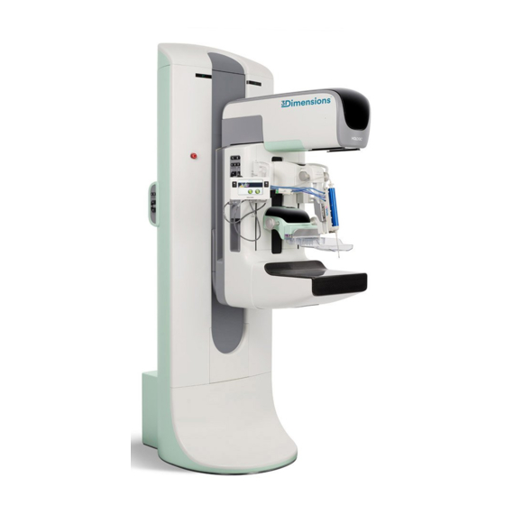
3Dimensions System User Guide Chapter 2: General Information Chapter 2 General Information System Overview Figure 1: 3Dimensions™ System Figure Legend 1. Tubestand (Gantry and C-arm) 2. Gantry 3. C-arm (Tube Arm and Compression Arm) 4. Universal Acquisition Workstation MAN-05085-002 Revision 002... -
Page 28: C-Arm Overview
3Dimensions System User Guide Chapter 2: General Information 2.1.1 C-Arm Overview Figure Legend 1. Tube Arm 2. Patient Face Shield 3. Compression Device 4. Image Receptor 5. Compression Arm 6. Patient Handle 7. C-arm Control Panel Figure 2: C-arm Overview... -
Page 29: Safety Information
Read and understand this manual before you use the system. Keep the manual available during the patient procedures. Always follow all the instructions in this manual. Hologic does not accept the responsibility for injury or damage from incorrect system operation. Hologic can schedule training at your facility. - Page 30 Manager, a diagnostic review workstation, or a hard copy printer) in the Patient Area. WARNING! Only trained Service Engineers authorized through Hologic can open any of the panels. This system contains lethal voltages. WARNING! The user must correct problems before the system is used. Contact an approved service representative for preventive maintenance.
- Page 31 3Dimensions System User Guide Chapter 2: General Information Warning: The disk drives installed in this system are a Class I Laser Product. Prevent direct exposure to the beam. Hidden laser radiation exists if the case to a disk drive is open.
- Page 32 3Dimensions System User Guide Chapter 2: General Information Warning: This system can be dangerous to the patient and the user. Always follow the safety precautions for x-ray exposures. Warning: For exposures except magnification case studies, always use the Face Shield.
-
Page 33: Emergency Off Switches
Note: Hologic does not supply the Gantry power cable for some countries. If the power cable is not supplied, the installed cable must meet the following requirements and all local codes that apply: 3 conductor, 8 AWG (10 mm ) copper not more than 25 feet (7.62... -
Page 34: Interlocks
Caution: The use of unauthorized accessories and cables can result in increased emissions or decreased immunity. To keep the isolation quality for the system, attach only approved Hologic accessories or options to the system. Page 18 MAN-05085-002 Revision 002 DRAFT... - Page 35 Caution: Changes or modifications not expressly approved by Hologic could void your authority to operate the equipment. Caution: This equipment has been tested and found to comply with the limits for a Class A digital device, pursuant to part 15 of the FCC Rules.
-
Page 36: Compliance Statements
3Dimensions System User Guide Chapter 2: General Information 2.6.2 Compliance Statements The manufacturer states this device is made to meet the following requirements: Medical – Applied electromagnetic radiation equipment as to electrical shock, fire and mechanical hazards only in accordance with ANSI/AAMI ES60601-1 (2005) and CAN/CSA-C22.2 No. -
Page 37: Label Locations
3Dimensions System User Guide Chapter 2: General Information Label Locations Figure 4: Label Locations MAN-05085-002 Revision 002 Page 21 DRAFT Preview Copy-Generated May 30, 2018... -
Page 38: Table 1: System Labels
3Dimensions System User Guide Chapter 2: General Information Table 1: System Labels Serialized Device System Model Electrical Shock Warning Potential Equalization Terminal Tomographic Mammography Detector Wheelchair Warning for Footswitch Gantry Nameplate Emergency Stop Switch X-ray Device Warning Vendor-supplied X-ray Tube Serial... -
Page 39: 3: System Controls And Indicators
3Dimensions System User Guide Chapter 3: System Controls and Indicators Chapter 3 System Controls and Indicators System Power Controls Figure 5: System Power Controls Figure Legend 1. Gantry Power Circuit Breaker 2. Emergency Off Switch (two on the Gantry, one on the Acquisition Workstation) 3. -
Page 40: Tubestand Controls And Indicators
3Dimensions System User Guide Chapter 3: System Controls and Indicators Tubestand Controls and Indicators Figure Legend 1. Rotation Angle Displays (each side) 2. C-arm Control Panels (each side) 3. Compression Device 4. Emergency Off Switches (each side) 5. Compression Handwheels 6. -
Page 41: Tubehead Display
3Dimensions System User Guide Chapter 3: System Controls and Indicators 3.2.1 Tubehead Display The Tubehead Display shows: Filter Type Collimator Setting Paddle Position Figure 7: Tubehead Display 3.2.2 Compression Device Controls and Display Figure Legend 1. Manual Compression Handwheels 2. Paddle Shift Buttons 3. -
Page 42: C-Arm Control Panels
3Dimensions System User Guide Chapter 3: System Controls and Indicators 3.2.3 C-Arm Control Panels There is a C-arm control panel on both the left side and right side of the C-arm. These buttons provide the Collimator and C-arm functions. Figure Legend 1. -
Page 43: Dual Function Footswitch
3Dimensions System User Guide Chapter 3: System Controls and Indicators 3.2.5 Dual Function Footswitch Warning: Place each footswitch in a position where, when used, they remain in reach of the Emergency Off Switches. Warning: Position the footswitches to prevent accidental operation by a patient or wheelchair. -
Page 44: Universal Acquisition Workstation Controls And Displays
Chapter 3: System Controls and Indicators Universal Acquisition Workstation Controls and Displays Note Hologic configures some systems to meet specific requirements. Your system configuration may not have all the options and accessories included in this manual. Figure 13: Universal Acquisition Workstation Controls and Displays Figure Legend 1. -
Page 45: 4: Startup, Functional Tests, And Shutdown
3Dimensions System User Guide Chapter 4: Startup, Functional Tests, and Shutdown Chapter 4 Startup, Functional Tests, and Shutdown How to Start the System Note If the system remains on overnight, restart the system daily to guarantee best performance. 1. Make sure that there are no obstructions to C-arm movement or to the view of the Operator. -
Page 46: Figure 16: Startup Screen
3Dimensions System User Guide Chapter 4: Startup, Functional Tests, and Shutdown 6. Press the computer power button (see the previous figure). The computer powers on and the Startup screen opens on the Acquisition Workstation control monitor. The Gantry then automatically powers on. -
Page 47: Log In
3Dimensions System User Guide Chapter 4: Startup, Functional Tests, and Shutdown Log In 1. Select the Log In button on the Startup screen. 2. The Select an Operator (Log In) screen opens and shows a list of Manager and Technologist user names. If necessary, select the Show All button to list the Service, Applications, and Physicist user names. -
Page 48: Perform The Functional Tests
3Dimensions System User Guide Chapter 4: Startup, Functional Tests, and Shutdown 4. Type in your password and select Log In. -OR- Validate your fingerprint by pressing your finger in the fingerprint scanner. Note Most of the unique, repeatable fingerprint information is from the pad of the finger, not the fingertip. -
Page 49: Compression Functional Tests
3Dimensions System User Guide Chapter 4: Startup, Functional Tests, and Shutdown Note C-arm vertical movement and rotation are disabled when compression force is applied. A Service Engineer can configure the lockout force from 22 Newtons (5 pounds) to 45 Newtons (10 pounds). -
Page 50: C-Arm Movement Functional Tests
3Dimensions System User Guide Chapter 4: Startup, Functional Tests, and Shutdown 4.3.2 C-Arm Movement Functional Tests C-Arm Up and Down Movement Table 3: C-arm Up and Down Movement Function Functional Test C-arm Up Press the C-arm Up button. C-arm movement stops when the button is released. - Page 51 3Dimensions System User Guide Chapter 4: Startup, Functional Tests, and Shutdown Table 3: C-arm Up and Down Movement Function Functional Test C-arm Down Press the C-arm Down button. C-arm movement stops when the button is released. C-arm movement stops when the C-arm reaches the lower travel limit.
-
Page 52: Table 4: C-Arm Counterclockwise Rotation
3Dimensions System User Guide Chapter 4: Startup, Functional Tests, and Shutdown C-Arm Rotation Table 4: C-arm Counterclockwise Rotation Function Functional Test Counterclockwise C-arm Press the Counterclockwise C-arm Rotation button (item 1) to start Rotation counterclockwise C-arm rotation. C-arm movement stops when the switch is released. -
Page 53: Table 5: C-Arm Clockwise Rotation
3Dimensions System User Guide Chapter 4: Startup, Functional Tests, and Shutdown Table 5: C-arm Clockwise Rotation Function Functional Test Clockwise C-arm Rotation Press the Clockwise C-arm Rotation button (item 1) to start clockwise C-arm rotation. C-arm movement stops when the switch is released. -
Page 54: Table 6: C-Arm Rotation Switch
3Dimensions System User Guide Chapter 4: Startup, Functional Tests, and Shutdown Table 6: C-arm Rotation Switch Function Functional Test C-arm Rotation Switch Push the C-arm Rotation switch away from you to move the C-arm toward you. Pull the C-arm Rotation switch toward you to move the C-arm away from you. -
Page 55: Table 7: Automatic C-Arm Counterclockwise Rotation
3Dimensions System User Guide Chapter 4: Startup, Functional Tests, and Shutdown C-Arm Automatic Rotation (Auto-Rotate) Warning: Risk of entrapment. Make sure that the C-arm has 50 cm (20 inches) of clearance to any object during C-arm rotation. Do not use Auto Rotation when C-arm clearance is less than 50 cm (20 inches). -
Page 56: Table 8: Automatic C-Arm Clockwise Rotation
3Dimensions System User Guide Chapter 4: Startup, Functional Tests, and Shutdown Table 8: Automatic C-arm Clockwise Rotation Function Functional Test Automatic Clockwise C- Press the Motor Enable button (item 1) and the arm Rotation Clockwise C-arm Rotation button (item 2) at the same time. -
Page 57: Table 9: Automatic Mlo Rotation
3Dimensions System User Guide Chapter 4: Startup, Functional Tests, and Shutdown MLO Automatic Rotation Table 9: Automatic MLO Rotation Function Functional Test Automatic Tubehead Position the C-arm at an angle greater than 15 degrees. Press the MLO Rotation button (item 1). The Tubehead Rotation to Zero Position moves automatically to the zero position. -
Page 58: Collimation
3Dimensions System User Guide Chapter 4: Startup, Functional Tests, and Shutdown 4.3.3 Collimation Table 10: C-arm Collimation Function Functional Test Collimator Override The Collimator Override button changes the collimation through the different x-ray fields. Press the Light Field Lamp button to show the x-ray field, then press the Collimator Override button to select an x- ray field. -
Page 59: Shifting Paddles
3Dimensions System User Guide Chapter 4: Startup, Functional Tests, and Shutdown 4.3.4 Shifting Paddles Note Most paddles can be used with the Shifting Paddle function. The large 24 x 29 cm Frameless Screening Paddle, the large 24 x 29 cm SmartCurve™ system paddle, and the Magnification paddles are not compatible with the Shifting Paddle function. -
Page 60: Emergency Off Switches Functionality
3Dimensions System User Guide Chapter 4: Startup, Functional Tests, and Shutdown Emergency Off Switches Functionality There are three Emergency Off switches, one on each side of the Gantry and one on the Acquisition Workstation. 1. To turn Off the Gantry and disable the Acquisition Workstation Lift Mechanism, press any of the Emergency Off switches. -
Page 61: 5: User Interface
3Dimensions System User Guide Chapter 5: User Interface Chapter 5 User Interface Select Function to Perform Screen After login, the Select Function to Perform screen opens. This screen shows the quality control tasks that are due. Note The Select Patient screen opens when no quality control tasks are scheduled to be done. -
Page 62: About The Taskbar
3Dimensions System User Guide Chapter 5: User Interface To Proceed Without Completing All Scheduled Quality Control Tasks: If all Quality Control tasks are not completed at this time, select the Skip button. Note If you select the Skip button, the Select Patient screen opens. Refer to Select Patient Screen on page 48 for information about this screen. - Page 63 3Dimensions System User Guide Chapter 5: User Interface Table 12: Taskbar Menus Description Menu Notices Icon Select the Notice icon to display the Patients with Unviewed Notices screen. The number on the icon shows the number of patients with Unviewed Notices.
-
Page 64: Select Patient Screen
3Dimensions System User Guide Chapter 5: User Interface Select Patient Screen Figure 23: Select Patient Screen Table 13: The Select Patient Screen Item Description 1. Quick Search Search the selected tab for the Patient Name, Patient ID, or Accession #. -
Page 65: Figure 24: Enterprise Tab
3Dimensions System User Guide Chapter 5: User Interface Table 13: The Select Patient Screen Item Description 2. Tabs The tabs at the top of the screen are configurable. A user with the correct permissions can delete tabs and create new tabs. -
Page 66: About The Notices Tab
3Dimensions System User Guide Chapter 5: User Interface 5.3.1 About the Notices Tab • After selecting the Notices tab from the Select Patient screen, a list of the Patients with Notices is shown. • The default value for the list is patients with Viewed and Unviewed Notices. -
Page 67: Edit The Patient Information
3Dimensions System User Guide Chapter 5: User Interface 5.3.4 Edit the Patient Information 1. In the Select Patient screen, select the patient name then select the Edit button. 2. In the Edit Patient screen, make changes then select the Save button. -
Page 68: Figure 27: Select The Correct Procedure To Split Patient Records
3Dimensions System User Guide Chapter 5: User Interface 4. Select your search criteria (for example, Patient Name or Accession Number) using the drop-down menu below the images. 5. Enter the same patient information and select the Search button (the magnifying glass). -
Page 69: Delete A Patient
3Dimensions System User Guide Chapter 5: User Interface 5.3.6 Delete a Patient Note Reclamation normally removes the requirement to delete patients manually. Refer to About Reclamation on page 110. 1. In the Select Patient screen, select one or more patients. -
Page 70: Table 14: Filter Tab Options (Require Access Privileges)
3Dimensions System User Guide Chapter 5: User Interface Filter Tab Use the Filter tab to change the filter options for the patient list. When you select or cancel an option, the change shows in the Results area of the screen. -
Page 71: Refresh The Worklist
3Dimensions System User Guide Chapter 5: User Interface Columns Tab Use the Columns tab to add more search options (for example, Age, Gender, Notices) to the filtered list. The options show as columns in the results area. To add more columns to a filtered list, select the Columns tab then select the options. -
Page 72: 5.3.12 Advanced Workflow Manager
Chapter 5: User Interface 5.3.12 Advanced Workflow Manager The Advanced Workflow Manager is a workflow engine that allows compatible Hologic systems to communicate and exchange images with each other. The Advanced Workflow Manager keeps track of all patients, procedures, and images acquired on all systems within an Advanced Workflow Manager cluster. -
Page 73: How To Use The Implant Present Button
3Dimensions System User Guide Chapter 5: User Interface Table 15: The Procedure Screen Item Description 1. Image Status The view icon shows the current selected view. Implant Present button—select when the patient has an implant. Accept button—select to accept the image. -
Page 74: How To Use The Paddle Shift Feature
3Dimensions System User Guide Chapter 5: User Interface 5.4.2 How to Use the Paddle Shift Feature Refer to Paddle Shift for information about the Paddle Shift feature. 1. In the Procedure screen, select an unexposed thumbnail image view. The paddle moves to the default position for that view. -
Page 75: Add A Procedure
3Dimensions System User Guide Chapter 5: User Interface 5.4.4 Add a Procedure 1. To add another procedure, select the Add Procedure button on the Procedure screen to access the Add Procedure dialog box. Figure 32: Add Procedure Dialog Box 2. Use the drop-down menus to select the type of procedure to add. -
Page 76: Add (Or Remove) A View
3Dimensions System User Guide Chapter 5: User Interface 5.4.5 Add (or Remove) a View To Add a View 1. Select the Add View button to access the Add View screen. Note Depending on the license settings for your system, you may see different tabs. -
Page 77: Edit A View
3Dimensions System User Guide Chapter 5: User Interface 5.4.6 Edit a View Use the Edit View screen to assign a different view to an image. Figure 34: Edit View Screen 1. In the Procedure screen, select an exposed thumbnail image view. -
Page 78: Close A Patient
3Dimensions System User Guide Chapter 5: User Interface 5.4.8 Close a Patient Select the Close Patient button. If images were acquired, a Close Procedure dialog box opens. Select one of the following options: Close Procedure Complete: Closes the procedure and puts the procedure in the Completed tab. -
Page 79: Output Groups
3Dimensions System User Guide Chapter 5: User Interface Output Groups The accepted images are sent automatically to the output devices in the selected Output Group. The system configuration controls if the images are sent after a patient is closed or after the image is accepted. -
Page 80: Custom Output
3Dimensions System User Guide Chapter 5: User Interface 5.6.3 Custom Output The Custom Output option lets you make an output group from the Procedure screen. The custom group that you make stays as the Custom option until another custom group is made. -
Page 81: Export
3Dimensions System User Guide Chapter 5: User Interface 3. Select a storage device: • Select the Device List button and make your selection from the options in the Storage Device drop-down menu. -OR- • Select an output group from the Output Group drop-down list. -
Page 82: Print
3Dimensions System User Guide Chapter 5: User Interface 3. In the Export dialog box, select the target from the drop-down menu of media devices. Figure 38: Export Dialog Box • To anonymize patient data, select Anonymize • To select a folder on your local systems for storage of your selections and to select the Export types, select Advanced. -
Page 83: Figure 39: Print Screen
3Dimensions System User Guide Chapter 5: User Interface Figure 39: Print Screen Figure Legend 1. Show or hide patient data. 13. Delete a film. 2. Show or hide markings and annotations. 14. Delete an image from a film. 3. Show or hide targets in images from a biopsy. -
Page 85: 6: Images
3Dimensions System User Guide Chapter 6: Images Chapter 6 Images Image Display Screen After you make an exposure, the acquired image opens on the Image Display monitor. Patient and procedure information can be displayed on the screen. To turn the information on or off, go to the Tools tab in the Procedure screen and select the Patient Information button. -
Page 86: How To Set The Exposure Parameters
3Dimensions System User Guide Chapter 6: Images How to Set the Exposure Parameters 6.2.1 Select the Image Acquisition Mode (Tomosynthesis Option) Standard For routine Tomosynthesis screening procedures Enhanced For diagnostic Tomosynthesis views Warning: Enhanced acquisition mode with combo mode imaging (DM + BT) can produce radiation dose that is higher than the MQSA screening limit of 3.0... -
Page 87: How To Acquire An Image
3Dimensions System User Guide Chapter 6: Images How to Acquire an Image Refer to Clinical Procedures on page 99 for information about clinical procedures. 1. Select a view from the thumbnail views at the bottom of the Procedure screen. 2. Press and hold the x-ray button and/or the x-ray footswitch for the full exposure. -
Page 88: Conventional Imaging Sequence Of Events
3Dimensions System User Guide Chapter 6: Images 4. When the x-ray is finished, the image appears on the Image Display monitor. The Procedure screen automatically changes to the Tools tab. Select one of the following options to complete the acquisition: •... -
Page 89: How To Accept A Rejected Image
3Dimensions System User Guide Chapter 6: Images 6.3.3 How to Accept a Rejected Image If a rejected image is better than the new image, you can retrieve and use the old image. Select the thumbnail image on the Procedure screen to review the image, then Accept the image. -
Page 90: How To Review The Images
3Dimensions System User Guide Chapter 6: Images How to Review the Images Review of the images involves use of the thumbnails, image review tools, and display modes. Figure 44: Tools Tab (Tomosynthesis option shown) Figure Legend 1. Image Review Tools - refer to Image Review Tools Tab on page 75. -
Page 91: Image Review Tools Tab
3Dimensions System User Guide Chapter 6: Images 6.5.1 Image Review Tools Tab The Tools tab in the Procedure screen provides the image review tools. A check mark appears on an active tool. Figure Legend 1. The Zoom tool magnifies a section of the image. -
Page 92: Notices Tab
3Dimensions System User Guide Chapter 6: Images 6.5.2 Notices Tab The tools on the Notices tab allow you to mark and annotate images and send notices about the displayed image or procedure. The Notice Output Groups drop-down menu at the bottom of the tab allows you to select the destination for the Notices. -
Page 93: Other Image Review Tools
3Dimensions System User Guide Chapter 6: Images 6.5.3 Other Image Review Tools Other Tabs • Comments: Add comments to an image. • Service: Mark an image for service use. • ROI: Draw a Region of Interest on the Image Display monitor. -
Page 94: Slice Indicator
3Dimensions System User Guide Chapter 6: Images 6.5.4 Slice Indicator The Slice Indicator on the Image Display monitor shows only on tomographic reconstructions. Figure Legend 1. Up and Down arrows let you change between slices that contain a lesion target and slices that are tagged for printing. -
Page 95: How To Use I-View 2D Contrast
Chapter 6: Images How to Use I-View 2D Contrast Note Hologic configures some systems to meet specific requirements. Your system configuration may not have all the options and accessories included in this manual. 1. Select the Contrast tab to access the I-View 2D Contrast (CE2D) function. - Page 96 3Dimensions System User Guide Chapter 6: Images 3. To begin the contrast dose and start the timer, select the Start (arrow) button. The timer begins in the Waiting Period, which appears with a yellow background. Note You can adjust the default length of time for the Waiting Period and Optimal Imaging Period phases of the timer.
- Page 97 3Dimensions System User Guide Chapter 6: Images 4. Acquire the images during the Optimal Imaging Period. After you acquire an image, a marker will appear below the timer. Figure 52: I-View 2D Contrast Screen, Optimal Imaging Period 5. Select the low and high exposure buttons to acquire both low and high energy images.
-
Page 98: How To Configure Contrast Settings
3Dimensions System User Guide Chapter 6: Images 6.7.1 How to Configure Contrast Settings 1. From the Contrast tab, select the Configure Contrast button to edit the contrast settings. The Contrast Information dialog box opens. Figure 53: I-View 2D Contrast Information 2. -
Page 99: 7: Accessories
This chapter describes how to use all possible system accessories. Note Hologic configures some systems to meet specific requirements. Your system configuration may not have all the options and accessories included in this manual. How to Install Accessories on the C-Arm The Retractable Face Shield, Magnification Stand, and Localization Crosshairs are installed in slots on the C-arm. -
Page 100: Patient Face Shields
3Dimensions System User Guide Chapter 7: Accessories Patient Face Shields The Face Shield keeps the head and face of the patient away from the x-ray field during the examination. Inspect the shield each day before use. Warning: The Face Shield must be attached for all exposures except magnification case studies.
Need help?
Do you have a question about the 3Dimensions and is the answer not in the manual?
Questions and answers