Table of Contents
Advertisement
Quick Links
Advertisement
Table of Contents

Related Manuals for Multitech MultiConnect Series 100


Summary of Contents for Multitech MultiConnect Series 100
- Page 1 ® MultiConnect Cell MTC-LEU4 User Guide...
- Page 2 Legal Notices The MultiTech products are not designed, manufactured or intended for use, and should not be used, or sold or re-sold for use, in connection with applications requiring fail-safe performance or in applications where the failure of the products would reasonably be expected to result in personal injury or death, significant property damage, or serious physical or environmental damage.
-
Page 3: Table Of Contents
CONTENTS Contents Chapter 1 – Product Overview ..........................5 About the MultiConnect Cell Modem........................... 5 Documentation ................................5 Dimensions..................................6 Serial.................................... 6 USB....................................7 Descriptions of LEDs..............................8 Side Panels ..................................9 MTC-LEU4 Specifications............................. 10 Frequency Bands (LEU4) ............................. 11 LE910 Telit Transmission Output Power ........................ - Page 4 CONTENTS Diversity and Power Draw ............................21 Chapter 4 – Antenna and Activation Information....................22 Antenna..................................22 Antenna System Cellular Devices..........................22 LTE Cat M1/Cat 4 Antenna............................22 Antenna Specifications ............................. 22 Account Activation for Cellular Devices ........................23 Device Phone Number ..............................23 Chapter 5 –...
-
Page 5: Chapter 1 - Product Overview
It is intended for use in energy, utility, or industrial settings. The MTC-LEU4 is available with RS-232 or as a USB to Cellular device. Documentation The following documentation is available on the MultiTech Installation Resources website at www.multitech.com/setup.product.go. Document... -
Page 6: Dimensions
PRODUCT OVERVIEW Dimensions Serial ® MultiConnect Cell MTC-LEU4 User Guide... -
Page 7: Usb
PRODUCT OVERVIEW ® MultiConnect Cell MTC-LEU4 User Guide... -
Page 8: Descriptions Of Leds
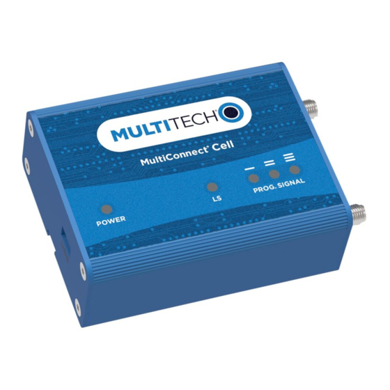
PRODUCT OVERVIEW Descriptions of LEDs The top panel contains the following LEDs: Power and Terminal Ready LEDs—The Power LED indicates that DC power is present and the TR LED indicates when the unit is ready to receive data. Modem LEDs—Two modem LEDs indicate carrier detection and link status. Signal LEDs—Three signal LEDs display the signal strength level of the wireless connection. -
Page 9: Side Panels
PRODUCT OVERVIEW Side Panels The device has connectors on either side. The figures that follow show the side panels. Serial Note: The power-saving switch—which appears with the NORMAL and LOW POWER labels—is included only on models that have a serial connector. ®... -
Page 10: Mtc-Leu4 Specifications
Power Requirements Operating Voltage Serial Models: 5-32 VDC USB Models: 5 VDC * Applies only when using a DC-fused power cable or power supply rated for 60° C. For information regarding extended range, please contact MultiTech. Category Description ® MultiConnect... -
Page 11: Frequency Bands (Leu4)
PRODUCT OVERVIEW Category Description Point-to-Point messaging Mobile-Terminated SMS Mobile-Originated SMS Certifications and Compliance EMC Compliance CE Mark, RED (EU) Radio Compliance CE Mark, RED (EU) Safety Compliance IEC 60950-1 2nd ED Network Compliance Carrier EU Carriers Frequency Bands (LEU4) Mode Freq. -
Page 12: Le910 Telit Transmission Output Power
PRODUCT OVERVIEW LE910 Telit Transmission Output Power Band Power Class GSM 850/900 MHz 4 (2W) DCS 1800, PCS 1900 MHz 1 (1W) EDGE, 850/900 MHz E2 (0.5W) EDGE, 1800/1900 MHz Class E2 (0.4W) WCDMA/FDD 800/850/900, 1900/2100 MHz Class 3 (0.25W) LTE FDD 700/800/850/900, 1800/1900/2100/2600 Class 3 (0.2W) ®... -
Page 13: Rs-232 9-Pin Female Connector
PRODUCT OVERVIEW RS-232 9-Pin Female Connector Abbreviation Description In/Out Carrier Detect Receive Transmit Data Terminal Ready Ground Data Set Ready Request to Send Clear to Send Ring Indicator ® MultiConnect Cell MTC-LEU4 User Guide... -
Page 14: Power Measurements
PRODUCT OVERVIEW Power Measurements Multi-Tech Systems, Inc. recommends incorporating a 10% buffer into your power source when determining product load. Serial Model: MTC-LEU4-B01 Power Draw Radio Sleep mode Cellular call Average Average TX Total inrush Total inrush Protocol current, measured pulse charge, in charge... -
Page 15: Chapter 2 - Safety Warnings
Do not place the device alongside computer discs, credit or travel cards, or other magnetic media. The information contained on discs or cards may be affected by the device. Using accessories, such as antennas, that MultiTech has not authorized or that are not compliant with MultiTech's accessory specifications may invalidate the warranty. -
Page 16: Radio Frequency (Rf) Safety
SAFETY WARNINGS If incorrectly installed in a vehicle, operating the wireless device could interfere with the vehicle’s electronics. To avoid such problems, use qualified personnel to install the device. The installer should verify the vehicle electronics are protected from interference. Using an alert device to operate a vehicle’s lights or horn is not permitted on public roads. -
Page 17: Notice Regarding Compliance With Fcc, Eu, And Industry Canada Requirements For Rf Exposure
SAFETY WARNINGS Keep the device on the opposite side of the body from the pacemaker to add extra distance between the pacemaker and the device. Avoid placing a turned-on device next to the pacemaker (for example, don’t carry the device in a shirt or jacket pocket directly over the pacemaker). -
Page 18: Chapter 3 - Installing And Using The Device
INSTALLING AND USING THE DEVICE Chapter 3 – Installing and Using the Device Installing the Device Connect suitable antenna(s) to the antenna connector(s). If your device is the serial version: Connect the DE9 male connector (9-pin) of the RS-232 cable to the RS-232 connector on the device, then connect the other end to the serial port on the other desired device. -
Page 19: Usb Cable Recommendations
If possible, use a USB port that connects directly to the motherboard rather than a USB port with added cabling inside the computer chassis. Use USB 3.0 ports if available. These ports are typically rated for more current. You can order the USB cable through MultiTech. The part number is CA-USB-A-MINI-B-3 Powering Down Your Device CAUTION: Failing to properly power down the device before removing power may corrupt your device's file system. -
Page 20: Removing A Sim Card
Some environments are harsher on particular bands. MultiTech products have antenna connectors at the best spacing for the product size. Placing antennas in close proximity to each other is not optimal, but you can do it if necessary. It depends on the signal strength to and from each antenna. -
Page 21: Diversity And Power Draw
All antennas need to have a minimum flammability rating. Safety requirements depend on your final product. Unless otherwise noted, antennas certified by MultiTech are not approved for outdoor use. Do not extend these antennas outside of any building. Diversity and Power Draw There are no significant power draw differences. -
Page 22: Chapter 4 - Antenna And Activation Information
LTE Cat M1/Cat 4 Antenna Devices were approved with the following antenna or for alternate antennas meeting the given specifications: Manufacturer: Wieson Description: LTE Antenna with SMA-Male Connector Model Number GY115IE002-001 MultiTech ordering information: Model Quantity ANLTE4-1HRA ANLTE4-2HRA ANLTE4-10HRA ANLTE4-50HRA Antenna Specifications... -
Page 23: Account Activation For Cellular Devices
Account Activation for Cellular Devices Some MultiTech devices are pre-configured to operate on a specific cellular network. To use the device, you must set up a cellular data account with your service provider. Each service provider has its own process for adding devices to their network. -
Page 24: Chapter 5 - Configuring And Communicating With Your Device
CONFIGURING AND COMMUNICATING WITH YOUR DEVICE Chapter 5 – Configuring and Communicating with Your Device Before Using the Device Before using the device: Install any drivers. Refer to the separate driver installation guide for your device. Power up your device and ensure it is connected to your computer that issues AT commands. Note: Wait 10 seconds after power-up before issuing any AT commands. -
Page 25: Example
CONFIGURING AND COMMUNICATING WITH YOUR DEVICE <rssi> Received signal strength indication. (-113) dBm or less (-111) dBm 2-30 (-109) dBm - (-53) dBm / 2 dBm per step (-51) dBm or greater Not known or not detectable <sq> LTE - RSRQ (in dBm): -4 to -3 -6 to -5 -8 to -7... -
Page 26: Sending And Receiving Data
CONFIGURING AND COMMUNICATING WITH YOUR DEVICE The device is registered. If the device returns: AT+CEREG?: 0,2 The device is in a network searching state. Sending and Receiving Data Connecting Device to TCP Server as TCP Client AT+CGDCONT=1,"IPV4V6","apnname" where apnname is the APN your cellular provider assigned to your SIM card. Bring up Data Connection Using Internal IP stack Enter: AT#SGACT=1,1... -
Page 27: Configuring Device As Udp Client To Connect To Udp Server
CONFIGURING AND COMMUNICATING WITH YOUR DEVICE Verify device is registered on the cellular network. Enter: Should return: +CEREG: 0,1 or +CEREG: 0,5 Configure socket parameters Enter: AT#SCFG=1,3,300,240,600,50 Activate context one Enter: AT#SGACT=1,1 Set firewall rule to accept connections: AT#FRWL=1,"###.##.###.#","###.##.###.#" where ###.##.###.# represents the IP range. For example: AT#FRWL=1,"204.26.122.1","204.26.122.255"... -
Page 28: Transferring Ftp File To Ftp Server
CONFIGURING AND COMMUNICATING WITH YOUR DEVICE Enter: AT+CSQ Verify device is registered on the cellular network. Enter: AT+CEREG? Should return: +CEREG: 0,1 or +CEREG: 0,5 Configure socket parameters Enter: AT#SCFG=1,3,300,240,600,50 Activate context one Enter: AT#SGACT=1,1 Create UDP connection to Server port Enter: AT#SD=1,1,####,"###.##.###.##"... -
Page 29: Downloading File From Ftp Server
CONFIGURING AND COMMUNICATING WITH YOUR DEVICE Activate context one Enter: AT#SGACT=1,1 Set FTP operations timeout to 10 seconds Enter: AT#FTPTO=1000 Configure FTP server IP address with username and password. Enter: AT#FTPOPEN="###.##.###.#","username","password",0 where ###.##.###.# is the IP address and the username and password for the FTP server. Configure file transfer type. - Page 30 CONFIGURING AND COMMUNICATING WITH YOUR DEVICE Enter: AT+CEREG? Should return: +CEREG: 0,1 or +CEREG: 0,5 Activate context one Enter: AT#SGACT=1,1 Set FTP operations timeout to 10 seconds Enter: AT#FTPTO=1000 Configure FTP server IP address with username and password. Enter: AT#FTPOPEN="###.##.###.#","username","password",0 where ###.##.###.# is the IP address and the username and password for the FTP server.
-
Page 31: Reading, Writing And Deleting Messages
CONFIGURING AND COMMUNICATING WITH YOUR DEVICE Reading, Writing and Deleting Messages Reading Text Messages To read a text message in text mode: Send a message to the phone number of the currently installed SIM. Put the device in text mode. Enter: AT+CMGF=1 Read message. -
Page 32: Deleting Messages
CONFIGURING AND COMMUNICATING WITH YOUR DEVICE The device responds: +CMGS: # where # is the reference number of the sent message. For example: AT+CMGF=1 AT+CMGS="0001112222" > How are you? <CTRL+Z to send> +CMGS: 255 Where 0001112222 is the phone number. Deleting Messages To delete one text message, enter: AT+CMGD=1,#... -
Page 33: Chapter 6 - Regulatory Information
Council Directive 2014/53/EU on radio equipment and telecommunications terminal equipment and the mutual recognition of their conformity. MultiTech declares that this device is in compliance with the essential requirements and other relevant provisions of Directive 2014/53/EU. The declaration of conformity may be requested at https://support.multitech.com. -
Page 34: Information On Hs/Ts Substances According To Chinese Standards
REGULATORY INFORMATION Information on HS/TS Substances According to Chinese Standards In accordance with China's Administrative Measures on the Control of Pollution Caused by Electronic Information Products (EIP) # 39, also known as China RoHS, the following information is provided regarding the names and concentration levels of Toxic Substances (TS) or Hazardous Substances (HS) which may be contained in Multi-Tech Systems Inc. -
Page 35: Information On Hs/Ts Substances According To Chinese Standards (In Chinese)
REGULATORY INFORMATION Information on HS/TS Substances According to Chinese Standards (in Chinese) 依 依 照 照 中 中 国 国 标 标 准 准 的 的 有 有 毒 毒 有 有 害 害 物 物 质 质 信 信 息 息 根据中华人民共和国信息产业部... -
Page 36: Chapter 7 - Using Connection Manager
Follow these steps in order. Attempting to plug in the device before the appropriate drivers are installed can cause the connection to fail. Go to https://www.multitech.com/support/connection-manager. Click Connection Manager. Open or unzip the Connection Manager file and run the installer (.msi file). -
Page 37: Setting Up A Serial Device
USING CONNECTION MANAGER Setting Up a Serial Device Connect the serial device to the PC. Navigate to Control Panel > Device Manager. Make note of the COM port number for the connected device (in COM Ports). Example: COM port is COM31. In the Action drop-down menu, select Add legacy hardware to add a new device. - Page 38 USING CONNECTION MANAGER Click Browse and select the installation folder. Example: C:\Program Files (x86)\Multi-Tech Systems\Multi-Tech Connection Manager. The list of available TELIT models appears. Select the model number for your device, then click Next. ® MultiConnect Cell MTC-LEU4 User Guide...
-
Page 39: Troubleshooting
USING CONNECTION MANAGER Select the COM port that you noted from COM ports, then click Next. Click Finish to exit the Wizard. Navigate to Device Manager > Modems and confirm that the device is added. Troubleshooting Serial COM port is not available in the Serial Modem Settings This can happen if the modem was installed while Connection Manager was running. -
Page 40: Multiconnect Cell Usb Modem Is Not Detected
USING CONNECTION MANAGER Restart Connection Manager. Disconnect and reconnect the device. MultiConnect Cell USB Modem is not detected Check the Power and LS LEDs on the device. If they are not continuously lit, then the problem is with the power supply. Check the cable and connections. USB device: Make sure that the device is connected to the PC and that the correct USB cable is in use.
Need help?
Do you have a question about the MultiConnect Series 100 and is the answer not in the manual?
Questions and answers