Multitech MTC-LEU4 - MultiConnect Cell 100 Series Cellular Modem Quick Start
- User manual (40 pages) ,
- User manual (45 pages)
Advertisement
Overview
The MultiConnect® Cell 100 Series Cellular Modem (MTC-LEU4) provides secure data communication between many types of devices that use legacy and the latest communication technologies.
Note: Check for an updated version of this document at http://www.multitech.com/brands/multiconnect-cell-100-series
Package Contents
Your MultiConnect® Cell 100 Series Cellular Modem (MTC-LEU4) typically includes the following (varies with model):
| Power Supply | 1 - 9 VDC power supply with removable blades, 1 NAM blade/plug, 1 - EURO blade/plug, 1 - UK blade/plug, 1-AU/NZ blade/plug (serial units) |
| Cables | 1 - Power cable from power supply (serial units) or USB cable (USB units) |
| Antennas | 2 - LTE external antennas, CELL and AUX |
| Documents | 1 - Quick Start Guide, 1 - Warranty Plans, 1 - Activation, Support & Regulatory Information |
| Other Items | 1 - Mounting rod, 4 - Clear adhesive bumpons or mounting feet |
| Device | 1- MultiConnect® Cell 100 Series Cellular Modem (LTE Cat 4) |
Additional Information
For more information on your device, refer to the appropriate user guide:
http://www.multitech.com/brands/multiconnect-cell-100-series
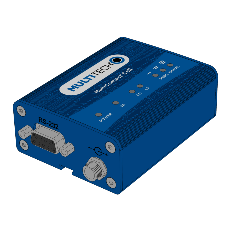
LED Descriptions
The top panel contains the following LEDs:

- Power and Terminal Ready LEDs - The Power LED indicates that DC power is present. The TR LED (serial model only) when lit indicates that unit is ready to receive data.
- Modem LEDs - Two modem LEDs indicate carrier detection (CD LED for serial models only) and link status (LS LED).
- Programmable Signal LEDs - Three signal LEDs can be programmed to display the signal strength level of the wireless connection.
Side Panel Connectors
Serial Models

USB Models

The device has connectors on both sides of the enclosure.
The right side includes:
- AUX Cellular auxiliary female SMA connector (for diversity)
- CELL cellular female SMA connector
- SIM card slot
- Power-saving switch (serial models only)
The left side includes:
- 7-32 VDC power connector
- RS-232 (DE 9-pin, female-D) connector (serial models only)
- USB connector (USB models only)
Dimensions
The MTC is 4.169 inches x 3.00 inches x 1.163 inches
Regulatory Information
For additional regulatory information, see your device's user guide or go to your device's page on www.multitech.com
RED Compliance (EU)
MultiTech declares that this device is in compliance with the essential requirements and other relevant provisions of Directive 2014/53/EU. The declaration of conformity may be requested at https://support.multitech.com.

Changes or modifications to this unit not expressly approved by the party responsible for compliance could void the user's authority to operate the equipment.
Installing a SIM Card

If you want to operate the modem on a particular cellular network, install a mini-SIM card [or mini SIM (2FF) form factor].
To install the mini-SIM card:
- Locate the mini-SIM card slot on the side of the cellular modem. The slot is labeled SIM.
- Push the mini-SIM card into the slot until it snaps into place.
Installing the Cellular Modem
- Connect the suitable antennas to the antenna connectors (CELL and AUX).
- To connect to the serial interface on the cellular modem (serial version only):
- Connect the DE-9 connector (9-pin) of an RS- 232 cable to the RS-232 connector on the cellular modem.
- Connect the other end to the serial port on your computer or other desired device.
- Screw on the power lead from the power supply module into the power connection on the cellular modem.
- Plug the power supply into your power source.
- To connect to the USB interface on the cellular modem (USB version only):
- Connect the mini-USB connector end of the cable to the USB connector on the cellular modem.
- Connect the other end of the USB cable to your computer, either directly or through a hub.
- After power is applied:
- The POWER LED lights after the device powers up.
- When the LS LED begins to blink, the device is registered.
Mounting Device
- Locate the groove on the bottom of the cellular modem.
- Slide the mounting rod through the groove.
- To secure the rod to the desired surface, place and tighten two screws in the holes on either end of the mounting rod. Refer to the user guide for an illustration of the mounting rod, as well as the dimensions for placement of the screws.

Documents / Resources
References
![www.multitech.com]() Industrial Cellular Modem for Sale | MultiTech Cell 100 Cellular Modem
Industrial Cellular Modem for Sale | MultiTech Cell 100 Cellular Modem![www.multitech.com]() MultiTech: IoT Devices & Hardware Company | IoT Device Management
MultiTech: IoT Devices & Hardware Company | IoT Device ManagementMultiTech Product Support Portal
Download manual
Here you can download full pdf version of manual, it may contain additional safety instructions, warranty information, FCC rules, etc.
Download Multitech MTC-LEU4 - MultiConnect Cell 100 Series Cellular Modem Quick Start
Advertisement


Need help?
Do you have a question about the MTC-LEU4 and is the answer not in the manual?
Questions and answers