
Subscribe to Our Youtube Channel
Related Manuals for Texas Instruments EK-TM4C123GXL


Summary of Contents for Texas Instruments EK-TM4C123GXL
- Page 1 ™ Tiva C Series TM4C123G LaunchPad Evaluation Board User's Guide Literature Number: SPMU296 April 2013...
-
Page 2: Table Of Contents
Programming the Tiva C Series LaunchPad Evaluation Board ..............References, PCB Layout, and Bill of Materials ......................... References ..................... Component Locations ....................Bill of Materials (BOM) ........................Schematics Contents SPMU296 – April 2013 Submit Documentation Feedback Copyright © 2013, Texas Instruments Incorporated... - Page 3 J3 Connector ....................... 2-6. J4 Connector ................2-7. In-Circuit Debug Interface (ICDI) Signals ....................2-8. Virtual COM Port Signals ..................4-1. EK-TM4C123GXL Bill of Materials SPMU296 – April 2013 List of Figures Submit Documentation Feedback Copyright © 2013, Texas Instruments Incorporated...
-
Page 4: Board Overview
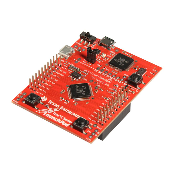
Chapter 1 SPMU296 – April 2013 Board Overview The Tiva™ C Series TM4C123G LaunchPad Evaluation Board (EK-TM4C123GXL) is a low-cost evaluation platform for ARM Cortex™-M4F-based microcontrollers. The Tiva C Series LaunchPad design ® highlights the TM4C123GH6PMI microcontroller USB 2.0 device interface, hibernation module, and motion control pulse-width modulator (MC PWM) module. -
Page 5: Kit Contents
Kit Contents www.ti.com Kit Contents The Tiva C Series TM4C123G LaunchPad Evaluation Kit contains the following items: • Tiva C Series LaunchPad Evaluation Board (EK-TM4C123GXL) • On-board In-Circuit Debug Interface (ICDI) • USB micro-B plug to USB-A plug cable •... -
Page 6: Boosterpacks
(L x W x H) • 3.3 V (300 mA max) Break-out power output • 5.0 V (depends on 3.3 V usage, 23 mA to 323 RoHS status Compliant Board Overview SPMU296 – April 2013 Submit Documentation Feedback Copyright © 2013, Texas Instruments Incorporated... -
Page 7: Hardware Description
SRAM, and 80-MHz operation; USB host, device, and OTG connectivity; a Hibernation module and PWM; and a wide range of other peripherals. See the TM4C123GH6PM microcontroller data sheet (literature number SPMS376) for complete device details. SPMU296 – April 2013 Hardware Description Submit Documentation Feedback Copyright © 2013, Texas Instruments Incorporated... -
Page 8: Usb Connectivity
2.1.2 USB Connectivity The EK-TM4C123GXL is designed and functions as a USB device without hardware modification. The USB device signals are dedicated to USB functionality and are not shared with the BoosterPack headers. -
Page 9: User Switches And Rgb User Led
– 1.10 – – – – I2C1SDA – M1PWM3 – – – – – – Shaded cells indicate configuration for compatibility with the MSP430 LaunchPad. SPMU296 – April 2013 Hardware Description Submit Documentation Feedback Copyright © 2013, Texas Instruments Incorporated... -
Page 10: J2 Connector
– – 3.10 – – U1CTS SSI1Tx – – M1PWM5 – T0CCP1 – TRD1 – Shaded cells indicate configuration for compatibility with the MSP430 LaunchPad. Hardware Description SPMU296 – April 2013 Submit Documentation Feedback Copyright © 2013, Texas Instruments Incorporated... -
Page 11: Power Management
You must satisfy one of the programmed wake conditions and connect the power to bring the microcontroller out of Hibernate mode and turn on the board. SPMU296 – April 2013 Hardware Description Submit Documentation Feedback Copyright © 2013, Texas Instruments Incorporated... -
Page 12: Clocking
COM port to the pins on the microcontroller. Table 2-8. Virtual COM Port Signals GPIO Pin Pin Function U0RX U0TX Hardware Description SPMU296 – April 2013 Submit Documentation Feedback Copyright © 2013, Texas Instruments Incorporated... -
Page 13: Software Development
Sourcery CodeBench • Texas Instruments' Code Composer Studio™ IDE Download evaluation versions of these tools from the TI website. Due to code size restrictions, the evaluation tools may not build all example programs. A full license is necessary to re-build or debug all examples. -
Page 14: Programming The Tiva C Series Launchpad Evaluation Board
4. Verify that the POWER LED D4 on the board is lit. 5. Run the LM Flash Programmer. 6. In the Configuration tab, use the Quick Set control to select the EK-TM4C123GXL evaluation board. 7. Move to the Program tab and click the Browse button. Navigate to the example applications directory (the default location is C:\ti\TivaWare_C_Series_<version>\examples\boards\ek-tm4c123gxl ). -
Page 15: References, Pcb Layout, And Bill Of Materials
TivaWare for C Series Driver Library User’s Manual (literature number SPMU298). • TPS73633 Low-Dropout Regulator with Reverse Current Protection Data Sheet (literature number SBVS038) • Texas Instruments’ Code Composer Studio IDE website: www.ti.com/ccs Additional support: • RealView MDK (www.keil.com/arm/rvmdkkit.asp) •... -
Page 16: Component Locations
Figure 4-1 and the board dimensions are shown in Figure 4-2. Figure 4-1. Tiva C Series LaunchPad Component Locations (Top View) References, PCB Layout, and Bill of Materials SPMU296 – April 2013 Submit Documentation Feedback Copyright © 2013, Texas Instruments Incorporated... -
Page 17: Bill Of Materials (Bom)
NOTE: Units are in mils (one thousandth of an inch): 1 mil = 0.001 inch (0.0254 mm). Bill of Materials (BOM) Table 4-1 shows the bill of materials for the EK-TM4C123GXL evaluation board. Table 4-1. EK-TM4C123GXL Bill of Materials Item... - Page 18 Bill of Materials (BOM) www.ti.com Table 4-1. EK-TM4C123GXL Bill of Materials (continued) Item Ref Des Description Manufacturer Manufacturer Part No USB Connector, Micro B Recept Hirose ZX62-B-5PA RA SMT BTTM MNT J2, J4 Header, 1x2, 0.100, SMT, Samtec TSM-110-01-S-DH-A-P-TR Horizontal Unshrouded, 0.230...
-
Page 19: A Schematics
This section contains the complete schematics for the Tiva C Series LaunchPad board. • Microcontroller, USB, Expansion, Buttons, and LED • Power Management • In-Circuit Debug Interface SPMU296 – April 2013 Schematics Submit Documentation Feedback Copyright © 2013, Texas Instruments Incorporated... - Page 20 DTC114EET1G TEXAS INSTRUMENTS DESIGNER REVISION DATE 2/20/2013 PROJECT TIVA MICROCONTROLLERS Tiva TM4C123G LaunchPad 108 WILD BASIN ROAD, SUITE 350 LED_B DTC114EET1G AUSTIN TX, 78746 DESCRIPTION www.ti.com Microcontroller, USB, Expansion, Buttons and LED FILENAME PART NO. SHEET EK-TM4C123GXL Rev A.sch EK-TM4C123GXL...
- Page 21 OMIT this SVS Section for Tiva. Errata Fixed DESIGNER REVISION DATE TEXAS INSTRUMENTS 2/20/2013 PROJECT TIVA MICROCONTROLLERS Tiva Launchpad 108 WILD BASIN ROAD, SUITE 350 AUSTIN TX, 78746 DESCRIPTION www.ti.com Power Management FILENAME PART NO. SHEET EK-TM4C123GXL Rev A.sch EK-TM4C123GXL...
- Page 22 TM4C123G 0.1uF 0.1uF 2.2uF 1.0uF DESIGNER REVISION DATE TEXAS INSTRUMENTS 2/20/2013 PROJECT TIVA MICROCONTROLLERS Tiva TM4C123G LaunchPad 108 WILD BASIN ROAD, SUITE 350 DESCRIPTION AUSTIN TX, 78746 In Circuit Debug Interface www.ti.com FILENAME PART NO. SHEET EK-TM4C123GXL Rev A.sch EK-TM4C123GXL...
- Page 23 Any exceptions to this are strictly prohibited and unauthorized by Texas Instruments unless user has obtained appropriate experimental/development licenses from local regulatory authorities, which is responsibility of user including its acceptable authorization.
- Page 24 FCC Interference Statement for Class B EVM devices This equipment has been tested and found to comply with the limits for a Class B digital device, pursuant to part 15 of the FCC Rules. These limits are designed to provide reasonable protection against harmful interference in a residential installation. This equipment generates, uses and can radiate radio frequency energy and, if not installed and used in accordance with the instructions, may cause harmful interference to radio communications.
- Page 25 Also, please do not transfer this product, unless you give the same notice above to the transferee. Please note that if you could not follow the instructions above, you will be subject to penalties of Radio Law of Japan. Texas Instruments Japan Limited (address) 24-1, Nishi-Shinjuku 6 chome, Shinjuku-ku, Tokyo, Japan http://www.tij.co.jp...
- Page 26 FDA Class III or similar classification, then you must specifically notify TI of such intent and enter into a separate Assurance and Indemnity Agreement. Mailing Address: Texas Instruments, Post Office Box 655303, Dallas, Texas 75265 Copyright © 2013, Texas Instruments Incorporated...
- Page 27 IMPORTANT NOTICE Texas Instruments Incorporated and its subsidiaries (TI) reserve the right to make corrections, enhancements, improvements and other changes to its semiconductor products and services per JESD46, latest issue, and to discontinue any product or service per JESD48, latest issue.
Need help?
Do you have a question about the EK-TM4C123GXL and is the answer not in the manual?
Questions and answers