
Related Manuals for Texas Instruments EVMK2G


Summary of Contents for Texas Instruments EVMK2G
- Page 1 Evaluation Modules for the the 66AK2Gxx DSP + ARM processors (EVMK2G, EVMK2GX, and EVMK2GXS) User's Guide Literature Number: SPRUI65A April 2016 – Revised January 2018...
-
Page 2: Table Of Contents
UART ................... 3.25 Audio Expansion Connector ................... 3.26 Serial Expansion Connector ....................3.27 I2C Address Mapping ....................3.28 McASP Configuration Table of Contents SPRUI65A – April 2016 – Revised January 2018 Submit Documentation Feedback Copyright © 2016–2018, Texas Instruments Incorporated... - Page 3 Removing and Installing a K2G in the Socket ..................10.2 Initial Use of a Socketed Board ......................EVM Important Notice .......................... Revision History SPRUI65A – April 2016 – Revised January 2018 Contents Submit Documentation Feedback Copyright © 2016–2018, Texas Instruments Incorporated...
- Page 4 List of Figures ................ EVMK2G Board Assembly Pictorial - Top View ..............EVMK2G Board Assembly Pictorial - Bottom View ..................EVMK2G Functional Block Diagram ................... Over Voltage Protection Circuit ..................... Fault Indication Circuit ................Display and Trace Resistor Multiplexing ...................
- Page 5 ......................Ironwood Socket SPRUI65A – April 2016 – Revised January 2018 List of Figures Submit Documentation Feedback Copyright © 2016–2018, Texas Instruments Incorporated...
- Page 6 DB9 Connector (P1, P2, and P3) Pin List ....................EVMK2G Tactile Switches ..................Boot Mode Configurations for SW3 ..................... EVMK2G Board LEDs List of Tables SPRUI65A – April 2016 – Revised January 2018 Submit Documentation Feedback Copyright © 2016–2018, Texas Instruments Incorporated...
-
Page 7: Preface
Evaluation Module (EVMK2G) designed and developed by Mistral Solutions Pvt. Ltd. The 66AK2Gxx is a KeyStone™ II-based DSP + ARM System-on-Chip (SoC). There are three variants of the EVM for the K2G. These include the EVMK2G, the EVMK2GX, and the EVMK2GXS. - Page 8 Board History www.ti.com Trademarks KeyStone, E2E, Code Composer Studio, Tiva, WiLink are trademarks of Texas Instruments. ARM, Cortex are registered trademarks of ARM Limited. Read This First SPRUI65A – April 2016 – Revised January 2018 Submit Documentation Feedback Copyright © 2016–2018, Texas Instruments Incorporated...
-
Page 9: Introduction
This user's guide describes the hardware architecture of the 66AK2Gxx General Purpose (GP) Evaluation Module (EVMK2G) designed and developed by Mistral Solutions Pvt. Ltd. The 66AK2Gxx is a KeyStone™ II-based DSP + ARM System-on-Chip (SoC). There are three variants of the K2G EVM. -
Page 10: Description
• 21 × 2 mm 0.8mm pitch WBBGA System View The top and the bottom pictorial views of the EVMK2G are provided in Figure 1 Figure 2, respectively. What's in the Box? The EVMK2G Kit contains the following parts: •... -
Page 11: Evmk2G Board Assembly Pictorial - Top View
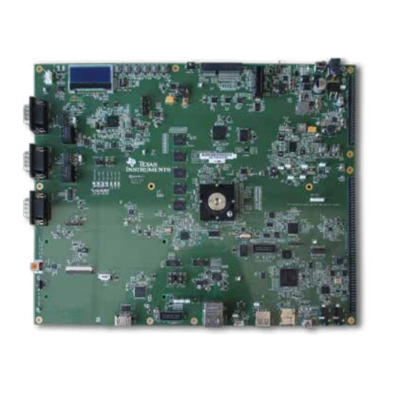
Introduction www.ti.com Figure 1. EVMK2G Board Assembly Pictorial - Top View 66AK2Gxx PCIe Controller Connector COM8 +12 V DC JTAG Connector UART0 Serial DCAN0 Expansion Connector DCAN1 UART0 Audio Over DB9 Expansion Connector UART2 MiPi 60 SoC UART0 Connector &... -
Page 12: Evmk2G Board Assembly Pictorial - Bottom View
Introduction www.ti.com Figure 2. EVMK2G Board Assembly Pictorial - Bottom View NAND Flash K2G General Purpose Evaluation Module (EVMK2G) SPRUI65A – April 2016 – Revised January 2018 Submit Documentation Feedback Copyright © 2016–2018, Texas Instruments Incorporated... -
Page 13: Acronyms
Serial Peripheral Interfaces UART Universal Asynchronous Receiver/Transmitter Universal Serial Bus XDS200 Texas Instruments’ Emulator Testing and Results Overview Setup SPRUI65A – April 2016 – Revised January 2018 K2G General Purpose Evaluation Module (EVMK2G) Submit Documentation Feedback Copyright © 2016–2018, Texas Instruments Incorporated... -
Page 14: Test Points
Testing and Results www.ti.com Test Points The EVMK2G board has 187 test points. Each test point and its function is given in Table Table 2. EVMK2G Test Points Test Test Test Test Point Signal Point Signal Point Signal Point Signal... -
Page 15: System Description
(IDE). It is recommended to use CCS revision 6.1.2 or later with the EVMK2G. The Processor SDK Linux images are preprogrammed to the SD Card that is shipped with the EVMK2G. Refer to the Processor SDK user guide for more details on running Linux with the EVM. -
Page 16: Evmk2G Functional Block Diagram
System Description www.ti.com Figure 3. EVMK2G Functional Block Diagram To DSS-UL connectors, due to pin muxing. Need isolation in between. Serial expansion header MIPI Connector Micrel NSS (RGMII) RJ45 KSZ9031RNX Mini- JTAG 25 MHz XDS200 PHY can also be clocked... -
Page 17: Over Voltage Protection Circuit
Over Voltage Protection Circuit The Voltage Protection Circuit on the EVMK2G protects the board from over voltage, under voltage, transient voltage, and reverse voltage input cases. The safe operation input voltage range is 11v to 13v. Any voltage not in this range is considered a fault and the voltage protection circuit... -
Page 18: Jtag Emulation Overview
3.4.1 On-Board XDS200 Emulator The EVMK2G has on-board XDS200 embedded JTAG emulation circuitry. Hence user does not require any external emulator to connect EVM with Code Composer Studio (CCS). You can connect the target SoC in the EVM to CCS through the USB cable supplied in the EVM kit. -
Page 19: Jtag Interface Block Diagram
DQ0-15 CONTROL A0-11 SIGNALS SPI1 6 BA0-1 SPI FLASH SD RAM Copyright © 2016, Texas Instruments Incorporated SPRUI65A – April 2016 – Revised January 2018 K2G General Purpose Evaluation Module (EVMK2G) Submit Documentation Feedback Copyright © 2016–2018, Texas Instruments Incorporated... -
Page 20: Board Management Controller (Bmc)
® ® management controller for the EVMK2G. The BMC controls the SoC boot sequence and displays the status on the character LCD interfaced to the BMC. The BMC facilitates the selection of Boot mode, reset settings, and configuring clock generators. -
Page 21: Board Management Controller (Bmc) Block Diagram
Isolator JTAG Lines JTAG 14 Pin Connector GPIOs BMC_RESETn Push Button Copyright © 2016, Texas Instruments Incorporated SPRUI65A – April 2016 – Revised January 2018 K2G General Purpose Evaluation Module (EVMK2G) Submit Documentation Feedback Copyright © 2016–2018, Texas Instruments Incorporated... -
Page 22: Clock Distribution
System Description www.ti.com Clock Distribution The EVMK2G has the following clock sources, crystals, and oscillators. • 66AK2Gxx SoC clocks (see Figure – Y5: 22.579 MHz Audio clock for SoC – Y6: 24 MHz System clock to the SoC – Y7: 12.28 MHz to CS2000 –... -
Page 23: Other Clocks Block Diagram
Figure 10. Other Clocks Block Diagram PMIC KSZ9031RNX 32.768 kHz Audio Codec 12.288MHz HDMI TX AM1802 Copyright © 2016, Texas Instruments Incorporated SPRUI65A – April 2016 – Revised January 2018 K2G General Purpose Evaluation Module (EVMK2G) Submit Documentation Feedback Copyright © 2016–2018, Texas Instruments Incorporated... -
Page 24: Ddr3L Interface
DDR3L MT41K512M8RH MT41K512M8RH MT41K512M8RH MT41K512M8RH MT41K512M8RH -125:E -125:E -125:E -125:E -125:E Copyright © 2016, Texas Instruments Incorporated K2G General Purpose Evaluation Module (EVMK2G) SPRUI65A – April 2016 – Revised January 2018 Submit Documentation Feedback Copyright © 2016–2018, Texas Instruments Incorporated... -
Page 25: Nand Flash
GPMC_OEn_REN NAND FLASH K2G SoC GPMC_WEn MT29F2G16ABA GPMC_WPn GPMC_CSn0 GPMC_WAIT0 R/B# Copyright © 2016, Texas Instruments Incorporated SPRUI65A – April 2016 – Revised January 2018 K2G General Purpose Evaluation Module (EVMK2G) Submit Documentation Feedback Copyright © 2016–2018, Texas Instruments Incorporated... -
Page 26: Spi Flash
K2G SoC SPI1_CSn0 N25Q128A13ESF40F GPIO #HOLD RESET# FLASH_WP# FLASH_RESET# AND GATE SOC_RESETSTATz Copyright © 2016, Texas Instruments Incorporated K2G General Purpose Evaluation Module (EVMK2G) SPRUI65A – April 2016 – Revised January 2018 Submit Documentation Feedback Copyright © 2016–2018, Texas Instruments Incorporated... -
Page 27: Quad Spi (Qspi) Flash
Figure 15. EEPROM Interface Block Diagram 3.3 V I2C2_SCL K2G SoC I2C2_SDA EEPROM AT24CM01 EEPROM_WP Copyright © 2016, Texas Instruments Incorporated SPRUI65A – April 2016 – Revised January 2018 K2G General Purpose Evaluation Module (EVMK2G) Submit Documentation Feedback Copyright © 2016–2018, Texas Instruments Incorporated... -
Page 28: Sd Card
D [0-8] K2G SoC (eMMC16G-S100) MMC1_D [0-4] MMC1_CMD COM8 Connector MMC1_CLK Copyright © 2016, Texas Instruments Incorporated K2G General Purpose Evaluation Module (EVMK2G) SPRUI65A – April 2016 – Revised January 2018 Submit Documentation Feedback Copyright © 2016–2018, Texas Instruments Incorporated... -
Page 29: Emmc And Com8 Resistor Multiplexing
Connect MMC1 to COM8 RA15, R713, R714, and R393 RA6, R387, R388, and R822 Connect MMC1 to eMMC (default) SPRUI65A – April 2016 – Revised January 2018 K2G General Purpose Evaluation Module (EVMK2G) Submit Documentation Feedback Copyright © 2016–2018, Texas Instruments Incorporated... -
Page 30: Gigabit Ethernet
RGMII_RXD [0-3] RD [0-3] / MODE [0:3] TXRXPD MDIO_CLK TXRXMD MDIO_DATA MDIO Copyright © 2016, Texas Instruments Incorporated K2G General Purpose Evaluation Module (EVMK2G) SPRUI65A – April 2016 – Revised January 2018 Submit Documentation Feedback Copyright © 2016–2018, Texas Instruments Incorporated... -
Page 31: Pcie
The TFT LCD module (NHD-4.3-480272EF-ATXL-CTP) from Newhaven display can be plugged into the 40-pin FPC connector on the EVMK2G. The LCD backlight is driven by DC-DC boost-converter TPS61081DRCT. The LCD is not part of the EVMK2G kit, it should be purchased separately. More details of LCD installation procedure is provided in Section 3.16.2... -
Page 32: Display Interface Block Diagram
SW13 and SW14 Position Signal Result SEL_HDMIn signal is low HDMI is enabled SEL_LCDn signal becomes low LCD is enabled K2G General Purpose Evaluation Module (EVMK2G) SPRUI65A – April 2016 – Revised January 2018 Submit Documentation Feedback Copyright © 2016–2018, Texas Instruments Incorporated... -
Page 33: Touch Connector
DC_BRD_DET High McASP0 is connected to HDMI Transmitter SiI9022A. 3.17 Touch Connector NOTE: The EVMK2G does not come with an LCD Touchscreen display, it should be purchased separately. The Touch Connector interface is shown in Figure Figure 22. Touch Interface Block Diagram... -
Page 34: Com8 Connector
Figure 25. DCAN Interface Block Diagram DCAN_TX DCAN_RX Transceiver Connector K2G SoC ISO1050DUB Copyright © 2016, Texas Instruments Incorporated K2G General Purpose Evaluation Module (EVMK2G) SPRUI65A – April 2016 – Revised January 2018 Submit Documentation Feedback Copyright © 2016–2018, Texas Instruments Incorporated... -
Page 35: Mlb
MLB_PSIGP MLB_PSIGN MLB_PDATP MLB_PDATN MLB_PCLKP K2G SoC MLB_PCLKN MLB_CLK MLB_DAT MLB_SIG Copyright © 2016, Texas Instruments Incorporated SPRUI65A – April 2016 – Revised January 2018 K2G General Purpose Evaluation Module (EVMK2G) Submit Documentation Feedback Copyright © 2016–2018, Texas Instruments Incorporated... -
Page 36: Usb Host
System Description www.ti.com 3.22 USB Host USB0 shall be used for the USB Host interface in the EVMK2G. The USB0ID pin is grounded through a 0- ohm resistor in order to configure it as USB Host as shown in Figure 26. -
Page 37: Uart
System Description www.ti.com 3.24 UART There are three UART ports available in the EVMK2G. UART0 debug port is multiplexed between the DB9 port, USB-to-UART converter (CP2105), and the Serial Expansion header as shown in Figure Table 10. UART0 Multiplexing Signal... -
Page 38: Uart1 Interface Block Diagram
UART1 Buffer BMC_UART_SEL K2G SoC UART2_TX 6 Pin Buffer Header UART2_RX Copyright © 2016, Texas Instruments Incorporated K2G General Purpose Evaluation Module (EVMK2G) SPRUI65A – April 2016 – Revised January 2018 Submit Documentation Feedback Copyright © 2016–2018, Texas Instruments Incorporated... -
Page 39: Audio Expansion Connector
System Description www.ti.com 3.25 Audio Expansion Connector The EVMK2G consists of an audio expansion connector for an audio daughter card. Audio expansion connector contains McASP0, McASP1, and McASP2 signals along with the I2C1, SPI2, and GPIO signals as shown in Figure Figure 32. -
Page 40: Serial Expansion Connector
System Description www.ti.com 3.26 Serial Expansion Connector The EVMK2G consists of a Serial Expansion connector that contains I2C0, SPI0, UART0, Timer 0, Timer1, eHRPWM3, eHRPWM4, eHRPWM5, and eCAP signals as shown in Figure Figure 33. Serial Expansion Connector Interface Block Diagram... -
Page 41: I2C Address Mapping
System Description www.ti.com 3.27 I2C Address Mapping The address mapping for the I2C interface on the EVMK2G is shown in Table 12 Table Table 12. SoC Address Table I2C Used Device Address EEPROM 0x50, 0x51 0x0 (Programmable) I2C0 Serial Expansion Connector... -
Page 42: Mcasp Configuration
MCASP0_AFSR DOUT[0:3] MCASP0_AXR[12:15] MCLKIN BUFFER BCLKIN JUMPER LRCKIN DIN[0:7] BUFFER JUMPER Copyright © 2016, Texas Instruments Incorporated K2G General Purpose Evaluation Module (EVMK2G) SPRUI65A – April 2016 – Revised January 2018 Submit Documentation Feedback Copyright © 2016–2018, Texas Instruments Incorporated... -
Page 43: Power Supply
(by example) UL, CSA, VDE, CCC, PSE, and so on. The EVMK2G can be powered from a single +12V/5.0A DC (60W) external power supply connected to the DC power jack (J3). Internally, +12V input is converted into required voltage levels using local DC-DC converters. -
Page 44: Power Distribution Diagram
EMMC16G-S100 SiI9022ACNU NOTE: REGULATORS DEVICES LDO3_1V8,+1.8V,90mA CLOCK CDCM6208V2RGZT Multiple powered device Copyright © 2016, Texas Instruments Incorporated K2G General Purpose Evaluation Module (EVMK2G) SPRUI65A – April 2016 – Revised January 2018 Submit Documentation Feedback Copyright © 2016–2018, Texas Instruments Incorporated... -
Page 45: Power Supply Calculation
31.00775194 31.00775194 GPIO Expander TCA9555 38.75968992 38.75968992 Temperature Sensor TMP102 0.001453488 0.001453488 LEDs ×7 — 16.95736434 16.95736434 SPRUI65A – April 2016 – Revised January 2018 K2G General Purpose Evaluation Module (EVMK2G) Submit Documentation Feedback Copyright © 2016–2018, Texas Instruments Incorporated... -
Page 46: Power-Up Sequence
PMIC is enabled by the BMC. The BMC is powered on as soon as the board is powered on. The firmware flashed in the BMC enables power to the PMIC. Figure 36. Power-Up Sequence Diagram K2G General Purpose Evaluation Module (EVMK2G) SPRUI65A – April 2016 – Revised January 2018 Submit Documentation Feedback... -
Page 47: Booting
To boot Linux images and run matrix demonstrations on the board, follow these instructions: 1. Set DIP switch (SW3) to 0111 (MSB first), as shown, to select MMC/SD boot mode. SPRUI65A – April 2016 – Revised January 2018 K2G General Purpose Evaluation Module (EVMK2G) Submit Documentation Feedback Copyright © 2016–2018, Texas Instruments Incorporated... - Page 48 Booting www.ti.com 2. Insert the SD card. K2G General Purpose Evaluation Module (EVMK2G) SPRUI65A – April 2016 – Revised January 2018 Submit Documentation Feedback Copyright © 2016–2018, Texas Instruments Incorporated...
- Page 49 3. Using the Ethernet cable, connect the EVM to a network containing a PC running a DHCP server. SPRUI65A – April 2016 – Revised January 2018 K2G General Purpose Evaluation Module (EVMK2G) Submit Documentation Feedback Copyright © 2016–2018, Texas Instruments Incorporated...
- Page 50 4. Connect 12V power cable to the DC power jack (J3). Slide the power switch SW1 to the ON position marked on the silkscreen. LED LD9 lights. K2G General Purpose Evaluation Module (EVMK2G) SPRUI65A – April 2016 – Revised January 2018 Submit Documentation Feedback Copyright ©...
- Page 51 5. Note the IP address displayed on the LCD screen. Enter this address into a web browser connected to the same network as the EVM. SPRUI65A – April 2016 – Revised January 2018 K2G General Purpose Evaluation Module (EVMK2G) Submit Documentation Feedback Copyright © 2016–2018, Texas Instruments Incorporated...
- Page 52 Booting www.ti.com 6. The host PC connects to the EVM, and the demonstration may now be run. K2G General Purpose Evaluation Module (EVMK2G) SPRUI65A – April 2016 – Revised January 2018 Submit Documentation Feedback Copyright © 2016–2018, Texas Instruments Incorporated...
-
Page 53: Connector Descriptions
The EVMK2G is powered by inserting the 12V-DC adapter into this power jack. Mini USB for On-board XDS (J1) and CP2105 (J23) The EVMK2G has 2 mini USB connectors. J1 is for on-board XDS200 circuit. J23 is for SoC UART0 and BMC console over USB. -
Page 54: Evmk2G Board Connectors
Connector Descriptions www.ti.com Figure 37. EVMK2G Board Connectors K2G General Purpose Evaluation Module (EVMK2G) SPRUI65A – April 2016 – Revised January 2018 Submit Documentation Feedback Copyright © 2016–2018, Texas Instruments Incorporated... -
Page 55: Com8 (J2)
Connector Descriptions www.ti.com COM8 (J2) The EVMK2G has a COM8 connector for interfacing to TI WiLink 8 modules. The pin out is given in Table Table 19. COM8 (J2) Pin List Description Description Description Description COM_SLOW_CLK COM_SDIO_D0 COM_BTUARTDEBUG DGND COM_AUD_CLK... -
Page 56: Pci Express (J5)
Connector Descriptions www.ti.com PCI Express (J5) The EVMK2G has x1 PCI express interface to connect PCIe add-on cards. The pin out is given in Table Table 20. PCI Express (J5) Pin List Description Description PRSNT# VCC12V0 VCC12V0 VCC12V0 VCC12V0 VCC12V0... -
Page 57: Jtag Mipi-60 (J19)
Connector Descriptions www.ti.com JTAG MIPI-60 (J19) The EVMK2G has an MIPI connector for JTAG communication to the SoC through an external emulator. The pin out is given in Table Table 21. JTAG MIPI-60 (J19) Pin List Description Description Description EMU01... -
Page 58: Lcd (J22) And Touch Screen (J21)
Connector Descriptions www.ti.com LCD (J22) and Touch Screen (J21) The EVMK2G has a 40-pin FPC LCD and a 6-pin touch screen connector. A 4.3-inch LCD can be connected to the EVM through the connectors shown in Figure 38. The pin out is given in Table Figure 38. - Page 59 2. Safely insert the LCD and Touch Flex cables. Make sure the cables are correctly fitting in the connector. 3. Close the tab. 4. Install the brackets. SPRUI65A – April 2016 – Revised January 2018 K2G General Purpose Evaluation Module (EVMK2G) Submit Documentation Feedback Copyright © 2016–2018, Texas Instruments Incorporated...
-
Page 60: Rj45 Ethernet (J31)
Connector Descriptions www.ti.com RJ45 Ethernet (J31) The EVMK2G has one RJ45 connector with magnetics for Ethernet interface. It is connected to the Ethernet PHY Transceiver through parallel termination. The pin out is given in Table Table 23. RJ45 Ethernet (J31) Pin List... -
Page 61: Mlb (J34)
PCLKP VCC3V3 VCC12V0 6.10 USB0 Host Type A (J35) The EVMK2G has a USB Type A connector as host. The pin out is given in Table 26 Table 26. USB0 Host Type A (J35) Pin List Description ID Pin to GND... -
Page 62: Hdmi (J36)
Connector Descriptions www.ti.com 6.11 HDMI (J36) The EVMK2G has an HDMI out where it can be used to connect to the HDMI monitor via cable. It is a 23- pin Type A Receptacle connector. The pin out is given in Table Table 27. -
Page 63: Mmc/Sd (J37)
CLOCK DAT0 DAT1 SDCD_GND SDCD_GND SDCD_GND SDCD_GND 6.13 USB1-Micro (J38) The EVMK2G has a micro-USB connector as USB1 dual role. The pin out is given in Table Table 29. USB1-Micro (J38) Pin List Description USB0_GND USB0_GND USB0_GND USB0_GND SPRUI65A – April 2016 – Revised January 2018... -
Page 64: Db9 Connector (P1, P2, And P3)
6.14 DB9 Connector (P1, P2, and P3) The EVMK2G has three DB-9 connectors. DB9 connector (P1) is connected to the SoC UART0 through the RS-232 Transceiver. Two DB9 connectors (P2 and P3) are used for DCAN0 and DCAN1, respectively, connected to the SoC through the CAN transceiver. -
Page 65: Switch Descriptions
SW15 SW12 SW14 & SW13 Slide Switch The EVMK2G has one sliding switch/Power switch (SW1) for powering ON/OFF the board. SPRUI65A – April 2016 – Revised January 2018 K2G General Purpose Evaluation Module (EVMK2G) Submit Documentation Feedback Copyright © 2016–2018, Texas Instruments Incorporated... -
Page 66: Tactile Switch
Switch Descriptions www.ti.com Tactile Switch The EVMK2G has 8 tactile switches. Pressing each performs different functions. Switches and their corresponding functions are listed in Table Table 31. EVMK2G Tactile Switches Switch Function Description VOL+ Currently not implemented VOL- Currently not implemented... -
Page 67: Dip Switch
UART0 over USB/DB9 Switch: This switch (SW12) is used to enable UART0 over USB. In the ON condition, UART0 is over DB9 connector. In the OFF condition, UART0 is over USB. SPRUI65A – April 2016 – Revised January 2018 K2G General Purpose Evaluation Module (EVMK2G) Submit Documentation Feedback Copyright © 2016–2018, Texas Instruments Incorporated... -
Page 68: Evm Board Physical Specifications
EVM Board Physical Specifications www.ti.com EVM Board Physical Specifications This section describes the physical layout of the EVMK2G board and its connectors, switches, and test points. NOTE: The EVMK2G does not come with an LCD Touchscreen display, it should be purchased separately. -
Page 69: Evmk2G Mechanical Drawing
EVM Board Physical Specifications www.ti.com Figure 41. EVMK2G Mechanical Drawing SPRUI65A – April 2016 – Revised January 2018 K2G General Purpose Evaluation Module (EVMK2G) Submit Documentation Feedback Copyright © 2016–2018, Texas Instruments Incorporated... -
Page 70: Board Layout
EVM Board Physical Specifications www.ti.com Board Layout The EVMK2G board dimension is 12’ × 9.60’’ (305mm × 244mm). It is a 10-layer board and powered through connector J3. The top and the bottom layout views of the EVMK2G are provided in Figure 42 Figure 43, respectively. -
Page 71: Evmk2G Board Assembly Layout - Bottom View
EVM Board Physical Specifications www.ti.com Figure 43. EVMK2G Board Assembly Layout - Bottom View SPRUI65A – April 2016 – Revised January 2018 K2G General Purpose Evaluation Module (EVMK2G) Submit Documentation Feedback Copyright © 2016–2018, Texas Instruments Incorporated... -
Page 72: System Leds
EVM Board Physical Specifications www.ti.com System LEDs The EVMK2G has 13 LEDs. The description of each LED is given in Table 33 and shown in Figure Table 33. EVMK2G Board LEDs Color Description Yellow SoC_LED1 Yellow SoC_LED3 Yellow SoC_LED0 Yellow... -
Page 73: Evmk2G Board Leds
EVM Board Physical Specifications www.ti.com Figure 44. EVMK2G Board LEDs LD15 LD14 LD11 LD12 LD13 LD10 SPRUI65A – April 2016 – Revised January 2018 K2G General Purpose Evaluation Module (EVMK2G) Submit Documentation Feedback Copyright © 2016–2018, Texas Instruments Incorporated... -
Page 74: Evm With Audio Daughter Card
DAC_OUT 5 DAC1 Mute Switch DAC_OUT 6 DAC_OUT 7 ADC_IN 0 ADC_IN 2 ADC_IN 1 ADC_IN 3 K2G General Purpose Evaluation Module (EVMK2G) SPRUI65A – April 2016 – Revised January 2018 Submit Documentation Feedback Copyright © 2016–2018, Texas Instruments Incorporated... -
Page 75: K2G Audio Daughter Card Block Diagram
Coaxial RCA Connector Coaxial RCA Connector (SN74LVC2G14) McASP0 AXR[0:15] I2S Header GPIO[0,1] Copyright © 2016, Texas Instruments Incorporated SPRUI65A – April 2016 – Revised January 2018 K2G General Purpose Evaluation Module (EVMK2G) Submit Documentation Feedback Copyright © 2016–2018, Texas Instruments Incorporated... -
Page 76: Evm With Audio Daughter Card Connections
Align the pins of the Audio Daughter Card (connectors J63 and J64) with the main card (connectors J12 and JP1), respectively. Press gently to mate the connectors at the corners. K2G General Purpose Evaluation Module (EVMK2G) SPRUI65A – April 2016 – Revised January 2018 Submit Documentation Feedback Copyright ©... - Page 77 Apply pressure on the middle and the sides evenly to ensure proper mating of the connectors. 2. The board looks, as shown, after mating the K2G GP EVM and Audio Daughter Card. SPRUI65A – April 2016 – Revised January 2018 K2G General Purpose Evaluation Module (EVMK2G) Submit Documentation Feedback Copyright © 2016–2018, Texas Instruments Incorporated...
- Page 78 Once the GP EVM has booted, it is safe to turn ON any powered speakers. Powered Speakers Input (12 V / 5 A) Switch SW1 Analog Output Analog input from media K2G General Purpose Evaluation Module (EVMK2G) SPRUI65A – April 2016 – Revised January 2018 Submit Documentation Feedback Copyright © 2016–2018, Texas Instruments Incorporated...
-
Page 79: Evmk2Gxs Secure Evm
EVMK2GXS Secure EVM www.ti.com EVMK2GXS Secure EVM A socketed version of the EVMK2G is available for the development of software to support a secure version of the K2G. Figure 48. Ironwood Socket 10.1 Removing and Installing a K2G in the Socket... -
Page 80: Initial Use Of A Socketed Board
If this occurs, follow the steps above to remove and reinstall the component. EVM Important Notice Refer to the STANDARD TERMS AND CONDITIONS FOR EVALUATION MODULES. K2G General Purpose Evaluation Module (EVMK2G) SPRUI65A – April 2016 – Revised January 2018 Submit Documentation Feedback Copyright © 2016–2018, Texas Instruments Incorporated... -
Page 81: Revision History
Changes from Original (April 2016) to A Revision ......................Page ..........................• Updated Title....................• Updated About This Manual section..................... • Added EVMK2GXS Secure EVM section. SPRUI65A – April 2016 – Revised January 2018 Revision History Submit Documentation Feedback Copyright © 2016–2018, Texas Instruments Incorporated... - Page 82 IMPORTANT NOTICE FOR TI DESIGN INFORMATION AND RESOURCES Texas Instruments Incorporated (‘TI”) technical, application or other design advice, services or information, including, but not limited to, reference designs and materials relating to evaluation modules, (collectively, “TI Resources”) are intended to assist designers who are developing applications that incorporate TI products;...
- Page 83 Mouser Electronics Authorized Distributor Click to View Pricing, Inventory, Delivery & Lifecycle Information: Texas Instruments EVMK2GX...
Need help?
Do you have a question about the EVMK2G and is the answer not in the manual?
Questions and answers