Sign In
Upload
Download
Table of Contents
Contents
Add to my manuals
Delete from my manuals
Share
URL of this page:
HTML Link:
Bookmark this page
Add
Manual will be automatically added to "My Manuals"
Print this page
×
Bookmark added
×
Added to my manuals
Manuals
Brands
Texas Instruments Manuals
Motherboard
Tiva C Series
User manual
Texas Instruments Tiva С Series User Manual
Connected launchpad evaluation kit
Hide thumbs
Also See for Tiva С Series
:
Development manual
(17 pages)
,
User manual
(28 pages)
1
Table Of Contents
2
3
4
5
6
7
8
9
10
11
12
13
14
15
16
17
18
19
20
21
22
23
24
25
26
27
28
29
30
31
32
33
34
35
36
37
38
39
40
41
42
page
of
42
Go
/
42
Contents
Table of Contents
Bookmarks
Table of Contents
Table of Contents
Board Overview
Tiva C Series Connected Launchpad Evaluation Board
Kit Contents
Using the Connected Launchpad
Features
Boosterpacks
Energīa
Specifications
Hardware Description
Functional Description
Microcontroller
Ethernet Connectivity
USB Connectivity
Motion Control
User Switches and Led's
Boosterpacks and Headers
X11 Breadboard Adapter Odd-Numbered Pad GPIO and Signal Muxing
X11 Breadboard Adapter Even-Numbered Pad GPIO and Signal Muxing
Power Management
Power Supplies
Default Jumper Locations
Low Power Modes
Clocking
Reset
Debug Interface
In-Circuit Debug Interface (ICDI)
External Debugger
Virtual COM Port
Software Development
Software Description
Source Code
Tool Options
Programming the Connected Launchpad
References, PCB Layout, and Bill of Materials
References
Component Locations
Connected Launchpad Dimensions and Component Locations
Bill of Materials
Connected Launchpad Bill of Materials
Schematic
Revision History
Advertisement
Quick Links
Download this manual
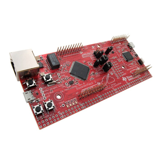
Tiva™ C Series TM4C1294 Connected
LaunchPad Evaluation Kit
EK-TM4C1294XL
User's Guide
Literature Number: SPMU365C
March 2014 – Revised October 2016
Table of
Contents
Previous
Page
Next
Page
1
2
3
4
5
Advertisement
Table of Contents
Need help?
Do you have a question about the Tiva С Series and is the answer not in the manual?
Ask a question
Questions and answers
Subscribe to Our Youtube Channel
Related Manuals for Texas Instruments Tiva С Series
Motherboard Texas Instruments Tiva TM4C123G User Manual
(28 pages)
Computer Hardware Texas Instruments Tiva C Series Development Manual
Launchpad (17 pages)
Motherboard Texas Instruments Tiva TM4C1294 User Manual
C series, connected launchpad evaluation kit (34 pages)
Motherboard Texas Instruments TIC12400 User Manual
Evaluation module (52 pages)
Motherboard Texas Instruments TI CC3000 User Manual
Evaluation module (23 pages)
Motherboard Texas Instruments TI CC3000 BoosterPack User Manual
(20 pages)
Motherboard Texas Instruments PGA450Q1EVM-S User Manual
(17 pages)
Motherboard Texas Instruments PGA460Q1EVM-S User Manual
(21 pages)
Motherboard Texas Instruments TIDA-050026-23882 Design Manual
24-port (2 pair) power sourcing equipment reference design for multi-port applications (24 pages)
Motherboard Texas Instruments TIDA-050026-23881 Design Manual
24-port (4 pair) power sourcing equipment reference design for multi-port applications (24 pages)
Motherboard Texas Instruments IWR1443BOOST User Manual
Evaluation module mmwave sensing solution (19 pages)
Motherboard Texas Instruments TIDA-050038 Design Manual
Integrated power supply reference design for nxp i.mx 8m mini processor (34 pages)
Motherboard Texas Instruments bq2435 Series User Manual
Dsg evm for li-ion charger front-end protection ic (12 pages)
Motherboard Texas Instruments TIO 1 2 Series User Manual
(16 pages)
Motherboard Texas Instruments DLP2010 User Manual
Light control evm (13 pages)
Motherboard Texas Instruments TIEVM-MTR-HVINV User Manual
750w high-voltage motor inverter evaluation module (70 pages)
This manual is also suitable for:
Tiva tm4c1294
Ek-tm4c1294xl
Table of Contents
Print
Rename the bookmark
Delete bookmark?
Delete from my manuals?
Login
Sign In
OR
Sign in with Facebook
Sign in with Google
Upload manual
Upload from disk
Upload from URL


Need help?
Do you have a question about the Tiva С Series and is the answer not in the manual?
Questions and answers