Table of Contents
Advertisement
Quick Links
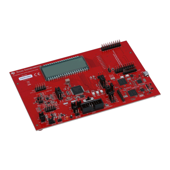
This guide is a reference to the different hardware configurations available with the
Ultrasonic Sensing Evaluation Module
configurations and pinouts, and communication interfaces.
..........................................................................................................................
1
1.1
1.2
2
2.1
2.2
2.3
2.4
2.5
..........................................................................................................................
3
4
4.1
4.2
4.3
..................................................................................................................
5
Trademarks
BoosterPack is a trademark of Texas Instruments.
All other trademarks are the property of their respective owners.
SLAU764 - January 2019
Submit Documentation Feedback
EVM430-FR6043 hardware guide
(EVM430-FR6043). These configurations include power, header
..........................................................................................................
......................................................................................................
.........................................................................................................
...............................................................................................
................................................................................................
.................................................................................................................
....................................................................................................
..........................................................................................................
......................................................................................................
.........................................................................................................
.........................................................................................................
Copyright © 2019, Texas Instruments Incorporated
Contents
..................................................................
EVM430-FR6043 hardware guide
User's Guide
SLAU764 - January 2019
MSP430FR6043
2
2
3
5
5
6
7
8
8
10
11
11
11
11
12
1
Advertisement
Table of Contents

Related Manuals for Texas Instruments EVM430-FR6043


Summary of Contents for Texas Instruments EVM430-FR6043
-
Page 1: Table Of Contents
SLAU764 – January 2019 EVM430-FR6043 hardware guide This guide is a reference to the different hardware configurations available with the MSP430FR6043 Ultrasonic Sensing Evaluation Module (EVM430-FR6043). These configurations include power, header configurations and pinouts, and communication interfaces. Contents .......................... Power ...................... -
Page 2: Power
Power The USB or an external power supply (for example, a battery or a bench supply) can supply power to the EVM430-FR6043. Jumper and switch configurations set the power source for the MSP430FR6043 microcontroller (MCU). USB Power To use USB as the power source, set the S5 (POW_SEL) switch to the middle position (ezFET) (see Figure Figure 1. -
Page 3: External Power
J3. If the circuit does not use a regulator (which is optional), the operational supply voltage range is 1.8 V to 3.6 V. If communicating through USB, set GND on J2 and the communication jumpers on J1. Figure 3. External Power SLAU764 – January 2019 EVM430-FR6043 hardware guide Submit Documentation Feedback Copyright © 2019, Texas Instruments Incorporated... - Page 4 To measure current consumption, remove the J32 jumper and place an ammeter across the header (see Figure 4). When current measurements are not being performed, make sure to set this jumper. Figure 4. Current Measurement Header EVM430-FR6043 hardware guide SLAU764 – January 2019 Submit Documentation Feedback Copyright © 2019, Texas Instruments Incorporated...
-
Page 5: Header Connections
Provides power to the AFE transmit circuitry. Can be used for power measurement. Provides power to the AFE receive circuitry. Can be used for power measurement. SLAU764 – January 2019 EVM430-FR6043 hardware guide Submit Documentation Feedback Copyright © 2019, Texas Instruments Incorporated... -
Page 6: Transducer Headers
You can connect two transducers to the board on J5 and J6. The PCB silkscreen shows signal (X1 or X2) and ground (GND) for each transducer. Figure 5. Transducer Header EVM430-FR6043 hardware guide SLAU764 – January 2019 Submit Documentation Feedback Copyright © 2019, Texas Instruments Incorporated... -
Page 7: Connectors For Boosterpack Plug-In Modules
N.C. N.C. GPIO N.C. N.C. N.C. N.C. N.C. N.C. SPI_MOSI SPI_CLK N.C. N.C. SPI_MISO N.C. N.C. N.C. N.C. N.C. N.C. N.C. N.C. N.C. GPIO SLAU764 – January 2019 EVM430-FR6043 hardware guide Submit Documentation Feedback Copyright © 2019, Texas Instruments Incorporated... -
Page 8: Jtag
If external power is used, set the switch to the top position (External). Figure 7. JTAG Header Communications The EVM430-FR6043 supports UART, I C, and Spy-Bi-Wire interfaces. J3 connects JTAG TX and RX (UART). To use this interface with the on-board eZ-FET circuit, place... - Page 9 J1 provides a connection between the MSP430FR6043 MCU and the high-speed USB HID interface. To enable I C, put jumpers on the J1 COMM_SDA, COMM_SCL, and COMM_IRQ pins (see Figure 10). Figure 10. I C Jumpers SLAU764 – January 2019 EVM430-FR6043 hardware guide Submit Documentation Feedback Copyright © 2019, Texas Instruments Incorporated...
-
Page 10: Lcd
12). Use a small flathead screwdriver to adjust the resistance of R3 and monitor the contrast on the display. Figure 12. LCD Contrast Control EVM430-FR6043 hardware guide SLAU764 – January 2019 Submit Documentation Feedback Copyright © 2019, Texas Instruments Incorporated... -
Page 11: Afe Configuration
AFE Configuration www.ti.com AFE Configuration The EVM430-FR6043 includes circuitry for additional amplification and to filter. The following sections describe how to configure this AFE. Power Source To use the same voltage source as the MCU, set JP3. To use an external voltage source, remove the... -
Page 12: References
References MSP430FR6043-based ultrasonic gas flow meter quick start guide MSP430FR604x, MSP430FR504x ultrasonic sensing MSP430™ microcontrollers for gas and water flow metering applications data sheet EVM430-FR6043 hardware guide SLAU764 – January 2019 Submit Documentation Feedback Copyright © 2019, Texas Instruments Incorporated... - Page 13 TI products. TI’s provision of these resources does not expand or otherwise alter TI’s applicable warranties or warranty disclaimers for TI products. TI objects to and rejects any additional or different terms you may have proposed. IMPORTANT NOTICE Mailing Address: Texas Instruments, Post Office Box 655303, Dallas, Texas 75265 Copyright © 2022, Texas Instruments Incorporated...
Need help?
Do you have a question about the EVM430-FR6043 and is the answer not in the manual?
Questions and answers