
Subscribe to Our Youtube Channel
Related Manuals for Texas Instruments EK-TM4C123GXL


Summary of Contents for Texas Instruments EK-TM4C123GXL
- Page 1 EK-TM4C123GXL Firmware Development Package USER’S GUIDE SW-EK-TM4C123GXL-UG-2.1.3.156 Copyright © 2012-2016 Texas Instruments Incorporated...
-
Page 2: Copyright
Thumb are registered trademarks and Cortex is a trademark of ARM Limited. Other names and brands may be claimed as the property of others. Please be aware that an important notice concerning availability, standard warranty, and use in critical applications of Texas Instruments semicon- ductor products and disclaimers thereto appears at the end of this document. -
Page 3: Table Of Contents
..........EK-TM4C123GXL Quickstart Application (qs-rgb) . - Page 4 Table of Contents July 25, 2016...
-
Page 5: Introduction
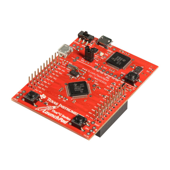
Introduction Introduction The Texas Instruments® Tiva™ C Series EK-TM4C123GXL evaluation board is a low cost platform that can be used for software development and to prototype a hardware design. It contains a Tiva C Series ARM® Cortex™-M4F-based microcontroller, a USB device port, two push buttons, and a RGB LED that can be used to exercise the peripherals on the microcontroller. - Page 6 Introduction July 25, 2016...
-
Page 7: Example Applications
These applications are intended for demonstration and as a starting point for new applications. There is an IAR workspace file (ek-tm4c123gxl.eww) that contains the peripheral driver li- brary project, USB library project, and all of the board example projects, in a single, easy to use workspace for use with Embedded Workbench version 6. -
Page 8: Gpio Jtag Recovery (Gpio_Jtag)
Example Applications A Semaphore to guard the resource, UART, from access by multiple tasks at the same time. A non-blocking FreeRTOS Delay to put the tasks in blocked state when they have nothing to additional details FreeRTOS, refer FreeRTOS page http://www.freertos.org/ GPIO JTAG Recovery (gpio_jtag) This example demonstrates changing the JTAG pins into GPIOs, aint32_t with a mechanism to... -
Page 9: Project Zero (Project0)
EK-TM4C123GXL Quickstart Application (qs-rgb) A demonstration of the Tiva C Series LaunchPad (EK-TM4C123GXL) capabilities. Press and/or hold the left button to traverse towards the red end of the ROYGBIV color spectrum. Press and/or hold the right button to traverse toward the violet end of the ROYGBIV color spectrum. -
Page 10: Uart Echo (Uart_Echo)
Example Applications 2.11 UART Echo (uart_echo) This example application utilizes the UART to echo text. The first UART (connected to the USB debug virtual serial port on the evaluation board) will be configured in 115,200 baud, 8-n-1 mode. All characters received on the UART are transmitted back to the UART. 2.12 uDMA (udma_demo) This example application demonstrates the use of the uDMA controller to transfer data between... -
Page 11: Usb Serial Device (Usb_Dev_Serial)
Example Applications 2.15 USB Serial Device (usb_dev_serial) This example application turns the evaluation kit into a virtual serial port when connected to the USB host system. The application supports the USB Communication Device Class, Abstract Control Model to redirect UART0 traffic to and from the USB host system. Assuming you installed TivaWare C Series in the default directory, a driver information (INF) file for use with Windows XP, Windows Vista and Windows7 can be found in C:/ti/TivaWare-for- C-Series/windows_drivers. - Page 12 Example Applications July 25, 2016...
-
Page 13: Buttons Driver
TM4C123GXL evaluation board. The driver provides a function to initialize all the hardware required for the buttons, and features for debouncing and querying the button state. This driver is located in examples/boards/ek-tm4c123gxl/drivers, with buttons.c con- taining the source code and buttons.h containing the API declarations for use by applications. -
Page 14: Programming Example
Buttons Driver Prototype: uint8_t ButtonsPoll(uint8_t * pui8Delta, uint8_t * pui8RawState) Parameters: pui8Delta points to a character that will be written to indicate which button states changed since the last time this function was called. This value is derived from the debounced state of the buttons. -
Page 15: Rgb Led Driver
Programming Example ................. . . 19 Introduction The RGB LED driver provides a simple interface to control the RGB LED on the EK-TM4C123GXL. The driver provides a function to initialize the timers and GPIO for the RGB. It also provides features for controlling the color and intensity of the LED. - Page 16 RGB LED Driver Returns: None. 4.2.1.2 RGBBlinkRateSet Sets the blink rate of the RGB Led Prototype: void RGBBlinkRateSet(float fRate) Parameters: fRate is the blink rate in hertz. Description: This function controls the blink rate of the RGB LED in auto blink mode. to enable blinking pass a non-zero floating pointer number.
- Page 17 RGB LED Driver Parameters: pui32RGBColor points to a three element array representing the relative intensity of each color. Red is element 0, Green is element 1, Blue is element 2. 0x0000 is off. 0xFFFF is fully on. Description: This function should be called by the application to set the color of the RGB LED. Returns: None.
- Page 18 RGB LED Driver Parameters: ui32Enable enables RGB immediately if set. Description: This function must be called during application initialization to configure the GPIO pins to which the LEDs are attached. It enables the port used by the LEDs and configures each color’s Timer. It optionally enables the RGB LED by configuring the GPIO pins and starting the timers.
-
Page 19: Programming Example
RGB LED Driver Programming Example The following example shows how to use the rgb driver to initialize the RGB LED. unsigned long ulColors[3]; // Initialize the rgb driver. RGBInit(0); // Set the intensity level from 0.0f to 1.0f RGBIntensitySet(0.3f); // Initialize the three color values. ulColors[BLUE] = 0x00FF;... -
Page 20: Important Notice
IMPORTANT NOTICE Texas Instruments Incorporated and its subsidiaries (TI) reserve the right to make corrections, enhancements, improvements and other changes to its semiconductor products and services per JESD46, latest issue, and to discontinue any product or service per JESD48, latest issue. Buyers should obtain the latest relevant information before placing orders and should verify that such information is current and complete.
Need help?
Do you have a question about the EK-TM4C123GXL and is the answer not in the manual?
Questions and answers