
Related Manuals for Texas Instruments TM4C Series


Summary of Contents for Texas Instruments TM4C Series
- Page 1 TM4C Series TM4C129E Crypto Connected LaunchPad Evaluation Kit EK-TM4C129EXL User's Guide Literature Number: SPMU372A September 2015 – Revised October 2016...
-
Page 2: Table Of Contents
Programming the Crypto Connected LaunchPad ........................References ........................References ..................PCB Layout and Bill of Materials ..................... Component Locations ......................Bill of Materials ......................... Schematic Contents SPMU372A – September 2015 – Revised October 2016 Submit Documentation Feedback Copyright © 2015–2016, Texas Instruments Incorporated... - Page 3 .......................... Revision History SPMU372A – September 2015 – Revised October 2016 Contents Submit Documentation Feedback Copyright © 2015–2016, Texas Instruments Incorporated...
- Page 4 List of Figures ............1-1. TM4C Series Crypto Connected LaunchPad Evaluation Board ..........2-1. TM4C Crypto Connected LaunchPad Evaluation Board Block Diagram ....................2-2. Default Jumper Locations ..........A-1. Crypto Connected LaunchPad Dimensions and Component Locations List of Tables ..................
-
Page 5: Board Overview
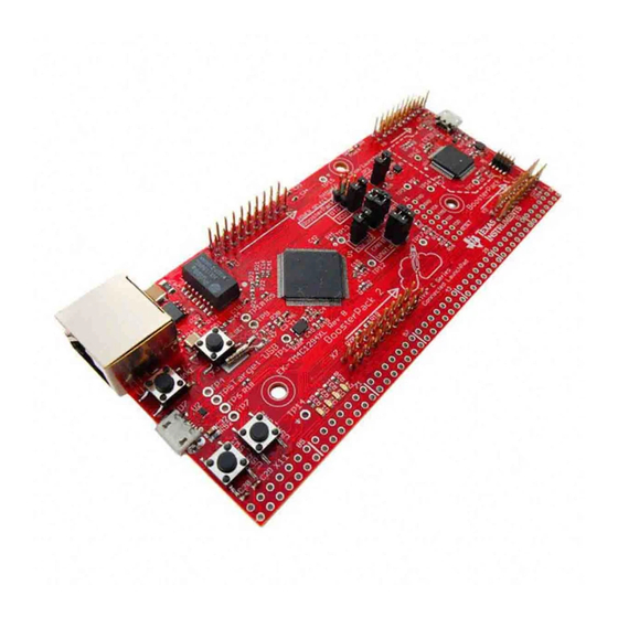
Chapter 1 SPMU372A – September 2015 – Revised October 2016 Board Overview The TM4C Series TM4C129E Crypto Connected LaunchPad™ Evaluation Board (EK-TM4C129EXL) is a low-cost evaluation platform for ARM Cortex -M4F-based microcontrollers. The Crypto Connected ® ® LaunchPad design highlights the TM4C129ENCPDT microcontroller with its on-chip crypto acceleration hardware, 10/100 Ethernet MAC and PHY, USB 2.0, hibernation module, motion control pulse-width... -
Page 6: Kit Contents
3. Take the first step towards developing your own applications. The Crypto Connected LaunchPad is supported by TivaWare™ for C Series. All the applications that work on TM4C series TM4C1294 Connected LaunchPad Evaluation Board (EK-TM4C1294XL) will work on the Crypto Connected LaunchPad. -
Page 7: Boosterpacks
The Crypto Connected LaunchPad provides an easy and inexpensive way to develop applications with the TM4C129ENCPDT microcontroller. BoosterPacks are add-on boards that follow a pin-out standard created by Texas Instruments. The TI and third-party ecosystem of BoosterPacks greatly expands the peripherals and potential applications that you can easily explore with the Crypto Connected LaunchPad. - Page 8 Specifications www.ti.com Board Overview SPMU372A – September 2015 – Revised October 2016 Submit Documentation Feedback Copyright © 2015–2016, Texas Instruments Incorporated...
-
Page 9: Hardware Description
The out of the box application automatically connects to https://ti.exosite.com when an internet connection is provided through the RJ45 Ethernet jack on the evaluation board. SPMU372A – September 2015 – Revised October 2016 Hardware Description Submit Documentation Feedback Copyright © 2015–2016, Texas Instruments Incorporated... -
Page 10: Ethernet Connectivity
PHY control and data signals are provided on the breadboard expansion header X11. 2.1.5 Motion Control The Crypto Connected LaunchPad includes the TM4C Series Motion Control PWM technology, featuring a PWM module capable of generating eight PWM outputs. The PWM module provides a great deal of... -
Page 11: User Switches And Led's
PF0, which can be controlled by user’s software or the integrated Ethernet module of the microcontroller. A power LED is also provided to indicate that 3.3 V power is present on the board. SPMU372A – September 2015 – Revised October 2016 Hardware Description Submit Documentation Feedback Copyright © 2015–2016, Texas Instruments Incorporated... -
Page 12: Boosterpacks And Headers
U2CTS T4CCP1 USB0PFLT SSI2XDAT2 Analog U2Rx I2C6SCL T3CCP0 USB0EPEN SSI0XDAT2 EPI0S8 A out TMPR3 U0CTS T4CCP0 A out TMPR2 U0DCD T4CCP1 Hardware Description SPMU372A – September 2015 – Revised October 2016 Submit Documentation Feedback Copyright © 2015–2016, Texas Instruments Incorporated... - Page 13 I2C7SDA T0CCP1 SSI2XDAT0 SPI MISO AIN15 I2C7SCL T0CCP0 SSI2XDAT1 GPIO U1DCD U2RTS EPI0S29 GPIO U1DSR U2CTS EPI0S30 GPIO U0DTR USB0NXT EPI0S29 SPMU372A – September 2015 – Revised October 2016 Hardware Description Submit Documentation Feedback Copyright © 2015–2016, Texas Instruments Incorporated...
-
Page 14: Boosterpack 2
Using the jumpers JP4 and JP5, Controller Area Network (CAN) digital receive and transmit signals can be optionally routed to the BoosterPack 2 interface. The location of these signals is consistent with the CAN interface on the TM4C Series TM4C123G LaunchPad and the Stellaris LM4F120 LaunchPad. - Page 15 SSI0Fss SPI MISO SSI3XDAT1 EPI0S23 U4Rx I2C8SCL T1CCP0 SSI0Clk GPIO U1CTS U0DCD USB0DIR EPI0S30 GPIO SSI3Fss EPI0S21 GPIO TMPR1 U0DSR T5CCP0 SPMU372A – September 2015 – Revised October 2016 Hardware Description Submit Documentation Feedback Copyright © 2015–2016, Texas Instruments Incorporated...
-
Page 16: Breadboard Connection
EPI0S8 U2Tx I2C6SDA T3CCP1 USB0PFLT USB0EPEN SSI0XDAT3 EPI0S9 I2C1SDA M0PWM5 EPI0S10 I2C1SCL EN0PPS M0PWM4 EPI0S11 T3CCP1 EPI0S12 T3CCP0 EPI0S13 T2CCP1 EPI0S14 Hardware Description SPMU372A – September 2015 – Revised October 2016 Submit Documentation Feedback Copyright © 2015–2016, Texas Instruments Incorporated... - Page 17 USB0D5 EPI0S33 U1DTR U3RTS I2C2SDA EPI0S34 U1RI U3CTS I2C2SCL EPI0S35 U1RTS U1CTS U1DCD U2RTS EPI0S29 U1DSR U2CTS EPI0S30 U1Rx DIVSCLK WAKE SPMU372A – September 2015 – Revised October 2016 Hardware Description Submit Documentation Feedback Copyright © 2015–2016, Texas Instruments Incorporated...
-
Page 18: X11 Breadboard Adapter Even-Numbered Pad Gpio And Signal Muxing
SSI3XDAT2 U6Tx SSI3XDAT3 USB0ID U1Rx I2C5SCL T4CCP0 CAN1Rx USB0VBUS U1Tx I2C5SDA T4CCP1 CAN1Tx EN0LED1 M0FAULT0 SSI3XDAT2 TRD3 EN0LED0 M0PWM0 SSI3XDAT1 TRD2 Hardware Description SPMU372A – September 2015 – Revised October 2016 Submit Documentation Feedback Copyright © 2015–2016, Texas Instruments Incorporated... - Page 19 U3RTS U0DSR USB0D7 U3CTS I2C2SCL USB0D6 U3Rx U3Tx TMPR0 U0RI T5CCP1 TMPR1 U0DSR T5CCP0 TMPR2 U0DCD T4CCP1 TMPR3 U0CTS T4CCP0 RESET SPMU372A – September 2015 – Revised October 2016 Hardware Description Submit Documentation Feedback Copyright © 2015–2016, Texas Instruments Incorporated...
-
Page 20: Other Headers And Jumpers
USB host mode. This load switch also limits current to the BoosterPack and Breadboard adapter headers when the JP1 jumper is in the ICDI position. Hardware Description SPMU372A – September 2015 – Revised October 2016 Submit Documentation Feedback Copyright © 2015–2016, Texas Instruments Incorporated... -
Page 21: Low Power Modes
R40 must be installed to use an external debug adapter to program or debug the Crypto Connected LaunchPad. SPMU372A – September 2015 – Revised October 2016 Hardware Description Submit Documentation Feedback Copyright © 2015–2016, Texas Instruments Incorporated... -
Page 22: External Debugger
In the default configuration, UART0 maps to the virtual COM port of the ICDI. In the CAN jumper configuration, UART2 maps to the virtual COM port of the ICDI. Hardware Description SPMU372A – September 2015 – Revised October 2016 Submit Documentation Feedback Copyright © 2015–2016, Texas Instruments Incorporated... -
Page 23: Software Development
Crypto Connected LaunchPad evaluation board. Example applications provided for the TM4C Series TM4C1294 Connected LaunchPad and examples paired with selected BoosterPacks will work with the Crypto Connected LaunchPad. -
Page 24: Source Code
® • Generic GNU C Compiler • Texas Instruments' Code Composer Studio™ IDE Download evaluation versions of these tools from the Tools & Software section of www.ti.com/tiva. Due to code size restrictions, the evaluation tools may not build all example programs. A full license is necessary to re-build or debug all examples. -
Page 25: References
LM Flash Programmer Tool (http://www.ti.com/lmflashprogrammer) • TPS73733 Low-Dropout Regulator with Reverse Current Protection (http://www.ti.com/product/tps79733) • Texas Instruments Code Composer Studio website (http://www.ti.com/ccs) • Tiva TM4C129ENCPDT Microcontroller Data Sheet (SPMS441) • Build Your Own BoosterPack information regarding the BoosterPack standard (http://www.ti.com/byob) •... -
Page 26: Pcb Layout And Bill Of Materials
Figure A-1. Crypto Connected LaunchPad Dimensions and Component Locations PCB Layout and Bill of Materials SPMU372A – September 2015 – Revised October 2016 Submit Documentation Feedback Copyright © 2015–2016, Texas Instruments Incorporated... -
Page 27: Bill Of Materials
Resistor, 1M OH, R34, R52 Panasonic ERJ-3GEYJ105V 1/10W, 5% 0603 SMD Resistor, 51 Ω, Panasonic ERJ-2GEJ510X 1/10W, 5%, 0402 SPMU372A – September 2015 – Revised October 2016 PCB Layout and Bill of Materials Submit Documentation Feedback Copyright © 2015–2016, Texas Instruments Incorporated... - Page 28 Crystal 16 MHz 3.2 x 2.5 mm NX3225GA-16.000M-STD-CRG-2 4 pin Citizen Finetech Crystal, 32.768 KHz radial CAN CMR200T-32.768KDZY-UT Miyota PCB Layout and Bill of Materials SPMU372A – September 2015 – Revised October 2016 Submit Documentation Feedback Copyright © 2015–2016, Texas Instruments Incorporated...
- Page 29 Right angle extended, Samtec TSW-149-09-F-S-RE 1 x 49 0.100 pitch. Valvano style breadboard X11B Samtec TSW-149-08-F-S-RA header SPMU372A – September 2015 – Revised October 2016 PCB Layout and Bill of Materials Submit Documentation Feedback Copyright © 2015–2016, Texas Instruments Incorporated...
-
Page 30: Schematic
Appendix B SPMU372A – September 2015 – Revised October 2016 Schematic This section contains the complete schematics for the TM4C Series TM4C129E Crypto Connected LaunchPad. • Microcontroller, USB, Buttons, and LED's • BoosterPack connectors • Breadboard connector • Ethernet and Ethernet LED's •... - Page 31 NOTE: Page numbers for previous revisions may differ from page numbers in the current version. Changes from Original (September 2015) to A Revision ....................Page ..............• GLOBAL: Updated/Changed all instances of "UART4" to "UART2" SPMU372A – September 2015 – Revised October 2016 Revision History Submit Documentation Feedback Copyright © 2015–2016, Texas Instruments Incorporated...
- Page 32 STANDARD TERMS FOR EVALUATION MODULES Delivery: TI delivers TI evaluation boards, kits, or modules, including any accompanying demonstration software, components, and/or documentation which may be provided together or separately (collectively, an “EVM” or “EVMs”) to the User (“User”) in accordance with the terms set forth herein.
- Page 33 FCC Interference Statement for Class B EVM devices NOTE: This equipment has been tested and found to comply with the limits for a Class B digital device, pursuant to part 15 of the FCC Rules. These limits are designed to provide reasonable protection against harmful interference in a residential installation.
- Page 34 【無線電波を送信する製品の開発キットをお使いになる際の注意事項】 開発キットの中には技術基準適合証明を受けて いないものがあります。 技術適合証明を受けていないもののご使用に際しては、電波法遵守のため、以下のいずれかの 措置を取っていただく必要がありますのでご注意ください。 1. 電波法施行規則第6条第1項第1号に基づく平成18年3月28日総務省告示第173号で定められた電波暗室等の試験設備でご使用 いただく。 2. 実験局の免許を取得後ご使用いただく。 3. 技術基準適合証明を取得後ご使用いただく。 なお、本製品は、上記の「ご使用にあたっての注意」を譲渡先、移転先に通知しない限り、譲渡、移転できないものとします。 上記を遵守頂けない場合は、電波法の罰則が適用される可能性があることをご留意ください。 日本テキサス・イ ンスツルメンツ株式会社 東京都新宿区西新宿6丁目24番1号 西新宿三井ビル 3.3.3 Notice for EVMs for Power Line Communication: Please see http://www.tij.co.jp/lsds/ti_ja/general/eStore/notice_02.page 電力線搬送波通信についての開発キットをお使いになる際の注意事項については、次のところをご覧ください。http:/ /www.tij.co.jp/lsds/ti_ja/general/eStore/notice_02.page 3.4 European Union 3.4.1 For EVMs subject to EU Directive 2014/30/EU (Electromagnetic Compatibility Directive): This is a class A product intended for use in environments other than domestic environments that are connected to a low-voltage power-supply network that supplies buildings used for domestic purposes.
- Page 35 Notwithstanding the foregoing, any judgment may be enforced in any United States or foreign court, and TI may seek injunctive relief in any United States or foreign court. Mailing Address: Texas Instruments, Post Office Box 655303, Dallas, Texas 75265 Copyright © 2017, Texas Instruments Incorporated...
- Page 36 IMPORTANT NOTICE FOR TI DESIGN INFORMATION AND RESOURCES Texas Instruments Incorporated (‘TI”) technical, application or other design advice, services or information, including, but not limited to, reference designs and materials relating to evaluation modules, (collectively, “TI Resources”) are intended to assist designers who are developing applications that incorporate TI products;...
Need help?
Do you have a question about the TM4C Series and is the answer not in the manual?
Questions and answers