Table of Contents
Advertisement
Quick Links
GTC-520F
Instruction Manual
Headquarters / Engineering research laboratory :
23 Gunpo Advance d Industry 1-ro(Bugok-dong), Gunpo-si, Gyeonggi-do
Tel +82-31-490-0800 Fax +82-31-490-0801
Yeongnam business office / Plant :
55 Gonghangap-gil 85beon-gil, Gangseogu, Busan Metropolitan City
Tel +51-973-8518 Fax +51-973-8519
E-mail : info@gastron.com
www.gastron.com
Read in detail for correct use.
Advertisement
Table of Contents

Related Manuals for GASTRON GTC-520F


Summary of Contents for GASTRON GTC-520F
- Page 1 Headquarters / Engineering research laboratory : 23 Gunpo Advance d Industry 1-ro(Bugok-dong), Gunpo-si, Gyeonggi-do Tel +82-31-490-0800 Fax +82-31-490-0801 Yeongnam business office / Plant : 55 Gonghangap-gil 85beon-gil, Gangseogu, Busan Metropolitan City Tel +51-973-8518 Fax +51-973-8519 E-mail : info@gastron.com www.gastron.com Read in detail for correct use.
- Page 2 Gas & Flame We sincerely thank you for purchasing the product of Gastron Co. Ltd. Our Gastron Co.Ltd. is a company specialized in Gas Detector & Gas Monitoring System and have been Detection System recognized by many customers for the best quality and use convenience. We always seek to help our customers to find the product they need and we continuously research to develop gas detectors that satisfies our customers.
-
Page 3: Table Of Contents
GTC-520F Contents Contents www.gastron.com Instruction Manual 04_05 Overview · · · · · · · · · · · · · · · · · · · · · · · · · · · · · · · · · · · · · · · · · · · · · · · · · · · · · · · · · · · · · · · · · · · · · · · · · · · · · · · · · · · · · · · · · ·... -
Page 4: Overview
06_07 3.1. Basic Specifications Receiver of GTC-520F is a receiver with high-performance A/D converter and micro-processor and has various functions built-in. The receiver of GTC-520F is a stand-alone type that is connected to one detector and is protected ITEMS SPECIFICATION by a case made of ABS material. -
Page 5: Electrical Specifications (Standard Type)
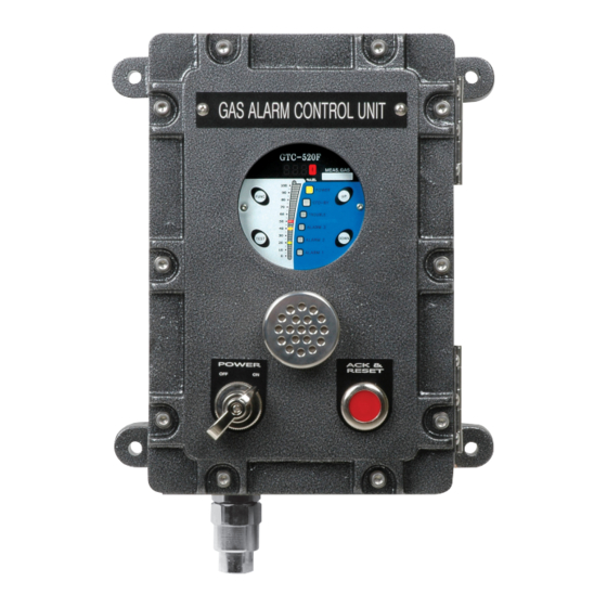
Cable Connection Length RS485 1000m EMC Protection: 3.4. Environmental Specifications ITEMS SPECIFICATION Operation Temperature -20 to 60 ℃ Storage Temperature -20 to 60 ℃ Operation Humidity 5 to 99% RH (Non-condensing) Pressure Range 90 to 110KPa [Figure 1. GTC-520F Components]... - Page 6 When power is inputted, the power LED lights on. Stand-by LED When the detector is in stand-by mode, STD-BY LED blinks. [Table 1. GTC-520F Description on configuration] When power is inputted, the power LED lights on. Trouble LED When the detector is in stand-by mode, STD-BY LED blinks.
-
Page 7: Installation
White Cable Red Cable Red Cable External Reset S/W + Terminal. [Figure 2. GTC-520F Power Configuration] When + and - terminals short, alarm reset function operates. RESET External Reset S/W - Terminal ■ When it is desired to use DC24V, a separate request must be made when ordering the product. When the product... -
Page 8: Relay Terminal Configuration
GTC-520F 5. Installation 5. Installation www.gastron.com Instruction Manual 14_15 5.3. Relay Terminal Configuration 5.4. 3-wire type Gas detector Connection Method ■ Using CN5 terminal, it consists of 3 SPDT-type Alarm relay and 1 SPDT-type Trouble relay. ■ When the gas detector has 3-wire (V+, mA, V-) for power and ■... -
Page 9: Operation Method
- This function enables testing at channel unit without injecting gas to the detector sensor. It can set an arbitrary concentration when the user presses "Test" S/W and alarm function operates - After GTC-520F power turns ON, the current firm ware version is displayed. normally with a user-defined concentration. -
Page 10: Setting Table
GTC-520F 6. Operation Method 6. Operation Method www.gastron.com Instruction Manual 18_19 6.5. Operation Setting LEVEL1 LEVEL2 PARAMETER DEFAULT (Maintenance-Level) 0 ~ Full range 6.5.1. Setting Table (Under) ON / OFF Option MODE (Engineering) ON / OFF LEVEL1 LEVEL2 PARAMETER DEFAULT... -
Page 11: Program Mode
GTC-520F 6. Operation Method 6. Operation Method www.gastron.com Instruction Manual 20_21 6.5.2. PROGRAM MODE ■ After setting a password, move to "UP" S/W or "DOWN" S/W then press "FUNC" S/W to enter the mode. - High scale changes a set value according to measuring range. Scale value increases or decreases upon pressing "UP"... -
Page 12: Alarm Mode
GTC-520F 6. Operation Method 6. Operation Method www.gastron.com Instruction Manual 22_23 6.5.3. ALARM Mode - A message indicating completion of setting is displayed as "End" for 2 sec then it returns to gas ■ After setting a password, move to "UP" S/W or "DOWN" S/W then press "FUNC" S/W to enter the mode. - Page 13 GTC-520F 6. Operation Method 6. Operation Method www.gastron.com Instruction Manual 24_25 - Mode that sets external warning lights to operate with a desired alarm. - When "FUNC" S/W is pressed, it enters Alarm Lamp setting mode. - When "RESET" S/W is pressed, it enters Alarm Setting Mode.
-
Page 14: Option Mode (Option Setting)
■ In option mode, most settings are factory preset, therefore, this function should not be adjusted. the next item. When it is unavoidable, the user must seek help from Gastron to adjust. - When "RESET" S/W is pressed, it enters Alarm Setting Mode. -
Page 15: Test Mode
GTC-520F 6. Operation Method 6. Operation Method www.gastron.com Instruction Manual 28_29 6.5.5. Test Mode - For measurement display, it displays raw data from -XXXX ~ +YYYY. - When "FUNC" S/W is pressed, it enters "Under" setting mode. ■ After setting a password, move to "UP" S/W or "DOWN" S/W then press "FUNC" S/W to enter the mode. -
Page 16: 485 Setting Mode
GTC-520F 6. Operation Method 6. Operation Method www.gastron.com Instruction Manual 30_31 6.5.6. 485 Setting Mode It is mA Output Signal Test Mode. ■ After setting a password, move to "UP" S/W or "DOWN" S/W then press "FUNC" S/W to enter the mode. -
Page 17: Maintenance Mode
GTC-520F 6. Operation Method 6. Operation Method www.gastron.com Instruction Manual 32_33 6.5.7. Maintenance Mode ■ Pressing both "RESET" and "TEST" S/W for 2 sec or longer in gas concentration display mode enters Maintenance mode. ■ "RESET" S/W must be pressed in Maintenance mode to return to gas concentration display mode. -
Page 18: Factory Initialization Mode
■ Factory initial is a mode that resets the data to the originafla ctory setting. ■ In factory initialization mode, most settings are factory preset, therefore, this function should not be adjusted. When it is unavoidable, the user must seek help from Gastron to adjust. - Press "FUNC" S/W tp enter. -
Page 19: Interface Configuration
Calibration Mode Status BIT6 Reserved BIT7 Toggle Bit (Bit reversal in 2 sec interval) External Test BIT0~7 Gas Detector Test Mode Setting External Reset BIT0~7 Exit Gas Detector Test Mode [Table 5. RS485 MODBUS Address Configuration] [Figure 7. GTC-520F Drawing]... -
Page 20: Precautions Before Installation
GTC-520F 9. Precautions before Installation 9. Precautions before Installation www.gastron.com Instruction Manual 38_39 9.1. Selecting a Place for Installation (Occupational Health & Safety Act Data) ■ During wiring work, use explosion-proof cable gland at cable inlet or tightly seal cable conduit during metal cable wiring construction to prevent spread of flames in case of explosion or movement of gas, etc. -
Page 21: Revision Record
GTC-520F 10. Revision record www.gastron.com Instruction Manual 40_41 VERSION CONTENTS DATE Manual Initial Revision 2011. 08. 25 Changed Main PCB Layout and Added function 2014. 01. 15 Corrected Program Mode Function 2015. 04. 27 Changed Font 2016. 09. 23 Changed Explosion-proof Equipment Cable Entry Installation Regulation 45 cm → 50 mm...
Need help?
Do you have a question about the GTC-520F and is the answer not in the manual?
Questions and answers