Table of Contents
Advertisement
Quick Links
GTC-520A
Instruction Manual
Headquarters / Engineering research laboratory :
23 Gunpo Advance d Industry 1-ro(Bugok-dong), Gunpo-si, Gyeonggi-do
Tel +82-31-490-0800 Fax +82-31-490-0801
Yeongnam business office / Plant :
55 Gonghangap-gil 85beon-gil, Gangseogu, Busan Metropolitan City
Tel +51-973-8518 Fax +51-973-8519
E-mail : info@gastron.com
www.gastron.com
Read in detail for correct use.
Advertisement
Table of Contents

Subscribe to Our Youtube Channel
Related Manuals for GASTRON GTC-520A


Summary of Contents for GASTRON GTC-520A
- Page 1 Headquarters / Engineering research laboratory : 23 Gunpo Advance d Industry 1-ro(Bugok-dong), Gunpo-si, Gyeonggi-do Tel +82-31-490-0800 Fax +82-31-490-0801 Yeongnam business office / Plant : 55 Gonghangap-gil 85beon-gil, Gangseogu, Busan Metropolitan City Tel +51-973-8518 Fax +51-973-8519 E-mail : info@gastron.com www.gastron.com Read in detail for correct use.
- Page 2 Gas detectors satisfying customers. From now on, solve all anguishes concerning Gas detector with the products of Gastron Co. Ltd, We Gastron Co. will take a responsibility and give you satisfaction.
-
Page 3: Table Of Contents
GTC-520A Contents Contents www.gastron.com Instruction Manual 04_05 1. Overview ······································································································································································ 6.5.8. Factory initialization function (Factory Initial) ····················································································· 6.5.9. Initialization function for calibration data(Calibration Initial) ···························································· 2. Features ········································································································································································ 7. Interface configuration ·············································································································································· 3. Specifications ······························································································································································· 7.1. MODBUS RS485 ····················································································································································· 3.1. Basic Specifications ············································································································································ 7.1.1. Interface setting ······································································································································ 3.2. Mechanical Specifications ·································································································································... -
Page 4: Overview
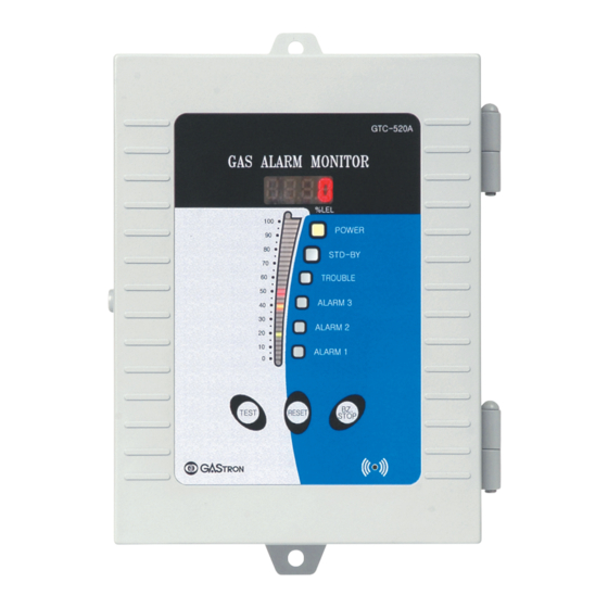
MODBUS RS485 Board Body(Transmitter) 2Year Warranty GTC-520A stand-alone type receiver unit displays with audio signal (Buzzer) and audio signal (Alarm LED) and Sensor 1Year has functions of holding the maximum measured value upon occurrence of alarm. GTC-520A receiver unit allows remote control for alarm clearing, and has output (SPDT contact) for the alarm so that it can perform the function of interlocking control. -
Page 5: Electrical Specifications (Standard Type)
GTC-520A 3. Specifications 4. Name and description of each part www.gastron.com Instruction Manual 08_09 3.3. Electrical Specifications (Standard Type) ITEMS SPECIFICATION Absolute min: AC 90V Input Voltage(AC Type/Standard) Nominal: AC 220V Absolute max: AC 250V Absolute min: Input Voltage(DC Type) Nominal: ※ Customer supplied PSU must meet requirements... - Page 6 Alarm 1 LED is lighted upon occurrence of 1st alarm. Alarm1 LED [Table 1. Description on configuration of GTC-520A] Alarm 1LED is lighted when 1st alarm is reached upon execution of test function. 3 Color bar graphic LED consecutively displays measured values and alarm setting values together with FND display.
-
Page 7: Installation
+ terminal and + terminal are short - circuited with - terminal. RESET - terminal of outside reset switch [Figure 2. Configuration of GTC-520A power supply] RS485 A terminal ( TRXD + or P) RS485 RS485 B terminal ( TRXD + or N) ■ When DC24V is to be used, a separate request should be made upon product ordering. When released as... -
Page 8: Configuration Of Relay Terminal
GTC-520A 5. Installation 5. Installation www.gastron.com Instruction Manual 14_15 5.3. Configuration of Relay terminal 5.4. How to connect 3-wire type Gas detector ■ By using CN5 terminal, it is configured with 3 ea of SPDT-type Alarm relay, and 1ea of SPDT -type Trouble relay. ■ When the gas detector is configured with 4-20mA output, connect ■ Alarm Lamp(LP) can be connected with DC outside warning light. with the Channel Unit by the method shown on the right side. ■ To use outside DC warning light or outside device, LP terminal outputs DC +24V power supply irrespective of ■ Connecting cable should be configured with shield cable of AC, DC power supply mode. -
Page 9: How To Operate
- This function allows testing in Channel Unit without gas injection in the detector sensor. When the user can set an arbitrary value for gas concentration by pushing "Test" S/W, while - When the power supply for GTC-520A is turned ON, the current Firm Ware Version is displayed. Alarm Function is normally operated with the concentration value designated by the user. -
Page 10: Setting Table
GTC-520A 6. How to operate 6. How to operate www.gastron.com Instruction Manual 18_19 6.5. Setting for operation LEVEL1 LEVEL2 PARAMETER DEFAULT (Maintenance-Level) 0 ~ Full range 6.5.1. Setting Table (Under) ON / OFF (Engineering) ON / OFF LEVEL1 LEVEL2 PARAMETER... -
Page 11: Program Mode
GTC-520A 6. How to operate 6. How to operate www.gastron.com Instruction Manual 20_21 6.5.2. PROGRAM MODE - High scale value is the function where the setting values are changed according to measuring range, and the scale value is increased or decreased whenever UP" S/W or "DOWN" S/W is pushed (Basic value100) - If "FUNC" S/W is pushed when the desired High scale value is displayed, the High scale value - When "FUNC" S/W is pushed, Program Mode is entered into. is set and the next item is entered into. -
Page 12: Alarm Mode
GTC-520A 6. How to operate 6. How to operate www.gastron.com Instruction Manual 22_23 6.5.3. ALARM Mode - Used when No.1 receiver unit receives mA value outputted from 1 unit of detector and No.2 receiver unit receives mA value outputted from the No.1 receiver unit. - Page 13 GTC-520A 6. How to operate 6. How to operate www.gastron.com Instruction Manual 24_25 - Mode setting for operation of outside warning light at the desired Alarm. - When "FUNC" S/W is pushed, the setting function for Alarm Lamp is entered into. - When "RESET" S/W is pushed, Alarm Setting Mode is returned to. ▼ ▲ - Mode for setting of Dead band value with operation of Alarm1. The value is increased or - Set by pushing "UP" S/W and "DOWN" S/W and using "FUNC" S/W in the desired Alarm.
- Page 14 GTC-520A 6. How to operate 6. How to operate www.gastron.com Instruction Manual 26_27 6.5.4. Option setting - Mode for change of Alarm1 contact output. "ON" and "OFF" modes are changed whenever "UP" ■ When "FUNC" S/W is pushed following moving by "UP" S/W or "DOWN" S/W after setting for Password, it can be S/W or "DOWN" S/W is pushed. entered into. - Alarm1 contact output mode has 2 types of "ON" and "OFF" where Alarm1 contact output is not operate in OFF mode, while it is operated in ON mode. ■ When 10sec passes after the last S/W operation in Optional setting function, the display state of gas - If "FUNC" S/W is pushed when the desired Alarm1 contact output mode is displayed, the Alarm1 concentration is automatically returned to.
- Page 15 GTC-520A 6. How to operate 6. How to operate www.gastron.com Instruction Manual 28_29 - For display of the measured value, display unprocessed data from -XXXX to +YYYY. - When "FUNC" S/W is pushed. The setting function for "Under" is entered into. - When "RESET" S/W is pushed, Option Setting Mode is returned to. - Setting is possible within the range of 0 ~ 20(%) by using "UP" S/W나 "DOWN" S/W. (This Mode is used only as Test mode, and is not used in actual fields) - If "FUNC" S/W is pushed when the desired value is displayed, the selection is set and the next...
-
Page 16: Test Mode
GTC-520A 6. How to operate 6. How to operate www.gastron.com Instruction Manual 30_31 6.5.5. Test Mode Test Mode for mA Output Signal . ■ When "FUNC" S/W is pushed after moving by "UP" S/W or "DOWN" S/W following setting for Password, it can be When "FUNC" S/W is pushed, the setting function for mA Output is entered into. entered into. When "RESET" S/W is pushed, Test Setting Mode is returned to. ■ When 10 sec passes after the last S/W operation in Test Mode function, the display state of gas concentration is automatically returned to. Test mode function allows testing without injection of sensor gas in the detector. The user can set - "ON/OFF state can be set by using "UP" S/W or "DOWN" S/W, and mA OUT function can be used... -
Page 17: 485 Setting Mode
GTC-520A 6. How to operate 6. How to operate www.gastron.com Instruction Manual 32_33 6.5.6. 485 Setting Mode 6.5.7. Maintenance Mode ■ When "FUNC" S/W is pushed after moving by "UP" S/W or "DOWN" S/W following setting for Password, it can be ■ When "RESET" and "TEST" S/W are pushed for more than 2 sec in the display state of gas concentration, the setting entered into. function for Maintenance is entered into. ■ When 10 sec passes after the last SW operation in 485 Mode function, the display state of gas concentration is ■ The display state of gas concentration is returned to only when "RESET" S/W is surely pushed in Maintenance mode returned to - Mode for selection of the function of outputting current input value and output value as the Mode for setting of 485 function. - Page 18 - When "RESET" S/W is pushed, the display state of gas concentration is returned to. ■ Since Factory Initial is mostly FACTORY setting functions , this function should not be operated. When inevitable, it should be operated with the support of Gastron Co. Ltd. Mode for initialization of the currently saved data to the existing data upon factory shipment. - Mode for setting of 20mA output current (Basic value 20.00).
- Page 19 GTC-520A 6. How to operate 7. Interface configuration www.gastron.com Instruction Manual 36_37 7.1. MODBUS RS485 It is the function using "FUNC" S/W, the cases for consecutive pushing of S/W occur. 7.1.1. Interface setting When "FUNC" S/W is operated upon Yes/no to prevent this, "1" -> "11" -> "111" -> "1111" is outputted in FND from the left side by the unit of 0.5s . ■ Data Format: RTU Upon selection of "YES" , initialization is completed, and the display state of gas concentration is ▼ ■ Baud rate: 9600 bps returned to. ■ Data bits: 8bits Upon selection of "no" , the display state of gas concentration is returned to without initialization.
- Page 20 7. Revision record www.gastron.com Instruction Manual 38_39 Version Contents Date Manual revised initially 2011. 08. 25 Main PCB Layout changed and functions added 2014. 01. 15 Program mode functions revised 2015. 04. 27 Font changed 2016. 09. 23 [Figure 7. Outline drawing for GTC-520A]...
Need help?
Do you have a question about the GTC-520A and is the answer not in the manual?
Questions and answers