
Related Manuals for ASROCK Rack AD2550R/U3S8


Summary of Contents for ASROCK Rack AD2550R/U3S8
- Page 1 AD2550R/U3S8 AD2550RA/U3S3 AD2550R/U3S3 AD2550R User Manual Version 1.1 Published September 2015 Copyright©2015 ASRock Rack INC. All rights reserved.
- Page 2 ASRock Rack has been advised of the possibility of such damages arising from any defect or error in the manual or product.
-
Page 3: Table Of Contents
Contents 1 Introduction ............5 1.1 Package Contents ..........5 1.2 Specifications ............6 1.3 Motherboard Layout ..........10 1.4 I/O Panel ............. 18 1.5 Block Diagram ............. 22 2 Installation ............26 2.1 Pre-installation Precautions ........ 26 2.2 Screw Holes ............26 2.3 Installation of Memory Modules (SO-DIMM) .. - Page 4 3 UEFI SETUP UTILITY ......... 37 3.1 Introduction ............37 3.1.1 UEFI Menu Bar ........... 37 3.1.2 Navigation Keys ......... 38 3.2 Main Screen ............39 3.3 Advanced Screen ..........40 3.3.1 CPU Configuration ........41 3.3.2 Chipset Configuration ......... 42 3.3.3 Storage Configuration ........
-
Page 5: Introduction
In case any modifications of this manual occur, the updated version will be available on ASRock Rack’s website without further notice. You may find the latest VGA cards and CPU support list on ASRock Rack’s website as well. ASRock Rack website http://www.ASRockRack.com... -
Page 6: Specifications
2 x SO-DIMM slots Capacity Support up to 4GB System Single Channel DDR3 memory technology Memory Type Supports DDR3 1066 DIMM Voltage 1.5V AD2550R/U3S8 1 slot (x1) AD2550RA/U3S3 1 slot (x1) Expansion PCIe x 16 Slot AD2550R/U3S3 1 slot (x1) AD2550R... - Page 7 ICH10R : 5* x SATA2 3.0 Gb/s , support RAID 0, 1, 5, 10 Storage (Default:5 SATA ports, w/eSATA ; Option: 6 SATA ports. wo/eSATA) AD2550R/U3S8 / AD2550RA/U3S3 / AD2550R/U3S3 Additional Marvell SE9172; 2 x SATA3 6.0 Gb/s SATA controller...
- Page 8 Type A USB 2.0 port AD2550R/U3S8 / AD2550RA/U3S3 / AD2550R/U3S3 USB 2.0 2 (Each support 2 USB 2.0) header AD2550R 1 (Each support 2 USB 2.0) AD2550R/U3S8 / AD2550RA/U3S3 / AD2550R/U3S3 Etron EJ188: 1 x USB 3.0 header (Each USB 3.0 Internal support 2 USB 3.0)
- Page 9 Microsoft® Windows® 7 / Home Server 2011 / Storage Server 2008 R2 / Server Support OS 2008 R2 and Fedora ( 64bit OS* no graphic driver support, need to use inbox graphic driver) - ASRock Instant Flash Unique Features - ASRock Crashless BIOS Features - Boot Failure Guard (B.F.G.) Physical...
-
Page 10: Motherboard Layout
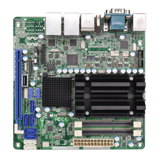
1.3 Motherboard Layout AD2550R/U3S8 17.0cm (6.7 in) RoHS AD2550R/U3S8 USB3_23 CPU_FAN2 CPU_FAN1 HDMI1 USB 2.0 T: USB2 B: USB3 USB 2.0 Super Top: T: USB4 RJ-45 B: USB5 USB 2.0 Top: T: USB6 RJ-45 16Mb B: USB7 BIOS AUX_PANEL1 CMOS... - Page 11 CPU Fan Connector (CPU_FAN1) CPU Fan Connector (CPU_FAN2) USB 3.0 Header (USB3_23, Black) CPU Heatsink 2 x 204-pin DDR3 SO-DIMM Slots (DDR3_A1, DDR3_A2, Black) ATX Power Connector (ATXPWR1) Chassis Fan Connector (CHA_FAN1) USB 2.0 Header (USB01, Blue) SATA2 Connector (SATA2_2, Blue) SATA3 Connector (SATA3_0, White) SATA3 Connector (SATA3_1, White) SATA2 Connector (SATA2_0, Blue)
- Page 12 AD2550RA/U3S3 17.0cm (6.7 in) RoHS AD2550RA/U3S3 USB3_23 CPU_FAN2 CPU_FAN1 HDMI1 USB 2.0 eSATA T: USB2 B: USB3 USB 2.0 Super Top: T: USB4 RJ-45 B: USB5 USB 2.0 Top: T: USB6 RJ-45 16Mb B: USB7 BIOS AUX_PANEL1 CMOS Battery USB01 HD_AUDIO1 TPMS1 SATA2_4...
- Page 13 CPU Fan Connector (CPU_FAN1) CPU Fan Connector (CPU_FAN2) USB 3.0 Header (USB3_23, Black) CPU Heatsink 2 x 204-pin DDR3 SO-DIMM Slots (DDR3_A1, DDR3_A2, Black) ATX Power Connector (ATXPWR1) Chassis Fan Connector (CHA_FAN1) USB 2.0 Header (USB01, Blue) SATA2 Connector (SATA2_2, Blue) SATA3 Connector (SATA3_0, White) SATA3 Connector (SATA3_1, White) SATA2 Connector (SATA2_0, Blue)
- Page 14 AD2550R/U3S3 17.0cm (6.7 in) RoHS AD2550R/U3S3 USB3_23 CPU_FAN2 CPU_FAN1 HDMI1 USB 2.0 eSATA T: USB2 B: USB3 USB 2.0 Super Top: T: USB4 RJ-45 B: USB5 USB 2.0 Top: T: USB6 RJ-45 16Mb B: USB7 BIOS AUX_PANEL1 CMOS Battery USB01 TPMS1 SATA2_4 SATA2_2...
- Page 15 CPU Fan Connector (CPU_FAN1) CPU Fan Connector (CPU_FAN2) USB 3.0 Header (USB3_23, Black) CPU Heatsink 2 x 204-pin DDR3 SO-DIMM Slots (DDR3_A1, DDR3_A2, Black) ATX Power Connector (ATXPWR1) Chassis Fan Connector (CHA_FAN1) USB 2.0 Header (USB01, Blue) SATA2 Connector (SATA2_2, Blue) SATA3 Connector (SATA3_0, White) SATA3 Connector (SATA3_1, White) SATA2 Connector (SATA2_0, Blue)
- Page 16 AD2550R 17.0cm (6.7 in) RoHS AD2550R CPU_FAN2 CPU_FAN1 HDMI1 USB 2.0 eSATA T: USB2 B: USB3 USB 2.0 Super Top: T: USB4 RJ-45 B: USB5 USB 2.0 Top: T: USB6 RJ-45 16Mb B: USB7 BIOS AUX_PANEL1 CMOS Battery TPMS1 SATA2_4 SATA2_2 USB10 USB89...
- Page 17 CPU Fan Connector (CPU_FAN1) CPU Fan Connector (CPU_FAN2) CPU Heatsink 2 x 204-pin DDR3 SO-DIMM Slots (DDR3_A1, DDR3_A2, Black) ATX Power Connector (ATXPWR1) Chassis Fan Connector (CHA_FAN1) SATA2 Connector (SATA2_2, Blue) SATA2 Connector (SATA2_0, Blue) SATA2 Connector (SATA2_1, Blue) SATA2 Connector (SATA2_3, Blue) SATA2 Connector (SATA2_4, Blue) USB 2.0 Header (USB89, Blue) System Panel Header (PANEL1, White)
-
Page 18: I/O Panel
1.4 I/O Panel AD2550RA/U3S3 1 PS/2 Keyboard / Mouse 10 Microphone (Pink) Port (Green) 11 Optical SPDIF Out Port 2 COM Port 12 USB 2.0 Ports (USB67) 3 USB 2.0 Ports (USB23) 13 USB 2.0 Ports (USB45) * 4 LAN RJ-45 Port 14 eSATA Port * 5 LAN RJ-45 Port 15 HDMI Port... - Page 19 AD2550R/U3S8 1 PS/2 Keyboard / Mouse 6 USB 2.0 Ports (USB67) Port (Green) 7 USB 2.0 Ports (USB45) 2 COM Port 8 HDMI Port 3 USB 2.0 Ports (USB23) 9 VGA Port * 4 LAN RJ-45 Port 10 USB 3.0 Ports (USB01) * 5 LAN RJ-45 Port * There are two LEDs on each LAN port.
- Page 20 AD2550R/U3S3 1 PS/2 Keyboard / Mouse 6 USB 2.0 Ports (USB67) Port (Green) 7 USB 2.0 Ports (USB45) 2 COM Port 8 eSATA Port 3 USB 2.0 Ports (USB23) 9 HDMI Port * 4 LAN RJ-45 Port 10 VGA Port * 5 LAN RJ-45 Port 11 USB 3.0 Ports (USB01) * There are two LEDs on each LAN port.
- Page 21 AD2550R 1 PS/2 Keyboard / Mouse 6 USB 2.0 Ports (USB67) Port (Green) 7 USB 2.0 Ports (USB54) 2 COM Port 8 eSATA Port 3 USB 2.0 Ports (USB01) 9 HDMI Port * 4 LAN RJ-45 Port 10 VGA Port * 5 LAN RJ-45 Port 11 USB 2.0 Ports (USB01) * There are two LEDs on each LAN port.
-
Page 22: Block Diagram
1.5 Block Diagram AD2550RA/U3S3 DDR3 x2 INTEL Atom 1066 MHz D2550 Processor VGA CONN HDMI CONN RSTOUT2# RSTOUT0# PCIE Slot Intel 82574L GLAN1 RSTOUT1# RSTOUT0# Etron EJ188 Intel USB 3.0 x4 82574L GLAN1 INTEL RSTOUT1# ICH10R Marvell 9172 SATAII x5 SATA3 x2 eSATA x1 AMI SPI 16M ROM... - Page 23 AD2550R/U3S8 DDR3 x2 VGA CONN INTEL Atom 1066 MHz D2550 Processor HDMI CONN RSTOUT2# RSTOUT0# PCIE Slot Realtek x1 or x4 RTL8111E GLAN1 RSTOUT1# RSTOUT0# Etron EJ188 Realtek USB 3.0 x4 RTL8111E GLAN2 INTEL RSTOUT1# Marvell 9120/9128 ICH10R SATAII x6...
- Page 24 AD2550R/U3S3 DDR3 x2 INTEL Atom 1066 MHz D2550 Processor VGA CONN HDMI CONN RSTOUT2# RSTOUT0# PCIE Slot Intel 82574L GLAN1 RSTOUT1# RSTOUT0# Etron EJ188 Intel USB 3.0 x4 82574L GLAN1 INTEL RSTOUT1# ICH10R Marvell 9172 SATAII x5 SATA3 x2 eSATA x1 AMI SPI 16M ROM High-Speed USB Rear x6 port...
- Page 25 AD2550R DDR3 x2 INTEL Atom 1066 MHz D2550 Processor VGA CONN HDMI CONN RSTOUT0# Intel 82574L GLAN1 RSTOUT0# Intel 82574L GLAN1 RSTOUT2# PCIE Slot INTEL ICH10R SATAII x5 eSATA x1 AMI SPI 16M ROM High-Speed USB Rear x6 port Front x4 port 1 port on MiniPCIE Super I/O 1 port on Type A...
-
Page 26: Installation
Chapter 2: Installation This is a Mini-ITX form factor (6.7" x 6.7", 17.0 x 17.0 cm) motherboard. Before you install the motherboard, study the configuration of your chassis to ensure that the motherboard fits into it. Make sure to unplug the power cord before installing or removing the motherboard. -
Page 27: Installation Of Memory Modules (So-Dimm)
2.3 Installation of Memory Modules (SO-DIMM) AD2550RA/U3S3 / AD2550R/U3S8 / AD2550R/U3S3 / AD2550R motherboard provides two 204-pin DDR3 (Double Data Rate 3) SO-DIMM slots. 1. It is not allowed to install a DDR or DDR2 memory module into DDR3 slot; otherwise, this motherboard and SO-DIMM may be damaged. -
Page 28: Expansion Slots (Pci Express Slots)
2.4 Expansion Slots (PCI Express Slots) There is 1 PCI Express slot on this motherboard. PCIE slots: AD2550RA/U3S3 / AD2550R/U3S8 / AD2550R/U3S3 PCIE1 (PCIE 1.0 x1 slot) is used for PCI Express x1 lane width cards. AD2550R PCIE1 (PCIE 1.0 x4 slot) is used for PCI Express x4 lane width cards. -
Page 29: Onboard Headers And Connectors
2.5 Onboard Headers and Connectors Onboard headers and connectors are NOT jumpers. Do NOT place jumper caps over these headers and connectors. Plac- ing jumper caps over the headers and connectors will cause permanent damage to the motherboard! Serial ATA2 Connectors These five Serial ATA2 (SATA2) connectors sup- (see p.12,14,16) - Page 30 USB 2.0 Headers Besides two default USB USB_PWR and Ports 2.0 ports on the I/O panel, DUMMY (9-pin USB0_1) there are are two USB 2.0 (see p.10,12,14) headers and one port on this motherboard. Each USB USB_PWR 2.0 header can support two USB_PWR (9-pin USB8_9) USB 2.0 ports.
- Page 31 PWRBTN (Power Switch): Connect to the power switch on the chassis front panel. You may configure the way to turn off your system using the power switch. RESET (Reset Switch): Connect to the reset switch on the chassis front panel. Press the reset switch to restart the computer if the computer freezes and fails to perform a normal restart.
- Page 32 B. Internet status indicator (2-pin LAN1_LED, LAN2_LED) These two 2-pin headers allow you to use the Gigabit internet indicator cable to connect to the LAN status indicator. When this indicator flickers, it means that the internet is properly connected. C. Chassis intrusion pin (4-pin CHASSIS) This header is provided for host computer chassis with chassis intrusion detection designs.
- Page 33 CPU Fan Connectors Please connect the CPU fan cable to the connector and (4-pin CPU_FAN1) GN D + 12V (see p.10,12,14,16) match the black wire to the CPU_ FAN_SPEED FAN_SPEED_CONTROL ground pin. Though this motherboard provides a 4-Pin CPU fan (Quiet Fan) connector, 3-Pin CPU fans can still work successfully even with- out the fan speed control function.
- Page 34 Chassis Fan Connector Please connect the fan cable FAN_VOLTAGE to the fan connector and (3-pin CHA_FAN1) CHA_FAN_SPEED match the black wire to the (see p.10,12,14,16) ground pin. IntA_P_D+ IntA_P_D- USB 3.0 Headers Besides eight default USB IntA_P_SSTX+ 3.0 ports on the I/O panel, (see p.10,12,14) IntA_P_SSTX- there are two USB 3.0...
-
Page 35: Driver Installation Guide
2.6 Driver Installation Guide To install the drivers to your system, please insert the support CD to your optical drive first. Then, the drivers compatible to your system can be auto- detected and listed on the support CD driver page. Please follow the order from top to bottom to install those required drivers. -
Page 36: Hot Plug For Hard Disk Drives
2.7 Hot Plug for Hard Disk Drives This motherboard supports Hot Plug for HDDs in AHCI / RAID mode. What is Hot Plug? If the HDDs are NOT set for RAID, it is called “Hot Plug” for the action to insert and remove the HDDs while the system is still powered on and in working condition. -
Page 37: Uefi Setup Utility
Chapter 3: UEFI SETUP UTILITY 3.1 Introduction This section explains how to use the UEFI SETUP UTILITY to configure your system. The UEFI chip on the motherboard stores the UEFI SETUP UTILITY. You may run the UEFI SETUP UTILITY when you start up the computer. -
Page 38: Navigation Keys
3.1.2 Navigation Keys Use < > key or < > key to choose among the selections on the menu bar, and use < > key or < > key to move the cursor up or down to select items, then press <Enter> to get into the sub screen. -
Page 39: Main Screen
3.2 Main Screen When you enter the UEFI SETUP UTILITY, the Main screen will appear and display the system overview. -
Page 40: Advanced Screen
3.3 Advanced Screen In this section, you may set the configurations for the following items: CPU Configuration, Chipset Configuration, Storage Configuration, Super IO Configuration, ACPI Configuration, USB Configuration, Voltage Control, ,Trusted Computing, and Serial Port Console Redirection. Setting wrong values in this section may cause the system to malfunction. -
Page 41: Cpu Configuration
3.3.1 CPU Configuration Intel Hyper Threading Technology To enable this feature, a computer system with an Intel processor that supports Hyper-Threading technology and an operating sys- tem that includes optimization for this technology is required. This option will be hidden if the installed CPU does not support Hyper- Threading technology. -
Page 42: Chipset Configuration
3.3.2 Chipset Configuration Spread Spectrum for Clockgen Select [Disabled] for better system stability. Restore on AC/Power Loss This allows you to set the power state after an unexpected AC/ power loss. If [Power Off] is selected, the AC/power remains off when the power recovers. -
Page 43: Storage Configuration
3.3.3 Storage Configuration Onboard SATAII Mode This item is for eSATA 5 and SATA2_0 to SATA2_4 ports. Use this to select SATA mode. Configuration options: [IDE Mode], [AHCI Mode], [RAID Mode] and [Disabled]. The default value is [AHCI Mode]. AHCI (Advanced Host Controller Interface) supports NCQ and other new features that will improve SATA disk performance but IDE mode does not have these advantages. - Page 44 ® We recommend to use Intel ICH10R SATA ports (SATA2_0 to SATA2_4) for your bootable devices. This will minimum your boot time and get the best performance. But if you still want to boot from the Marvell SATA3 controller, you can enable it from the UEFI.
-
Page 45: Super Io Configuration
3.3.4 Super IO Configuration COM1 Port Use this item to enable or disable the COM1 port. COM1 Port Address Use this to set the address for the onboard serial port. Configura- tion options: [3F8h / IRQ4] and [3E8h / IRQ4]. WDT Timeout Reset This allows you to enable or disable the Watchdog Timeout Reset function. -
Page 46: Acpi Configuration
3.3.5 ACPI Configuration Suspend to RAM Use this item to select whether to auto-detect or disable the Sus- pend-to-RAM feature. Selecting [Auto] will enable this feature if the OS supports it. Check Ready Bit Use this to enable or disable Check Ready Bit. ACPI HPET Table Use this item to enable or disable ACPI HPET Table. - Page 47 RTC Alarm Power On Use this item to enable or disable RTC (Real Time Clock) to pow- er on the system. USB Keyboard/Remote Power On Use this item to enable or disable USB Keyboard/Remote to turn on the system from the power-soft-off mode. USB Mouse Power On Use this item to enable or disable USB Mouse to turn on the sys- tem from the power-soft-off mode.
-
Page 48: Usb Configuration
3.3.6 USB Configuration USB 2.0 Controller Use this item to enable or disable the use of USB 2.0 controller. USB 3.0 Controller Use this item to enable or disable the use of USB 3.0 controller. Legacy USB Support Use this option to select legacy support for USB devices. There are four configuration options: [Enabled], [Auto], [Disabled] and [UEFI Setup Only]. -
Page 49: Voltage Control
3.3.7 Voltage Control DRAM Voltage Use this to select DRAM Voltage. The default value is [Auto]. +1.05V_CORE Voltage Use this to select +1.05V_CORE Voltage. The default value is [Auto]. +1.5V_ICH Voltage Use this to select +1.5V_ICH Voltage. The default value is [Auto]. +1.1V_ICH Voltage Use this to select +1.1V_ICH Voltage. -
Page 50: Trusted Computing
3.3.8 Trusted Computing TPM Support Use this option to enable or disable BIOS support for security devices. The default value is [Disabled]. -
Page 51: Serial Port Console Redirection
3.3.9 Serial Port Console Redirection Console Redirection Use this option to enable or disable Console Redirection. Console Redirection Settings Use this option to configure Console Redirection Settings. -
Page 52: Hardware Health Event Monitoring Screen
3.4 Hardware Health Event Monitoring Screen In this section, it allows you to monitor the status of the hardware on your system, including the parameters of the CPU temperature, motherboard temperature and the critical voltage. CPU Fan 1 Setting This allows you to set the speed of CPU fan 1. The default value is [Full On]. -
Page 53: Boot Screen
3.5 Boot Screen In this section, it will display the available devices on your system for you to configure the boot settings and the boot priority. Boot Option #1 Select boot option #1. Boot Option #2 Select boot option #2. USB Device BBS Priorities Set the boot priorities for USB devices. - Page 54 Boot From Onboard LAN Use this item to enable or disable the Boot From Onboard LAN feature.
-
Page 55: Security Screen
3.6 Security Screen In this section, you may set or change the supervisor/user password for the system. For the user password, you may also clear it. Secure Boot Use this to enable or disable Secure Boot Control. The default value is [Disabled]. -
Page 56: Exit Screen
3.7 Exit Screen Save Changes and Exit When you select this option, the following message “Save con- figuration changes and exit setup?” will pop-out. Select [Yes] to save the changes and exit the UEFI SETUP UTILITY. Discard Changes and Exit When you select this option, the following message “Discard changes and exit setup?”... -
Page 57: Software Support
4.2.4 Contact Information If you need to contact ASRock Rack or want to know more about AS- Rock Rack, you’re welcome to visit ASRock Rack’s website at http:// www.ASRockRack.com; or you may contact your dealer for further... -
Page 58: Troubleshooting
Chapter 5: Troubleshooting 5.1 Troubleshooting Procedures Follow the procedures below to troubleshoot your system. Always unplug the power cord before adding, removing or changing any hardware components. Failure to do so may cause physical injuries to you and damages to motherboard components. 1. - Page 59 2. Confirm whether your power supply provides adaquate and stable power. Other problems... 1. Try searching keywords related to your problem on ASRock Rack’s page: http://www.ASRockRack.com/support/faq.asp 2. Try downloading and updating the latest UEFI on ASRock Rack’s website: http://www.ASRockRack.com/support/download.asp...
-
Page 60: Technical Support Procedures
5.2 Technical Support Procedures If you have tried the troubleshooting procedures mentioned above and the problems are still unsolved, please contact ASRock Rack’s technical support with the following information: 1. Your contact information 2. Model name, BIOS version and problem type.
Need help?
Do you have a question about the AD2550R/U3S8 and is the answer not in the manual?
Questions and answers