Sign In
Upload
Download
Table of Contents
Contents
Add to my manuals
Delete from my manuals
Share
URL of this page:
HTML Link:
Bookmark this page
Add
Manual will be automatically added to "My Manuals"
Print this page
×
Bookmark added
×
Added to my manuals
Manuals
Brands
ASROCK Rack Manuals
Motherboard
B650D4U-1L
User manual
ASROCK Rack B650D4U-1L User Manual
Hide thumbs
1
2
3
Table Of Contents
4
5
6
7
8
9
10
11
12
13
14
15
16
17
18
19
20
21
22
23
24
25
26
27
28
29
30
31
32
33
34
35
36
37
38
39
40
41
42
43
44
45
46
47
48
49
50
51
52
53
54
55
56
57
58
59
60
61
62
63
64
65
66
67
68
69
70
71
72
73
74
page
of
74
Go
/
74
Contents
Table of Contents
Bookmarks
Table of Contents
Table of Contents
Chapter 1 Introduction
Package Contents
Specifications
Unique Features
Motherboard Layout
Onboard LED Indicators
I/O Panel
Block Diagram
Chapter 2 Installation
Screw Holes
Pre-Installation Precautions
Installing the CPU
Installing the CPU Fan and Heatsink
Installing Memory Modules (DIMM)
Expansion Slots (PCI Express Slots)
Onboard Headers and Connectors
Dr. Debug
SSD Module Installation Guide
Chapter 3 UEFI Setup Utility
Introduction
UEFI Menu Bar
Navigation Keys
Main Screen
Advanced Screen
CPU Configuration
Chipset Configuration
Nvme Configuration
ACPI Configuration
USB Configuration
PCI Subsystem Settings
Amd Cbs
Hardware Monitor
Network Stack Configuration
Driver Health
Tls Auth Configuration
Amd Pbs
Inter (R) I210 Gigabit Network Connection
VLAN Configuration
Ipv4 Network Configuration
Ipv6 Network Configuration
Security
Install Default Secure Boot Keys
Key Management
Boot Screen
Exit Screen
Chapter 4 Software Support
Download and Install Operating System
Advertisement
Quick Links
1
Specifications
2
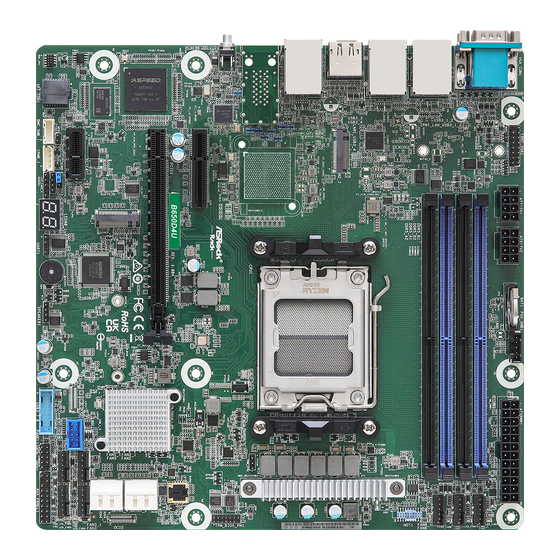
Motherboard Layout
3
Download and Install Operating System
Download this manual
B650D4U-1L
B665D4U-1L
User Manual
Version 1.0
Published November 2022
Copyright©2022 ASRock Rack INC. All rights reserved.
Table of
Contents
Previous
Page
Next
Page
1
2
3
4
5
Advertisement
Table of Contents
Need help?
Do you have a question about the B650D4U-1L and is the answer not in the manual?
Ask a question
Questions and answers
Related Manuals for ASROCK Rack B650D4U-1L
Motherboard ASROCK Rack B665D4U-1L User Manual
(74 pages)
Motherboard ASROCK Rack 2U1G-B650/EVAC User Manual
(35 pages)
Motherboard ASROCK Rack B650D4U3 User Manual
(95 pages)
Motherboard ASROCK Rack B650D4U3-2L2Q/BCM Quick Installation Manual
(2 pages)
Motherboard ASROCK Rack BERGAMOD8-2L2T User Manual
Server/workstation motherboards (100 pages)
Motherboard ASROCK Rack ALTRAD8UD-1L User Manual
(84 pages)
Motherboard ASROCK Rack C236 WSI User Manual
Mini itx motherboard (69 pages)
Motherboard ASRock Rack EP2C612D16NM User Manual
Ep2c612d16nm series (99 pages)
Motherboard ASROCK Rack E3C236D4I-44E85 User Manual
(79 pages)
Motherboard ASROCK Rack EP2C622D16NM User Manual
Server / workstation (87 pages)
Motherboard ASROCK Rack EP2C621D12 WS User Manual
Stable and reliable solution, server/workstation motherboard (99 pages)
Motherboard ASROCK Rack EPC621D4I-2M User Manual
(81 pages)
Motherboard ASROCK Rack E3C246D2I User Manual
(83 pages)
Motherboard ASROCK Rack ROMED8-2T User Manual
Server/workstation (86 pages)
Motherboard ASROCK Rack X570D4U-2L2T User Manual
Server/workstation (88 pages)
Motherboard ASROCK Rack ROME2D16-2T User Manual
Server/workstation motherboard (98 pages)
This manual is also suitable for:
B665d4u-1l
Table of Contents
Print
Rename the bookmark
Delete bookmark?
Delete from my manuals?
Login
Sign In
OR
Sign in with Facebook
Sign in with Google
Upload manual
Upload from disk
Upload from URL


Need help?
Do you have a question about the B650D4U-1L and is the answer not in the manual?
Questions and answers