
Related Manuals for ASROCK Rack ALTRAD8UD-1L


Summary of Contents for ASROCK Rack ALTRAD8UD-1L
- Page 1 ALTRAD8UD-1L2T User Manual Version 1.0 Published July 2023 Copyright©2023 ASRock Rack INC. All rights reserved.
- Page 2 In no event shall ASRock Rack, its directors, officers, employees, or agents be liable for any indirect, special, incidental, or consequential damages (including damages for loss of...
- Page 3 ASRock Rack follows the green design concept to design and manufacture our products, and makes sure that each stage of the product life cycle of ASRock Rack product is in line with global environmental regulations. In addition, ASRock Rack disclose the relevant in- formation based on regulation requirements.
-
Page 4: Table Of Contents
Contents Chapter 1 Introduction Package Contents Specifications Unique Features Motherboard Layout Onboard LED Indicators I/O Panel Block Diagram Chapter 2 Installation Screw Holes Pre-installation Precautions Installing the CPU Installation of Memory Modules (DIMM) Expansion Slots (PCI Express Slots) Onboard Headers and Connectors ATX PSU / DC-IN Power Connections Unit Identification purpose LED/Switch Dual LAN and Teaming Operation Guide... - Page 5 Main Screen 3.2.1 Mother Board Information 3.2.2 Processor Information 3.2.3 Memory Information Advanced Screen 3.3.1 CPU Configuration 3.3.2 RAS Configuration 3.3.3 Chipset Configuration 3.3.4 NVMe Configuration 3.3.5 ACPI Configuration 3.3.6 USB Configuration 3.3.7 Serial Port Console Redirection 3.3.8 H/W Monitor 3.3.9 Network Stack Configuration 3.3.10 Driver Health 3.3.11 Tls Auth Configuration...
- Page 6 Exit Screen Chapter 4 Software Support Download and Install Operating System Download and Install Software Drivers Contact Information Chapter 5 Troubleshooting Troubleshooting Procedures Technical Support Procedures Returning Merchandise for Service...
-
Page 7: Chapter 1 Introduction
In case any modifications of this manual occur, the updated version will be available on ASRock Rack website without further notice. Find the latest memory and CPU support lists on ASRock Rack website as well. ASRock Rack’s Website: www.ASRockRack.com Please visit the website for more specific information about the using model. -
Page 8: Specifications
1.2 Specifications ALTRAD8UD-1L / ALTRAD8UD-1L2T Physical Status Form Factor Deep Micro-ATX Dimension 9.6” x 10.5” (24.4cm x 26.7cm) Processor System Supports Ampere® Altra® Max/Ampere® Altra® Processor Socket 1 Socket (LGA-4926) Chipset System on Chip System Memory Supported DIMM 8 DIMM slots (1DPC) - Page 9 System BIOS Type AMI UEFI BIOS; 256 Mb (32MB) SPI Flash ROM Features ASRock Rack Instant Flash, ACPI 6.2, SMBIOS 3.4.0 and above, Plug and Play(PnP) Internal Connectors/Headers PSU Connector 1 (4-pin, ATX PSU signal) w/ ATX 24-pin adapter cable, 3 (8-...
- Page 10 IPMB Header Clear CMOS 1 (contact pads) USB3.2 (Gen1) 1 (19-pin, 2 USB3.2 Gen1) Header LED Indicators Standby Power 1 (5VSB) Fan Fail LED BMC Heartbeat Supported OS - RHEL 8.5 aarch64 - RHEL 9.2 aarch64 - CentOS-Stream 8 aarch64 - CentOS-Stream 9 aarch64 Please refer to the website for the latest OS support list.
-
Page 11: Unique Features
With this utility, press the <F6> key during the POST or the <F2> key to enter into the BIOS setup menu to access ASRock Rack Instant Flash. Just launch this tool and save the new BIOS file to the USB flash drive, floppy disk or hard drive, then update the BIOS only in a few clicks without preparing an additional floppy diskette or other complicated flash utility. -
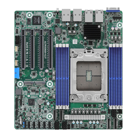
Page 12: Motherboard Layout
T:USB3_2 B:USB3_1 USB 3.2 ATX12V2 DDR4_E1 Gen1 Ports IPMI T:USB3_4 DDR4_F1 B:USB3_3 DDR4_G1 BIOS ATX12V3 SLIMLINE3 UID1 DDR4_H1 PCIE7 FAN1 SLIMLINE4 ALTRAD8UD-1L FAN2 ALTRAD8UD-1L2T PCIE6 FAN3 ASPEED AST2500 FAN4 PCIE5 FAN5 PCIE4 BAT1 TPM_BIOS_PH1 CLRMOS1 USB3_3_1 HSBP1 BMC_SMB_1 IPMB1 AUX_PANEL1... - Page 13 ALTRAD8UD-1L ALTRAD8UD-1L2T Description Front VGA Header (FRNT_VGA1) OCuLink Connector (PCIe4.0 x4) (OCU1) OCuLink Connector (PCIe4.0 x4) (OCU2) 2 x 288-pin DDR4 DIMM Slots (DDR4_A1, DDR4_C1)* 2 x 288-pin DDR4 DIMM Slots (DDR4_B1, DDR4_D1)* Micro-Fit ATX 4Pin Power Connector (ATX4PIN1) ATX 12V Power Connector (ATX12V1)
- Page 14 Description Front LAN LED Connector (LED_LAN3) PCI Express 4.0 x16 Slot (PCIE4) PCI Express 4.0 x16 Slot (PCIE5) PCI Express 4.0 x16 Slot (PCIE6) PCI Express 4.0 x16 Slot (PCIE7) 2 x 288-pin DDR4 DIMM Slots (DDR4_F1, DDR4_H1)* 2 x 288-pin DDR4 DIMM Slots (DDR4_E1, DDR4_G1)* *For DIMM installation and configuration instructions, please see p.19 (Installation of Memory Modules (DIMM)) for more details.
-
Page 15: Onboard Led Indicators
ALTRAD8UD-1L ALTRAD8UD-1L2T 1.5 Onboard LED Indicators The layout below is only for ALTRAD8UD-1L2T reference, both 1L2T and 1L LED locations are the same. - Page 16 Item Status Description LED_FAN1 FAN1 Fail LED_FAN2 FAN2 Fail LED_FAN3 FAN3 Fail LED_FAN4 FAN4 Fail LED_FAN5 FAN5 Fail Green CPLD Ready OVERTEMP CPU Fail Alert HIGHTEMP CPU SB_PWR1 Green STB PWR Ready LED6/LED5/LED4/LED3 0 : 0 : 0 : 0 Waiting for BMC Ready and Power Event.
-
Page 17: I/O Panel
ALTRAD8UD-1L ALTRAD8UD-1L2T 1.6 I/O Panel No. Description No. Description VGA Port (VGA1) 1G LAN RJ-45 Port (LAN3)** 10G LAN RJ-45 Port (LAN2)*** USB 3.2 Gen1 Ports (USB3_3_4) (ALTRAD8UD-1L2T only) 10G LAN RJ-45 Port LAN RJ-45 Port (IPMI)* (LAN1, shared NIC)*** (ALTRAD8UD-1L2T only) USB 3.2 Gen1 Ports (USB3_1_2) - Page 18 **There is an LED on each side of 1G LAN port. Please refer to the table below for the LAN port LED indications. ACT/LINK LED SPEED LED LAN Port 1G LAN Port LED Indications Activity / Link LED Speed LED Status Description Status...
-
Page 19: Block Diagram
ALTRAD8UD-1L ALTRAD8UD-1L2T 1.7 Block Diagram ALTRAD8UD-1L2T Block Diagram 4×PCIe x16 Slot RCA2 PCIE SLOT4 DDR4 1DIMM/Channel DDR4 DDR4 DDR 0, 1, 2, 3 RCA3 PCIE SLOT6 DDR4 DDR4 RCA6 PCIE SLOT7 DDR4 RCA7 PCIE SLOT6 DDR4 DDR 4, 5, 6, 7... -
Page 20: Chapter 2 Installation
Chapter 2 Installation This is a deep micro-ATX form factor (9.6” x 10.5”) motherboard. Before installing the motherboard, study the configuration of the chassis to ensure that the motherboard fits into it. Make sure to unplug the power cord before installing or removing the motherboard. Failure to do so may cause physical injuries and motherboard damages. -
Page 21: Installing The Cpu
ALTRAD8UD-1L ALTRAD8UD-1L2T 2.3 Installing the CPU LOTES SKT4926 5->4->3->2->1... - Page 22 Remove Socket Cap Insert CPU...
- Page 23 ALTRAD8UD-1L ALTRAD8UD-1L2T 1->2->3->4->5...
- Page 25 ALTRAD8UD-1L ALTRAD8UD-1L2T FOXCONN SKT4926 4->3->2->1...
- Page 26 Remove Socket Cap Insert CPU...
- Page 27 ALTRAD8UD-1L ALTRAD8UD-1L2T 1->2->3->4...
-
Page 29: Installation Of Memory Modules (Dimm)
ALTRAD8UD-1L ALTRAD8UD-1L2T 2.4 Installation of Memory Modules (DIMM) This motherboard provides eight 288-pin DDR4 (Double Data Rate 4) DIMM slots in two groups, and supports Single Channel Memory Technology. CPU1 DDR4_A1, B1, C1, D1 DDR4_E1, F1, G1 H1 1. For Eight channel configuration, it always needs to install identical (the same brand, speed, size and chip-type) DDR4 DIMM groups. -
Page 31: Expansion Slots (Pci Express Slots)
ALTRAD8UD-1L ALTRAD8UD-1L2T 2.5 Expansion Slots (PCI Express Slots) There are 4 PCI Express slots on this motherboard. PCIE slots: PCIE4 (PCIE 4.0 x16 slot, from CPU1) is used for PCI Express x16 lane width cards. PCIE5 (PCIE 4.0 x16 slot, from CPU1) is used for PCI Express x16 lane width cards. -
Page 32: Onboard Headers And Connectors
2.6 Onboard Headers and Connectors Onboard headers and connectors are NOT jumpers. Do NOT place jumper caps over these headers and connectors. Placing jumper caps over the headers and connectors will cause permanent damage to the motherboard. System Panel Header Connect the power switch, PLED+ PLED-... - Page 33 ALTRAD8UD-1L ALTRAD8UD-1L2T Auxiliary Panel Header This header supports multiple (18-pin AUX_PANEL1) functions on the front panel, (see p.6, No. 25) including the front panel SMB, internet status indicator and chassis intrusion pin. A. Front panel SMBus connecting pin (6-1 pin FPSMB) This header allows user to connect SMBus (System Management Bus) equipment.
- Page 34 Thermal Sensor Header Please connect the thermal (3-pin TR1) sensor cable to this header (see p.6, No. 32) and the other end to the device which can monitor its temperature. PWM Configuration The header is used for PWM Header configurations. (3-pin PWM_CFG1) (see p.6, No.
- Page 35 ALTRAD8UD-1L ALTRAD8UD-1L2T Backplane PCI Express This connector is used for the Hot-Plug Connector hot plug feature of HDDs on CPU_HP_SCL CPU_HP_SDA (5-pin HSBP1) the backplane. P0_HP_ALERT_L (see p.6, No. 29) Clear CMOS Pad This allows user to clear (CLRMOS1) the data in CMOS. To clear (see p.6, No.
- Page 36 PSU SMBus Header PSU SMBus monitors the ALERT SMBCLK (5-pin PSU_SMB1) status of the power supply, fan (see p.6, No. 8) and system temperature. SMBDATA ATX 12V Power This motherboard provides Connectors three 8-pin ATX 12V power (8-pin ATX12V1) connectors. (see p.6, No.
- Page 37 ALTRAD8UD-1L ALTRAD8UD-1L2T Intelligent Platform This 4-pin connector is IPMB_SDA IPMB_SCL Management Bus Header used to provide a cabled (4-pin IPMB1) base-board or front panel No connect (see p.6, No. 33) connection for value added features and 3rd-party add- in cards, such as Emergency...
- Page 38 Slimline NVMe These connectors are used for B Side (Latch) Connectors the NVME PCIE devices. (SLIMLINE1) (see p.6, No. 9) (SLIMLINE2) (see p.6, No. 10) (SLIMLINE3) (see p.6, No. 14) (SLIMLINE4) (see p.6, No. 16) 77 79 78 80...
- Page 39 ALTRAD8UD-1L ALTRAD8UD-1L2T 80-pin Defeinition Pin Defeinition GND_1 GDN12 RX0_DP TX0_DP RX0_DN TX0_DN GDN2 GDN13 RX1_DP TX1_DP RX1_DN TX1_DN GDN3 GDN14 SIDEBAND1 SMBCLK WAKE SMBDAT 100M Clock DP PERST# 100M Clock DN PRSNT# GDN4 GDN15 RX2_DP TX2_DP RX2_DN TX2_DN GDN5 GDN16...
-
Page 40: Atx Psu / Dc-In Power Connections
2.7 ATX PSU / DC-IN Power Connections This motherboard supports both +12V DC and ATX power input. Please refer to the table below for the required connections between the motherboard and the power supply. Connector DC-IN ATX PSU 12V 8pin ATX 4pin (with the bundled ATX 24pin-to-4pin converter cable) -
Page 41: Unit Identification Purpose Led/Switch
ALTRAD8UD-1L ALTRAD8UD-1L2T 2.8 Unit Identification purpose LED/Switch With the UID button, user can locate the server working on from behind a rack of servers. Unit Identification When the UID button on the purpose LED/Switch front or rear panel is pressed,... -
Page 42: Dual Lan And Teaming Operation Guide
2.9 Dual LAN and Teaming Operation Guide Dual LAN with Teaming enabled on the motherboard allows two single connections to act as one single connection for twice the transmission bandwidth, making data transmission more effective and improving the quality of transmission of distant images. Fault tolerance on the dual LAN network prevents network downtime by transferring the workload from a failed port to a working port. -
Page 43: Ssd Module Installation Guide
ALTRAD8UD-1L ALTRAD8UD-1L2T 2.10 M.2 SSD Module Installation Guide The M.2 Socket (M2_1/M2_2, Key M) supports type 2230/2280 SATA3 6.0 Gb/s module or a M.2 PCI Express module up to Gen4 x4 (16GT/s x4). Installing the M.2 SSD Module Step 1 Prepare a M.2 SSD module and the... - Page 44 Step 3 Move the standoff based on the module type and length. Skip Step 3 and 4 and go straight to NUT80 NUT30 Step 5 when using the default nut. Otherwise, release the standoff by hand. Step 4 Peel off the protective film on the nut to be used.
-
Page 45: Chapter 3 Uefi Setup Utility
ALTRAD8UD-1L ALTRAD8UD-1L2T Chapter 3 UEFI Setup Utility 3.1 Introduction This section explains how to use the UEFI SETUP UTILITY to configure the system. The UEFI chip on the motherboard stores the UEFI SETUP UTILITY. Run the UEFI SETUP UTILITY when starting up the computer. Please press <F2> or <Del> during the Power- On-Self-Test (POST) to enter the UEFI SETUP UTILITY;... -
Page 46: Navigation Keys
3.1.2 Navigation Keys Please check the following table for the function description of each navigation key. Navigation Key(s) Function Description Moves cursor left or right to select Screens Moves cursor up or down to select items + / - To change option for the selected items <Tab>... -
Page 47: Main Screen
ALTRAD8UD-1L ALTRAD8UD-1L2T 3.2 Main Screen Once entering the UEFI SETUP UTILITY, the Main screen will appear and display the system overview. The Main screen provides system overview information and allows user to set the system time and date. -
Page 48: Mother Board Information
3.2.1 Mother Board Information Press <Enter> to view the information of the motheboard. 3.2.2 Processor Information Press <Enter> to view the information of the processor. -
Page 49: Memory Information
ALTRAD8UD-1L ALTRAD8UD-1L2T 3.2.3 Memory Information Press <Enter> to view the information of the memory. -
Page 50: Advanced Screen
3.3 Advanced Screen In this section, set the configurations for the following items: CPU Configuration, RAS Configuration, Chipset Configuration, NVME Configuration, ACPI Configuration, USB Configuration, Serial Port Console Redirection, H/W Monitor, Network Stack Configura- tion, Driver Health, Tls Auth Configuration and Instant Flash. Setting wrong values in this section may cause the system to malfunction. -
Page 51: Cpu Configuration
ALTRAD8UD-1L ALTRAD8UD-1L2T 3.3.1 CPU Configuration Enable number of cores Use this item to enable the number of cores for the sysem. ARM ERRATA 1542419 workaround This item includes Disable, Workaround and Disable options used for trapping each IC IVAU to EL3. - Page 52 SLC as L3$ Use this item to enable or disable PPTT to indicate SLC as L3$. This is limited to only 1P Monolithic mode.
-
Page 53: Ras Configuration
ALTRAD8UD-1L ALTRAD8UD-1L2T 3.3.2 RAS Configuration Hardware EINJ Use this item to enable or disable hardware EINJ support. If disabled, the EINJ is software simulated. DRAM EINJ No Trigger Avoid triggering DRAM errors with Hardware EINJ. If enabled, DRAM Hardware EINJ requests will only flip bits at the desired DRAM address and not force the hardware to immediately detect those bit flips. - Page 54 Processor OS-first Use this item to enable the operating system to prioritize processor errors through the AEST ACPU table. DDR CE Threshold This specifies the Number of DDR CEs to occur before using interrupt based notification to the OS rather than allowing the OS to poll for CEs. Processor CE Threshold This specifies the Number of processor CEs to occur before using interrupt based notification to the OS rather than allowing the OS to poll for CEs.
-
Page 55: Chipset Configuration
ALTRAD8UD-1L ALTRAD8UD-1L2T 3.3.3 Chipset Configuration SR-IOV Support If system has SR-IOV capable PCIe Devices, this option Enables or Disables Single Root IO Virtualization Support. APEI Enable Use this item to enable or disable ACPI Platform Error Interface support. PCIE Link Width Select this item to configue PCIE Link Width. - Page 56 PCIE Link Speed Select this item to configure PCIE Link Speed. SLIM1-1 Link Speed Use this item to select SLIM1-1 Link Speed. The default value is [Auto]. SLIM1-2 Link Speed Use this item to select SLIM1-2 Link Speed. The default value is [Auto]. SLIM2-1 Link Speed Use this item to select SLIM2-1 Link Speed.
-
Page 57: Nvme Configuration
ALTRAD8UD-1L ALTRAD8UD-1L2T 3.3.4 NVMe Configuration NVMe Configuration The NVMe Configuration displays the NVMe controller and Drive information. -
Page 58: Acpi Configuration
3.3.5 ACPI Configuration RTC Alarm Power On Configuration Use this item to set RTC Alarm Power On Time. RTC Alarm Power On Use this item to enable or disable RTC (Real Time Clock) to power on the system. RTC Alarm Date Use this item to set Date of RTC power on feature. -
Page 59: Usb Configuration
ALTRAD8UD-1L ALTRAD8UD-1L2T 3.3.6 USB Configuration USB Configuration The USB Configuration displays the USB Module Version, USB Controllers and USB Device informations. -
Page 60: Serial Port Console Redirection
3.3.7 Serial Port Console Redirection COM0 Console Redirection Use this option to enable or disable Console Redirection. If this item is set to Enabled, user can select a COM Port to be used for Console Redirection. Console Redirection Settings Use this option to configure Console Redirection Settings, and specify how the computer and the host computer to which are connected exchange information. - Page 61 ALTRAD8UD-1L ALTRAD8UD-1L2T Bits Per Second Use this item to select the serial port transmission speed. The speed used in the host computer and the client computer must be the same. Long or noisy lines may require lower transmission speed. The options include [9600], [19200], [38400], [57600] and [115200].
- Page 62 Out-of-Band Mgmt Port Microsof t Windows Emergency Management Services (EMS) allows for remote management of a Windows Server OS through a serial port. Terminal Type EMS Use this item to select the preferred terminal emulation type for out-of-band management. It is recommended to select [VT-UTF8]. Option Description VT100...
-
Page 63: H/W Monitor
ALTRAD8UD-1L ALTRAD8UD-1L2T 3.3.8 H/W Monitor In this section, it allows user to monitor the status of the hardware on the system, includ- ing the parameters of the CPU temperature, motherboard temperature, CPU fan speed, chassis fan speed, and the critical voltage. -
Page 64: Network Stack Configuration
3.3.9 Network Stack Configuration Network Stack Enable UEFI network stack can prevents user from performing single-user network boots and network installation. If disabled, the host does not use the network interface. IPv4 PXE Support Enable IPv4 PXE Boot support. If disabled, IPv4 PXE Boot Option is not supported. IPv4 HTTP Support Enable IPv4 HTTP Boot support. -
Page 65: Driver Health
ALTRAD8UD-1L ALTRAD8UD-1L2T 3.3.10 Driver Health Interl (R) PRO/1000 Open Source 9.2.06 PCI-E Healthy This provides Health Status for the drivers and controllers. Interl (R) 10GbE Open Source 8.2.06 AArch64 Healthy This provides Health Status for the drivers and controllers. -
Page 66: Tls Auth Configuration
3.3.11 Tls Auth Configuration Server CA Configuration Press <Enter> to configure Server CA. Client Cert Configuration Enroll Cert Press <Enter> to enroll cert. Delete Cert Press <Enter> to delete cert. -
Page 67: Instant Flash
ALTRAD8UD-1L ALTRAD8UD-1L2T 3.3.12 Instant Flash Instant Flash is a UEFI flash utility embedded in Flash ROM. This convenient UEFI update tool allows you to update system UEFI without entering operating systems. Just save the new UEFI file to the USB flash drive, floppy disk or hard drive and launch this tool, then updating the UEFI only in a few clicks without preparing an additional floppy diskette or other complicated flash utility. -
Page 68: Server Mgmt
3.4 Server Mgmt Wait For BMC Wait For BMC response for specified time out. BMC starts at the same time when BIOS starts during AC power ON. It takes around 90 seconds to initialize Host to BMC interfaces. FRB-2 Timer Use this item to enable or disable FRB-2 timer (POST timer) FRB-2 Timer Timeout Use this item to define the FRB-2 Time Expiration between 1 to 30 value. - Page 69 ALTRAD8UD-1L ALTRAD8UD-1L2T OS Wtd Timer Policy Configure how the system should respond if the OS Boot Watchdog Timer expires. If the OS Boot Watchdog Timer is disabled, this item is not available. Power Control Policy Configure how the system should respond if AC Power is lost. Reset is not required when the selected Power policy is set and saved in BMC.
-
Page 70: Bmc Network Configuration
3.4.1 BMC Network Configuration Lan Channel (Failover) Manual Setting IPMI LAN If [No] is selected, the IP address is assigned by DHCP. If you prefer using a static IP address, toggle to [Yes], and the changes take effect after the system reboots. The default value is [No]. - Page 71 ALTRAD8UD-1L ALTRAD8UD-1L2T When [DHCP] or [Static] is selected, do NOT modify the BMC network settings on the IPMI web page. The default login information for the IPMI web interface is: Username: admin Password: admin For more instructions on how to set up remote control environment and use the IPMI man- agement platform, please refer to the IPMI Configuration User Guide or go to the Support website at: http://www.asrockrack.com/support/ipmi.asp...
-
Page 72: System Event Log
3.4.2 System Event Log SEL Components Change this item to enable ro disable event logging for error/progress codes during boot. Erase SEL Use this item to choose options for earsing SEL. When SEL is Full Use this to choose options for reactions to a full SEL. Log EFI Status Codes Use this item to disable the logging of EFI Status Codes or log only error code or only progress code or both. -
Page 73: Bmc Tools
ALTRAD8UD-1L ALTRAD8UD-1L2T 3.4.3 BMC Tools Load BMC Default Settings Use this item to load BMC default settings. -
Page 74: Security
3.5 Security This section allows user to set or change the supervisor/user password for the system. For the user password also can clear it. Supervisor Password Set or change the password for the administrator account. Only the administrator has authority to change the settings in the UEFI Setup Utility. Leave it blank and press enter to remove the password. - Page 75 ALTRAD8UD-1L ALTRAD8UD-1L2T Install Default Secure Boot Keys Please install default secure boot keys if it’s the first time useing secure boot. Clear Secure Boot Keys Use this to clear the secure boot keys.
-
Page 76: Key Management
3.5.1 Key Management In this section, expert users can modify Secure Boot Policy variables without full authenti- cation. -
Page 77: Boot
ALTRAD8UD-1L ALTRAD8UD-1L2T 3.6 Boot In this section, it will display the available devices on your system for you to configure the boot settings and the boot priority. Boot Option #1 Use this item to set the system boot order. Boot Option #2 Use this item to set the system boot order. - Page 78 UEFI USB Drive BBS Priorities Specifies the Boot Device Priority sequence from available UEFI USB Drives. UEFI Application Boot Priorities Specifies the Boot Device Priority sequence from available UEFI Application. Setup Prompt Timeout Configure the number of seconds to wait for the UEFI setup utility. Bootup NumLock State If this item is set to [On], it will automatically activate the Numeric Lock function after boot-up.
-
Page 79: Exit Screen
ALTRAD8UD-1L ALTRAD8UD-1L2T 3.7 Exit Screen Save Changes and Exit When selecting this item, the following message “Save configuration changes and exit setup?” will pop-out. Press <F10> key or select [Yes] to save the changes and exit the UEFI SETUP UTILITY. -
Page 80: Chapter 4 Software Support
4.3 Contact Information If you need to contact ASRock Rack or want to know more about ASRock Rack, welcome to visit ASRock Rack’s website at http://www.ASRockRack.com; or you may contact your dealer... -
Page 81: Chapter 5 Troubleshooting
ALTRAD8UD-1L ALTRAD8UD-1L2T Chapter 5 Troubleshooting 5.1 Troubleshooting Procedures Follow the procedures below to troubleshoot the system. Always unplug the power cord before adding, removing or changing any hardware com- ponents. Failure to do so may cause physical injuries to you and damages to motherboard components. - Page 82 1. Verify if the battery on the motherboard provides ~3VDC. Install a new battery if it does not. 2. Confirm whether your power supply provides adaquate and stable power. Other problems... 1. Try searching keywords related to your problem on ASRock Rack’s FAQ page: http://www.asrockrack.com/support...
-
Page 83: Technical Support Procedures
ALTRAD8UD-1L ALTRAD8UD-1L2T 5.2 Technical Support Procedures If the problems are still unsolved, please contact ASRock Rack’s technical support with the following information: 1. Contact information 2. Model name, BIOS version and problem type. 3. System configuration. 4. Problem description. Contact ASRock Rack’s technical support at: http://www.asrockrack.com/support/tsd.asp... - Page 84 Contact Information If it needs to contact ASRock Rack or want to know more about ASRock Rack, you’re welcome to visit ASRock Rack’s website at http://www.asrockrack.com; or contact the dealer for further information. For technical questions, please submit a support request form at https://event.asrockrack.com/tsd.asp...
Need help?
Do you have a question about the ALTRAD8UD-1L and is the answer not in the manual?
Questions and answers