
Related Manuals for Motorola RFS4011 Series


Summary of Contents for Motorola RFS4011 Series
- Page 1 RFS4000_Baseline.book Page 1 Tuesday, September 28, 2010 9:55 AM RFS4011 Series Integrated Services Controller Installation Guide...
- Page 2 RFS4000_Baseline.book Page 2 Tuesday, September 28, 2010 9:55 AM MOTOROLA and the Stylized M Logo are registered in the US Patent & Trademark Office. Symbol is a registered trademark of Symbol Technologies, Inc. All other product or service names are the property of their respective owners. © Motorola, Inc. 2010. All rights reserved.
-
Page 3: Table Of Contents
RFS4000_Baseline.book Page 3 Tuesday, September 28, 2010 9:55 AM Contents 1.0 Introduction ......... 1 2.0 Specifications . - Page 4 RFS4000_Baseline.book Page 4 Tuesday, September 28, 2010 9:55 AM...
-
Page 5: Introduction
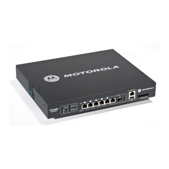
RFS4000_Baseline.book Page 1 Tuesday, September 28, 2010 9:55 AM Introduction Introduction The Motorola RFS4011 Series Integrated Services Controller is a member of Motorola’s RFS Series Integrated Services Controller family. The RFS4011 provides centralized Wireless LAN (WLAN) configuration and management by coalescing a network “intelligence” previously spread across physically distributed access points. - Page 6 Verify the electrical circuits have appropriate overload protection. • Motorola strongly recommends the use of an Uninterruptible Power Supply (UPS) that supports the RFS4011 Series • Integrated Services Controller power rating. Not using a UPS can result in data loss or equipment damage due to a power surge or power failure.
-
Page 7: Specifications
• Install surge protection. Be sure to use a surge protection device between the electricity source and the RFS4011 Series Integrated Services Controller. • Install an Uninterruptible Power Supply (UPS). A UPS provides continuous power during a power outage. -
Page 8: Led Codes
RFS4011 Series Integrated Services Controller: Installation Guide LED Codes The RFS4011 Series Integrated Services Controller has eight status LEDs on its front panel. Four LEDs for the system, fan, and temperature status, and 2 each per radio to show access (per band) or sensor operation. - Page 9 RFS4000_Baseline.book Page 5 Tuesday, September 28, 2010 9:55 AM LED Codes 3.1.1 Start Up / POST (Primary System or Redundant System) System Status 1 LED System Status 2 LED Event Power off Green Blinking Green Blinking Power On Self Test (POST) running Green Solid Green Blinking POST succeeded (Operating System Loading)
- Page 10 RFS4000_Baseline.book Page 6 Tuesday, September 28, 2010 9:55 AM RFS4011 Series Integrated Services Controller: Installation Guide 3.1.2 Switch Status (Primary System) System Status 1 LED System Status 2 LED Event Power off Redundancy Feature Enabled Green Solid Primary System Normal Operation...
- Page 11 RFS4000_Baseline.book Page 7 Tuesday, September 28, 2010 9:55 AM LED Codes 3.1.4 Fan LED Fan LED Event System Off / POST Start Green Blinking POST in Process Green Solid All System Fans Normal Operation Redundant Cooling Failure Amber Solid System Operational System Cooling Failure Amber Blinking System will be held in reset until the issue is...
- Page 12 RFS4000_Baseline.book Page 8 Tuesday, September 28, 2010 9:55 AM RFS4011 Series Integrated Services Controller: Installation Guide 3.2 Radio Status LEDs RADIO 1 RADIO 2 3.2.1 Radio 1 LEDs Radio 1 LED 1 Event WLAN Radio Disabled or Not Installed Green Solid Radio Present but not configured (2.4GHz Band)
- Page 13 RFS4000_Baseline.book Page 9 Tuesday, September 28, 2010 9:55 AM LED Codes 3.2.2 Radio 2 LEDs Radio 2 LED 1 Event WLAN Radio Disabled or Not Installed Amber Solid Radio Present but not configured (5.2GHz Band) Amber Blinking Activity - Transmit / Recieve (5.2GHz Band) Radio 2 LED 2 Event WLAN Radio Disabled or Not Installed...
- Page 14 RFS4000_Baseline.book Page 10 Tuesday, September 28, 2010 9:55 AM RFS4011 Series Integrated Services Controller: Installation Guide 3.3 RJ-45 Gigabit Ethernet LEDs Port Port speed activity PoE Status LED...
- Page 15 RFS4000_Baseline.book Page 11 Tuesday, September 28, 2010 9:55 AM LED Codes 3.3.1 RJ-45 Port Speed LED Port Speed LED Event 10 Mbps Green Solid 100 Mbps Green Blinking 1000 Mbps Amber Blinking Port Fault 3.3.2 RJ-45 Port Activity LED Port Status LED Event No Link or Administratively shut down Green Solid...
- Page 16 RFS4000_Baseline.book Page 12 Tuesday, September 28, 2010 9:55 AM RFS4011 Series Integrated Services Controller: Installation Guide 3.4 SFP Gigabit Ethernet LEDs UPLINK Port speed Port activity 3.4.1 SFP Port Speed LED Port Speed LED Event Green Blinking 1000 Mbps Amber Blinking Module or Tx/Rx Fault Loss 3.4.2...
-
Page 17: Hardware Setup
RFS4000_Baseline.book Page 13 Tuesday, September 28, 2010 9:55 AM Hardware Setup Hardware Setup Console RADIO 1 RADIO 2 PoE enabled gigabit ethernet UPLINK ExpressCard... - Page 18 Gigabit Ethernet RJ-45 connectors The RFS4011 Series Integrated Services Controller has five RJ-45 Gigabit Ethernet LAN ports, 1 combo Gigabit (RJ45 + SFP) uplink port, one USB port, one Console connector and one ExpressCard slot. The above diagram shows each of those ports and the cables or devices attached to them. The sections that follow describe connection and cabling information for each port.
- Page 19 RFS4000_Baseline.book Page 15 Tuesday, September 28, 2010 9:55 AM Hardware Setup 4.2.1 Installing Gigabit Ethernet SFPs Open the bail on the transceiver. Open bail to insert SFP transceiver Insert the SFP transceiver into the corresponding port on the controller.
- Page 20 RFS4000_Baseline.book Page 16 Tuesday, September 28, 2010 9:55 AM RFS4011 Series Integrated Services Controller: Installation Guide Once the SFP transceivers are properly seated in their ports, close the bails to lock the transceivers in place. Close bail to lock SFP transceiver in place...
- Page 21 RFS4000_Baseline.book Page 17 Tuesday, September 28, 2010 9:55 AM Hardware Setup Insert the fiber optic cables into the installed transceivers.
- Page 22 RFS4000_Baseline.book Page 18 Tuesday, September 28, 2010 9:55 AM RFS4011 Series Integrated Services Controller: Installation Guide 4.3 Connecting USB Devices port The RFS4011 contains one USB port for connecting USB flash storage devices to the controller. The controller can use the USB flash storage device for file transfers and firmware updates. Follow the setup instructions below to connect the devices to the controller and access devices through the Web UI or Command Line Interface.
- Page 23 RFS4000_Baseline.book Page 19 Tuesday, September 28, 2010 9:55 AM Hardware Setup 4.4 Rack Mount Installation Instructions (Optional) For rack mounted installations, the RFS4011 Series Integrated Services Controller is compatible with an optional 2U rack mount bracket (Motorola Part Number: RFS-4011-MTKT2U-WR To install the RFS4011 in a rack: Attach the controller to the 2U rack mount kit using the guides provided.
- Page 24 RFS4000_Baseline.book Page 20 Tuesday, September 28, 2010 9:55 AM RFS4011 Series Integrated Services Controller: Installation Guide RFS4011 Antenna Facade Installation (Optional) The RFS4011 Series Integrated Services Controller is compatible with an optional antenna facade (Motorola Part Number: ML-2452-PTA4M3X3-1) To install the RFS4011 antenna facade: Align the antenna connectors on the antenna facade with the antenna connectors on the back of the RFS4011.
- Page 25 RFS4000_Baseline.book Page 21 Tuesday, September 28, 2010 9:55 AM Hardware Setup Once all six antenna connectors have been securely connected, align the two side and two rear clips on the antenna facade with the corresponding holes on the RFS4011. Gently press down on the antenna facade until the clips click into place.
- Page 26 RFS4011 Series Integrated Services Controller: Installation Guide 4.6 RFS4011 Console Port Setup To add the RFS4011 Series Integrated Services Controller to the network and prepare it for initial configuration: Using the supplied console cable, connect the RFS4011 serial port to an RS-232 (DB-9) serial port on a separate computer (the “configuration computer”).
- Page 27 4.7 Supplying Power to the RFS4011 Power Inlet Plug the power supply (Motorola Part Number: 86-120786-01) into the power inlet at the back of the RFS4011. Plug the cord into a standard AC outlet with a voltage range of 100 to 240 VAC.
- Page 28 4.9 Verifying the Installation View the LEDs on the front panel of the RFS4011 Series Integrated Services Controller to ensure the device is functioning properly. The normal LED pattern follows this path: • During the Power On Self Test (POST), the System 1 and System 2 LEDs both blink green.
-
Page 29: Quick Start Information
RFS4000_Baseline.book Page 25 Tuesday, September 28, 2010 9:55 AM Quick Start Information Quick Start Information Once the RFS4011 Series Integrated Services Controller hardware is installed and powered on, complete the following steps to get the device up and running on and access the management functions on the controller: Connect one end of an Ethernet cable to any of the five LAN ports on the front of the RFS4011 and connect the other end to a computer with a working web browser. - Page 30 RFS4000_Baseline.book Page 26 Tuesday, September 28, 2010 9:55 AM RFS4011 Series Integrated Services Controller: Installation Guide If this is the first time the management interface has been accessed, a dialogue displays to start the initial setup wizard. Click the Start Wizard button to run the initial setup wizard.
-
Page 31: Regulatory Information
This guide applies to the following Model Number: RFS-4011 All Motorola devices are designed to be compliant with rules and regulations in locations they are sold and will be labeled as required. Any changes or modifications to Motorola equipment, not expressly approved by Motorola, could void the user's authority to operate the equipment. - Page 32 Only operate the device in accordance with the instructions supplied. International The device complies with internationally recognized standards covering human exposure to electromagnetic fields from radio devices. For information on “International” human exposure to eletromagnetic fields refer to the Motorola/Symbol Declaration of Conformity (DoC) at: http://www.motorola.com/doc...
- Page 33 Regulatory Information Power Supply Use ONLY a LISTED Motorola, Type no. 86-120786 (54Vdc, 2.7A), direct plug-in power supply, marked Class 2 (IEC60950-1, SELV). Use of alternative Power Supply will invalidate any approvals given to this unit and may be dangerous.
- Page 34 RFS4000_Baseline.book Page 30 Tuesday, September 28, 2010 9:55 AM RFS4011 Series Integrated Services Controller: Installation Guide Radio Frequency Interference Requirements—FCC This equipment has been tested and found to comply with the limits for a Class B digital device, pursuant to Part 15 of the FCC rules. These limits are designed to provide reasonable protection against harmful interference in a residential installation.
- Page 35 Italy requires a user license for outside usage. Statement of Compliance Motorola hereby, declares that this device is in compliance with the essential requirements and other relevant provisions of Directive 1999/5/EC. A Declaration of Conformity may be obtained from http://www.motorola.com/doc.
- Page 36 RFS4000_Baseline.book Page 32 Tuesday, September 28, 2010 9:55 AM RFS4011 Series Integrated Services Controller: Installation Guide Taiwan 在 5.25-5.35 秭赫頻帶內操作之無線資訊傳輸設備,限於室內使用 Korea 당해 무선설비는 운용 중 전파혼신 가능성이 있음 당해 무선설비 는전파혼 신 가능성이 있으므로 인명안전과 관련된 서비스는 할 수 없습니다 Turkish WEEE Statement of Compliance EEE Yönetmeliğine Uygundur...
- Page 37 RFS4000_Baseline.book Page 33 Tuesday, September 28, 2010 9:55 AM Regulatory Information Waste Electrical and Electronic Equipment (WEEE) English: For EU Customers: All products at the end of their life must be returned to Symbol for recycling. For information on how to return product, please go to: http://www.symbol.com/environmental_compliance.
- Page 38 RFS4000_Baseline.book Page 34 Tuesday, September 28, 2010 9:55 AM RFS4011 Series Integrated Services Controller: Installation Guide Italiano: per i clienti dell'UE: tutti i prodotti che sono giunti al termine del rispettivo ciclo di vita devono essere restituiti a Symbol al fine di consentirne il riciclaggio. Per informazioni sulle modalità...
-
Page 39: Part Numbers, Support, And Sales
• Model number or product name • Software type and version number Motorola responds to calls by email or telephone within the time limits set forth in support agreements. If you purchased your Enterprise Mobility business product from a Motorola business partner, contact that business partner for support. -
Page 40: End-User License Agreement
ANOTHER PERSON OR ANY OTHER LEGAL ENTITY, YOU REPRESENT AND WARRANT THAT YOU HAVE THE AUTHORITY TO BIND THAT COMPANY, PERSON OR ENTITY. LICENSE GRANT. Subject to the terms of this Agreement, Motorola, Inc. and/or its subsidiaries ("Licensor") hereby grants Licensee a limited, personal, non-sublicensable, non-transferable, nonexclusive license to use the software that Licensee is about to download or install and the documentation that accompanies it (collectively, the "Software") - Page 41 RFS4000_Baseline.book Page 37 Tuesday, September 28, 2010 9:55 AM Motorola, Inc. End-User License Agreement interrupt, destroy or limit the functionality of any computer software or hardware or telecommunications equipment. Licensee, not Licensor, remains solely responsible for all Content that Licensee uploads, posts, e-mails, transmits, or otherwise disseminates using, or in connection with, the Software.
- Page 42 "Restricted Rights" as provided for in FAR, 48 CFR 52.227-14 (JUNE 1987) or DFAR, 48 CFR 252.227- 7013 (OCT 1988), as applicable. The "Manufacturer" for purposes of these regulations is Motorola, Inc., One Symbol Plaza, Holtsville, NY 11742.
-
Page 43: Rfs4011 China Rohs Compliance
(Cables and Cable Assemblies) 塑料和聚合物部件 (Plastic and Polymeric Parts) 光学和光学组件 (Optics and Optical Components) 电池 (Batteries) O: 表示该有毒有害物质在该部件所有均质材料中的含量均在 SJ/T11363-2006 标准规定的 限量要求以下。 X: 表示该有毒有害物质至少在该部件的某一均质材料中的含量超出 SJ/T11363-2006 标准 规定的限量要求。 对销售之日的所售产品,本表表示,公司供应链的电子信息产品可能包含这些物质。注 意:在所售产品中可能会也可能不会含有所有所列的部件。 This table was created to comply with China RoHS requirements for Motorola’s RFS4011. - Page 44 RFS4000_Baseline.book Page 40 Tuesday, September 28, 2010 9:55 AM RFS4011 Series Integrated Services Controller: Installation Guide...
- Page 45 RFS4000_Baseline.book Page 1 Tuesday, September 28, 2010 9:55 AM MOTOROLA INC. 1303 E. ALGONQUIN ROAD SCHAUMBURG, IL 60196 http://www.motorola.com 72-139899-01 Revision B September 2010...
Need help?
Do you have a question about the RFS4011 Series and is the answer not in the manual?
Questions and answers