
Related Manuals for BK Precision 9100 Series


Summary of Contents for BK Precision 9100 Series
- Page 1 Model: 9120A, 9121A, 9122A, 9123A, 9124, 9150, 9151, 9152, 9153 Single Output Programmable DC Power Supply USER MANUAL...
- Page 2 Safety information Please review the following safety precautions before operating our equipment. General information The following safety precautions should be observed before using this product and any associated instrumentations. This product is intended for use by qualified personnel who recognize shock hazards and are familiar with the safety precautions required to avoid possible injury.
-
Page 3: Table Of Contents
TABLE OF CONTENTS 1. Introduction ......................4 Description ............................... 4 Features ..............................4 2. Quick Reference ..................... 5 2.1 The Front Panel ............................5 2.2 The Rear Panel ............................6 2.3 Preliminary Checkout ..........................7 1. Check the list of supplied items......................7 2. -
Page 4: Introduction
1. Introduction Description Models 9120A, 9121A, 9122A, 9123A, 9124, 9150, 9151, 9152, and 9153 are fully programmable, linear DC Power Supplies that provide you with clean and reliable power, high resolution and accuracy combined with fast transient response times and excellent temperature stability. The front panel keys and the control knob provide a convenient interface for adjusting Voltage and Current, storing and recalling operating states or enabling/disabling the output. -
Page 5: Quick Reference
2. Quick Reference 2.1 The Front Panel For Models: 9120A, 9121A, 9122A, 9123A, 9124 For Models: 9150, 9151, 9152, 9153 VFD display Rotary knob Power switch Numeric keys, auxiliary. functions... -
Page 6: The Rear Panel
Function keys Up/Down keys and “Enter” key Output terminals Digital Voltmeter terminals (For Model 9150, 9151, 9152, 9153) 2.2 The Rear Panel For Models: 9120A, 9121A, 9122A, 9123A, 9124 For Models: 9150, 9151, 9152, 9153... -
Page 7: Preliminary Checkout
Digital Voltmeter terminals. (For models 9150, 9151, 9152, and 9153, these terminals are in the front panel) AC power inlet and fuse compartment Ventilation holes Quick connect terminal for Remote sensing and digital port functions (digital I/O, DFI/RI and ext. trigger) TTL interface connector for remote control AC Power selection switch (110 V / 220 V) 2.3 Preliminary Checkout... -
Page 8: Output Verification
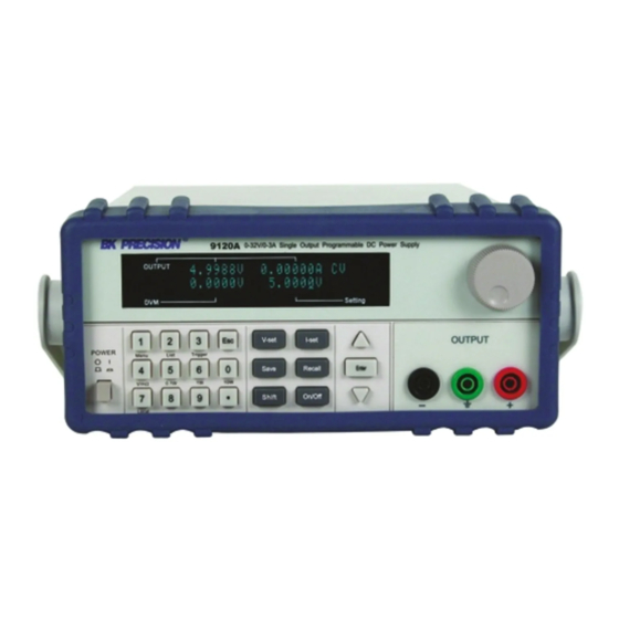
The first row displays the actual output voltage value and current and the state of power supply. The second row displays the voltage measured by the DVM (on left) and the Set Value for the voltage of the power supply. To obtain additional information about the instrument, press and hold the SHIFT button during Power Up. -
Page 9: Current Output Check
3) Set the voltage value Set a different voltage value. Make sure that the set value and output value are the same. Also check if the output current value is zero or close to zero A. 4) Ensure that the voltage can be adjusted from zero to the maximum rated value. Current Output Check The following steps check the basic current functionality by shorting the power supply’s output. -
Page 10: Adjusting The Carrying Handle
1.6 Adjusting the Carrying Handle To adjust the position, grasp the handle by the sides and pull outward. Then rotate the handle to the desired position. Dimensions: 214.5 mm (W) x 88.2 mm (H) x 354.6 mm (D) all units in mm For Models: 9120A, 9121A, 9122A, 9123A, 9124... -
Page 11: Rack Mounting The Instrument
For Models: 9150, 9151, 9152, 9153 1.7 Rack Mounting the Instrument You can mount the power supply in a standard 19-inch rack cabinet using the IT-E151 rack mount kit. Note: Remove the carrying handle and the two plastic ears before rack-mounting the instrument. To remove the handle, grasp the handle on the side, pull outwards and rotate it to a special position where the arrow on the handle and the arrow on the plastic ears are in opposite directions. -
Page 12: Front-Panel Operation
To rack mount a single instrument, order rack mount kit IT-E151 To rack mount two instruments (models 9120A, 9121A, 9122A, 9123A, 9124 only) side-by-side, order rack mount kit IT-E151, In this case you don’t need to use the front cover panel. 3. -
Page 13: Numerical Keys/Secondary Shift Functions
Numerical Keys/Secondary Shift Functions Shift Functions V/mΩ: Toggle between DVM and mΩ Meter mode 0.1 W: Set the range of the mΩ Meter to 0.1 W 1 W: Set the range of the mΩ Meter to 1 W 10 W: Set the range of the mΩ... -
Page 14: Front-Panel Operation Overview
▼:Down key Enter: Press to confirm numerical entries 3.2 Front-panel Operation Overview The power supply at shipment is preconfigured for front-panel operation. At power-on, the power supply will automatically start up in front panel operation mode. When the power supply is in remote operation mode, the front-panel is disabled. You can revert to Local mode, by pressing the Local button or by sending the appropriate SCPI command. -
Page 15: Menu Operation
to assign and store the current settings to the selected memory location To recall a setting Press the Recall key. Use the knob to scroll to the memory location where the settings you want to recall are ENTER stored. Press to recall and activate those settings You can also use the SCPI command:*SAV *RCL to save and recall respectively. - Page 16 None< Default > Even Address Set Set the communication address (range from 0 to 30) Address=** Port Mode Select mode of digital port Trigger< Def > RI/DFI Note: DFI is not available for models 9150, 9151, 9152, 9153 DIGITAL I/O Note: Digital output not available for models 9150, 9151, 9152, 9153 Trig Source...
-
Page 17: Menu Function
2 X 100 Steps 1 X 200 Steps Exit Out On Timer Output timer. If Timer State is set to ON, power supply output will turn off after the timer elapsed. Timer State Setting POWER ON timer state Enable Output Timer. Output will turn off after value set in menu “Timer Set”... - Page 18 TRIGGER: Pins 1 and 2 can be used to apply external trigger sources to the power supply. These pins can also be used to control the list operation RI/DFI: The Inhibit Input pin can be used to control the output state of the power supply (RI function). The Fault Output pin (DFI function) can be used to indicate internal faults of the power supply.
- Page 19 The RI input has 3 modes: LATCHING, LIVE and OFF LATCHING When the TTL signal at the RI port transitions from TTL High to Low, the output of the power supply will turn off. LIVE The output state of the power supply changes according to the signal level applied to the RI port. If the level is TTL high, the power supply output is on;...
- Page 20 Memory area Number of groups/ area Capacity/group 4KByte 2KByte 1KByte 512 Byte Example: Group C can store 4 groups, each group has a maximum capacity of 1KByte. The power supply executes a list in CONTINIOUS or Step mode. In CONTINIOUS mode, the power supply will start executing the list once.
- Page 21 Shift List Shift Trigger 16) Press to set the list file, then press to run the list Shift List file. Press to stop. If you have created several list files, you can call the list file that you need by “Call ListFile” function in the Shift List menu.
-
Page 22: Output Operation
3.7 Output Operation On/Off For front panel operation, press to enable/disable the output. If the power supply is in remote control mode, you can send SCPI command (OUTPut ON|OFF) to change the state of output. 3.8 Remote Sense and digital port functions 8 pin connector in rear panel (Models 9120A, 9121A, 9122A, 9123A, 9124) INH GND FLT GND 4 pin connector in rear panel (Models 9150, 9151, 9152, 9153) -
Page 23: Digital Volt Meter (Dvm)
LATCHING: When the level of INH port changes from high to low, the output of power supply turns off. LIVE: The output state of power supply changes according to the level of the INH port. If the level of INH is TTL High, the output is on. If the level at pin INH is TTL Low, the output of the power supply is off. -
Page 24: Milliohm Meter
Shift By default, the power supply is in DVM mode. Press followed by V/mΩ to toggle between Voltmeter and mΩ Meter mode. 3.10 Milliohm Meter The instrument is also equipped with a Milliohm Meter which can accurately measure resistance up to 10 Ω. To protect the resistor, make sure to select an appropriate power range before connecting it to the power supply. -
Page 25: Serial Adapter Cables
GPIB (model 9123A only) interface via a serial converter cable. This chapter describes how to use a computer to control the output of the power supply. 4.1 Serial adapter cables RS232 to TTL serial Converter cable IT-E131 The DB9 interface connector on the rear panel of the power supply provides a TTL level interface. Use the communication cable (IT-E131) to connect the DB9 interface connector of the power supply to the RS-232 interface connector of the computer IT-E131 communication cable... -
Page 26: Communication Between Power Supply And Pc
GPIB to TTL adapter IT-E135 (Model 9123A only) The DB9 interface connector on the rear panel of the power supply provides a TTL voltage level interface. Use the communication adapter IT-E135 to communicate via GPIB Power Supply Connect this connector to Connect this DB9 TTL side to your... - Page 27 Data Frame Format Parity=None Start Stop 8 Data Bits Parity=Odd, Start Parity Stop 8 Data Bits Even End of String character is ’\n’ (0x0a) DB9 Interface Details The DB9 connector in the rear panel of the power supply provides a TTL level signal .It can be connected to a standard PC interface via the IT-E131, IT-E132 or IT-E135 isolated converter/adapter.
-
Page 28: Scpi Command Overview
4.3 SCPI Command Overview Common IEEE488.2 Commands *CLS *ESE *ESE? *ESR? *IDN? *OPC *OPC? *PSC *PSC? *RST *SRE *SRE? *STB? *TRG *SAV *RCL Essential SCPI Commands SYSTem :ERRor[:NEXT]? :VERSion?, :ADDRess? :REMote :LOCal :RWLock STATus :QUEStionable [:EVENt]? :CONDition? :ENABle <VALUE> :ENABle? :OPERation :[EVENt]? : CONDition? - Page 29 [:DATA] {<numeric value>} :DVM :LEVel {<level>} [:DATA] {<numeric value>} :SAVe :INITital Output Commands OUTPut [:STATe] {<bool>} [:STATe]? :TIMer [:STATe] {<bool>} [:STATe]? :DATA {<timer>} :DATA? [SOURce:] MODE {<FIXed|LIST|DRM>} MODE? VOLTage [:LEVel] {<n>} [:LEVel]? :PROTection :STATe {<bool>} :STATe? [:LEVel] {<n>} [:LEVel]? CURRent [:LEVel] {<n>} [:LEVel]? LIST...
-
Page 30: Port Configuration Commands
:VOLTage[:DC]? :CURRent[:DC]? :POWer[:DC]? :DVM[:DC]? :RESistance[DC]? Port Configuration Commands [SOURce:] SYSTem : SENSe [:STATe] {<bool>} [:STATe]? PORT :FUNCtion {<TRIGger|RIDFi|DIGital>} : FUNCtion? :MODE {<OFF|LATChing|LIVE>} :MODE? :SOURce {<OFF|QUES|OPER|ESB|RQS>} :SOURce? DIGital :OUTPut[:STATe] {<bool>} :INPut[:STATe]? SENSe :RESistance: :RANGe {LOW | MIDdle | HIGH>} :RANGe? Trigger Command TRIGger [:IMMediate] :SOURce {<source>}... - Page 31 preliminary checkout. Execution error. Command parameter overflows or the condition is not right. Command error. Syntax or semantic error occurs when receiving information. Power on. It is 1when power supply is reset. Status byte register QUES If a quest enable condition changes, QUES is 1. If a standard event status enable register changes, ESB is 1.
-
Page 32: Scpi Command Description
4.4 SCPI Command Description Common IEEE488.2 Commands *CLS This command clears the following registers: Standard event status register Quest condition register Operation event register Status byte register Error code Command syntax: *CLS Parameter: None *ESE This command sets the parameter of the standard event enable register. - Page 33 XXXXXX product serial num ber VX.XX software version number For example: BK PRECISION,9120A,000004,V1.01 *OPC When all commands sent to the instrument prior to this command have been executed, OPC of the standard event status register will be set to 1.
-
Page 34: Essential Scpi Commands
Reference Command: *ESE *ESR? *PSC *STB? *STB? This command reads data from the status byte register. After executing this command, the status byte register is reset. Query syntax: *STB? Parameter: None Return parameter: <NR1> Reference command: *CLS *ESE *ESR Bit map of the standard event status enable register Bit Position Bit Name OPER... - Page 35 (60) Unmatched quo tation m ark ( s ingle/double) in pa rameters (65) Unmatched br a cket (70) Command keywords w ere not r e cognized (80) No entry in list to retrieve (number list or channel list) (90) Too m any di m ensions i n entry t o be r e turned in pa rameters (101) Command E xecution e rror (100)
- Page 36 Bit map of standard event status enable register Bit Position Bit name no use no use no use no use no use Bit Value STATus:QUEStionable:CONDition? This command queries the parameters of the quest condition register. When a bit of the quest condition changes, the corresponding bit value in the quest event register will be set to 1.
-
Page 37: Output Commands
Parameter: 0~255 Reset value: Consult *PSC command Example: STATus: OPERation:ENABle 128 Query syntax: STATus: OPERation:ENABle? Return parameter: <NR1> Reference command: *PSC Output Commands OUTPut[:STATe] This command sets the power supply output on or off. Command syntax: OUTPut[:STATe] <bool> Parameter: 0|1|ON|OFF *RST value: OFF Query syntax: OUTPut:STATe? Return parameter: 0|1... -
Page 38: List File Commands
Example: MODE FIX Query syntax: [SOURce:] MODE? Return parameter: <CRD> Usage: MODE FIX command can also be used to stop a list execution. [SOURce:]CURRent [:LEVel] This command sets the current value of the power supply. Command syntax: [SOURce:]CURRent [ : LEVel] <NRf> Parameter: MIN TO MAX|MIN|MAX Unit: A mA *RST value: MIN... - Page 39 STEP List o peration is step mode. Command syntax: [SOURce:]LIST:MODE <CRD> Parameter: CONTinious|STEP Query syntax: [SOURce:]LIST:MODE? Return parameter: <CRD> [SOURce:]LIST:STEP This command sets the operation mode of the list file. ONCE List operate once REPeat Repeat list operation Command syntax: [SOURce:]LIST:STEP <SRD> Parameter: ONCE|REPeat Query syntax: [SOURce:]LIST:STEP? Return parameter: <CRD>...
- Page 40 Parameter: None Example: LIST:CURR? 1; Return parameter: <NR2> [SOURce:]LIST :VOLTage[:LEVel] This command sets the voltage step. Command syntax: [SOURce:]LIST:VOLTage [:LEVel] <NRf> Parameter: 0~360V Unit: V mV Example: LIST:VOLT 1,3V; Query syntax: [SOURce:]TRANsition: VOLTage:TLEVel? Parameter: None Example: LIST:VOLT? ; Return parameter: <NR2> [SOURce:]LIST:WIDth This command sets the minimum step time.
- Page 41 Example: LIST:SAV 1 [SOURce:]LIST:RCL This command can recall the list file saved before from the register. Command syntax: [SOURce:]LIST:SAV <NR1> Parameter: 1~8 Example: LIST:SAV 1 [SOURce:]LIST:UNIT This command sets the unit for the list width in either seconds (SECOND) or milliseconds (MSECOND). Command syntax: [SOURce:]LIST:UNIT <second>...
-
Page 42: Interface Configuration Commands
HIGH: 1W resistance range Command syntax: SENSe:RESistance:RANGe Parameter: LOW | MIDdle | HIGH Example: RES:RANG LOW Query syntax: SENSe:RESistance:RANGe? Return parameter: <SRD> MEASure[:SCALar]:RESistance[:DC]? This command queries the resistance reading of the milliohm meter. Command syntax: MEASure[:SCALar]: RESistance? Parameter: None Return parameter: <NR2> Return parameter unit: Ohm Example: MEAS:RES? Interface Configuration Commands... -
Page 43: Trigger Commands
[SOURce:]DIGital:OUTPut[:STATe] This command sets the output state of the digital port. This command can be used when the mode of the port is set to DIGITAL. (Not available for models 9150, 9151, 9152, and 9153) Command syntax: SOURce:OUTPut[:STATe] Paremeter: OFF|ON|0|1 [SOURce:]DIGital:INPut[:STATe]? This command sets the input state of port. - Page 44 LIST:VOLT 2,4 LIST:UNIT SECOND LIST:WID 1,1 LIST:WID 2,2 LIST:NAME ‘TEST’ LIST:SAVE 1 MODE LIST TRIGGER...
-
Page 45: Specifications
5. Specifications 5.1 Specifications Models 9120A, 9121A and 9124 Parameter 9120A 9121A 9124 Voltage 0 - 32 V 0 - 20 V 0 - 72 V Output Ratings Current 0 - 3 A 0 - 5 A 0 - 1.2 A ( 0 °C~40 °C) LVP* 0 - 33 V... - Page 46 Voltage 0 - 60 V 0 - 30 V Output Ratings Current 0 - 2.5 A 0 - 5 A ( 0 °C~40 °C) LVP* 0 - 61 V 0 - 31 V Voltage Load Regulation <0.01%+2 mV ±(%of output+offset) Current <0.05%+0.5 mA <0.05%+1.5 mA...
-
Page 47: Supplemental Characteristics
Load Regulation Voltage <0.01% + 0.5 mV <0.01% + 1 mV <0.01% + 1 mV ±(%of output+offset) Current <0.1% + 10 mA <0.1% + 5 mA <0.1% + 2 mA Voltage <0.02% + 0.1 mV <0.02% + 1 mV <0.02% + 1 mV Line Regulation ±(%of output+offset) Current... - Page 48 1 year AC Input Ratings (selectable via switch on the rear panel) 220 AV±10%,47~63 Hz 110 AV±10%,47~63 Hz Maximum output power 9122A 9123A 9150 9151 9152 9153 9120A 9121A 9124 150 W 150 W 312 W 540 W 540 W 540 W 96 W 100 W...
- Page 49 SERVICE INFORMATION Warranty Service: Please go the support and service section on our website www.bkprecision.com to obtain a RMA #. Return the product in the original packaging with proof of purchase to the address below. Clearly state on the RMA the performance problem and return any leads, probes, connectors and accessories that you are using with the device.
- Page 50 22820 Savi Ranch Parkway Yorba Linda, CA 92887 www.bkprecision.com © 2010, 2009 B&K Precision Corp. Printed in China v092711...
Need help?
Do you have a question about the 9100 Series and is the answer not in the manual?
Questions and answers