Sign In
Upload
Download
Table of Contents
Contents
Add to my manuals
Delete from my manuals
Share
URL of this page:
HTML Link:
Bookmark this page
Add
Manual will be automatically added to "My Manuals"
Print this page
×
Bookmark added
×
Added to my manuals
Manuals
Brands
BK Precision Manuals
Power Supply
9130C Series
User manual
BK Precision 9130C Series User Manual
Triple output programmable dc power supplies
Hide thumbs
1
2
3
4
5
6
7
8
9
Table Of Contents
10
11
12
13
14
15
16
17
18
19
20
21
22
23
24
25
26
27
28
29
30
31
32
33
34
35
36
37
38
39
40
41
42
43
44
45
46
47
48
49
50
page
of
50
Go
/
50
Contents
Table of Contents
Troubleshooting
Bookmarks
Table of Contents
Safety Symbols
Table of Contents
General Information
Product Overview
Package Contents
Product Dimensions
Rackmount Installation
Front Panel Overview
Rear Panel Overview
Keypad Overview
Display Overview
Getting Started
Input Power and Fuse Requirements
Fuse Requirements
Line Voltage Selection
Output Connections
Carrying Handle Adjustment
Preliminary Check
Front Panel Operation
Check Model and Firmware Version
Output Control
Meter Mode
Setting Voltage and Current
Over Voltage Protection (OVP)
Save/Recall Instrument Settings
Key Lock
Output Check
Menu Access and Options
How to Access the Menu
Menu Options
Output Power-On State
Output Parameters
Lock/Unlock Rotary Knob
Buzzer On/Off
Communication
Memory Group
Protocol
Return Meter
System Menu
Combined Series and Parallel Modes
Tracking Mode
Parameters in Series/Parallel Mode
Over Temperature Protection
Remote Sense
Remote Operation
Interface Configuration
Remote Commands
Troubleshooting Guide
Specifications
Calibration
Service Information
Limited Three-Year Warranty
Advertisement
Quick Links
1
Remote Operation
2
Remote Commands
Download this manual
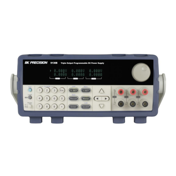
9130C Series
Triple Output Programmable DC Power
Supplies
Models: 9130C, 9131C, 9132C
USER MANUAL
i
Table of
Contents
Previous
Page
Next
Page
1
2
3
4
5
Advertisement
Table of Contents
Need help?
Do you have a question about the 9130C Series and is the answer not in the manual?
Ask a question
Questions and answers
Related Manuals for BK Precision 9130C Series
Power Supply BK Precision 9130 Instruction Manual
Triple output programmable dc power supply (48 pages)
Power Supply BK Precision 9130B User Manual
9130b series triple output programmable dc power supplies (50 pages)
Power Supply BK Precision 9132B User Manual
9130b series triple output programmable dc power supplies (50 pages)
Power Supply BK Precision 9131B User Manual
9130b series triple output programmable dc power supplies (50 pages)
Power Supply BK Precision 9131C User Manual
Triple output programmable dc power supplies (50 pages)
Power Supply BK Precision 9132C User Manual
Triple output programmable dc power supplies (50 pages)
Power Supply BK Precision 9115-AT User Manual
Multi-range dc power supply (79 pages)
Power Supply BK PRECISION 9115 User Manual
Multi-range dc power supply (74 pages)
Power Supply BK Precision 9120 Instruction Manual
Single output programmable dc power supply (96 pages)
Power Supply BK Precision 9110 User Manual
Multi range dc power supply (23 pages)
Power Supply BK Precision 9120A User Manual
Single output programmable dc power supply (50 pages)
Power Supply BK Precision 9103 User Programming Manual
Switching dc power supplies (9 pages)
Power Supply BK Precision 9129B User Manual
Triple output programmable dc power supply (46 pages)
Power Supply BK Precision 9140 Series User Manual
Triple output multi-range dc (82 pages)
Power Supply BK Precision 9140 Series User Manual
Triple output multi-range вс power supplies (98 pages)
Power Supply BK Precision 9171B User Manual
Programmable dc power supplies (190 pages)
This manual is also suitable for:
9131c
9132c
Bk9130b
Bk9131b
Bk9132b
Table of Contents
Print
Rename the bookmark
Delete bookmark?
Delete from my manuals?
Login
Sign In
OR
Sign in with Facebook
Sign in with Google
Upload manual
Upload from disk
Upload from URL


Need help?
Do you have a question about the 9130C Series and is the answer not in the manual?
Questions and answers