BK Precision 9115 User Manual
Multi range dc power supply
Hide thumbs
Also See for 9115:
- Programming manual (23 pages) ,
- User manual (74 pages) ,
- User manual (79 pages)
Table of Contents
Advertisement
Quick Links
Advertisement
Table of Contents

Related Manuals for BK Precision 9115


Summary of Contents for BK Precision 9115
- Page 1 Model: 9115 Multi Range DC Power Supply USER MANUAL...
-
Page 3: Safety Summary
Safety Summary The following safety precautions apply to both operating and maintenance personnel and must be observed during all phases of operation, service, and repair of this instrument. Before applying power, follow the installation instructions and become familiar with the operating instructions for this instrument. - Page 4 WARNING: Do not alter the ground connection. Without the protective ground connection, all accessible conductive parts (including control knobs) can render an electric shock. The power jack and mating plug of the power cable meet IEC safety standards. WARNING: To avoid electrical shock hazard, disconnect power cord before removing covers. Refer servicing to qualified personnel.
- Page 5 Compliance Statements Disposal of Old Electrical & Electronic Equipment (Applicable in the European Union and other European countries with separate collection systems) This product is subject to Directive 2002/96/EC of the European Parliament and the Council of the European Union on waste electrical and electronic equipment (WEEE) , and in jurisdictions adopting that Directive, is marked as being put on the...
-
Page 6: Ce Declaration Of Conformity
CE Declaration of Conformity The power supply meets the requirements of 2006/95/EC Low Voltage Directive and 2004/108/EC Electromagnetic Compatibility Directive with the following standards. Low Voltage Directive EN61010-1: 2001 EMC Directive EN 61000-3-2: 2006 EN 61000-3-3: 1995+A1: 2001+A2: 2005 EN 61000-4-2 / -3 / -4 / -5 / -6 / -11 EN 61326-1: 2006... -
Page 7: Safety Symbols
Safety Symbols Refer to the user manual for warning information to avoid hazard or personal injury and prevent damage to instrument. Chassis (earth ground) symbol. On (Supply). This is the AC mains connect/disconnect switch on the front of the instrument. Off (Supply). -
Page 8: Table Of Contents
Table of Contents General Information ................... 10 Product Overview ......................10 Package Contents ......................10 Product Dimensions ....................... 11 Front Panel Overview ..................... 11 Front Panel Description ......................12 Rear Panel Overview ...................... 13 Rear Panel Description ......................13 Display Overview ......................14 Display Description ........................ - Page 9 Restore Factory Default Settings ................... 26 Configure Power-On State ..................... 26 Configure Trigger Source ....................... 27 Save/Recall Instrument Settings ................... 27 Enable/Disable Key Sound ..................... 29 Remote Interface Setup ......................29 Return Meter ......................... 32 CONFIG Menu ......................... 32 Load Setup Option ......................... 32 External Analog Control ......................
-
Page 10: General Information
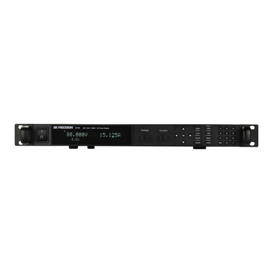
1 General Information 1.1 Product Overview B&K Precision 9115 is a multi range single output high power supply with the capability of producing up to 80 V or 60 A at a maximum power output of 1200 W. With an easy-to-read VFD display, user-friendly controls and a numeric keypad, it allows for easy configurations from the front panel. -
Page 11: Product Dimensions
1.3 Product Dimensions The power supply’s dimensions are approximately: 415mm (16.3 in) x 44 mm (1.7 in) x 500 mm (19.7 in) (WxHxD). It is designed to fit in a standard 19-inch rackmount and is of 1U size. Figure 1 - Front Panel View Figure 2 - Side View 1.4 Front Panel Overview 6 7 8... -
Page 12: Front Panel Description
Front Panel Description Power On/Off switch VFD display Voltage adjust knob Current adjust knob Up/Down/Left/Right arrow keys Used to adjust cursor location and selecting menu items. On/Off / Lock button Control the output state or locks the front panel button. Save/Recall button Used to save and recall instrument settings. -
Page 13: Rear Panel Overview
1.5 Rear Panel Overview Figure 4 - Rear Panel Rear Panel Description Analog control interface Output terminal Rear cooling fan GPIB interface USB interface RS-232 interface AC input receptacle Fuse box RS-485 interface Remote Sense terminals... -
Page 14: Display Overview
1.6 Display Overview OFF CC CV Addr Error Trig Prot * Shift 80.000V 12.000A = 85.000 V 0.0 W Display Description Setting/Measured Voltage Measured Power Output Settings Display Displays parameter settings such as OVP, P-max, Rise/Fall Setting/Measured Current Indicates output is disabled Indicates constant current (CC) operation Indicates constant voltage (CV) operation Indicates remote mode... -
Page 15: Getting Started
2 Getting Started Before connecting and powering up the instrument, please review and go through the instructions in this chapter. 2.1 Input Power and Fuse Requirements Input Power The supply has a universal AC input that accepts line voltage input within: Voltage: 115 V (+/-10%) or 230 V (+/- 10 %) Frequency: 47 Hz –... -
Page 16: Output Connections
2. Use a flat blade screwdriver and turn the fuse capsule counter-clockwise. There is an internal spring that will push it out after turning a few times. 3. Pull out the glass tube fuse inside to check and replace as necessary. 4. -
Page 17: Preliminary Check
WARNING: Before connecting wires to the output terminals, turn OFF the power supply to avoid damage to the instrument and the device under test (DUT). For safety, load wires must have a wire gauge size large enough to prevent overheating when the power supply operates at maximum short circuit output current. -
Page 18: Output Check
If any of these errors occur, please contact B&K Precision. Output Check Voltage Check Follow the steps below to check basic voltage output with no load connected. 1. Turn on the power supply. The display will show the OFF annunciator above the voltage display. -
Page 19: Check Model And Firmware Version
Power Info . . . Model : BK9115 Ver: 0.02 – 0.01 3. The model is shown above as BK 9115, and the firmware version is shown as 0.02 – 0.01. 4. Press twice to exit the menu and return to the normal display. -
Page 20: Front Panel Operation
3 Front Panel Operation 3.1 Menu Options All settings and parameters can be configured from the built-in menu system of the power supply. To access the menu, press and press The menu system is divided into 4 sections and are organized as follows: SYSTEM Initialize Reset power supply settings to factory default values. -
Page 21: Configure Voltage And Current Output
SYSTEM MENU In it i al i ze Powe r-O n 5. The selected item will be blinking. Use keys to move through the menu items. When there is a on the right side of the display, that means there are more menu items available to select from. -
Page 22: Setting Current
Setting Current Follow the steps below to set the output current: 1. From the normal front panel display, users can use either the current adjust knob or the numeric keypad to enter the setting current. 2. If entering using numeric keypad, press first so that the cursor selects the current display. - Page 23 WARNING: DO NOT disconnect the wires if remote sense is not used. Doing so will cause erratic behavior and may damage the power supply under certain conditions. Never connect any power source into any of the four terminals at any time during operation.
-
Page 24: Protection Settings
WARNING: DO NOT at any time disconnect the wires from the Vs+ and Vs- terminals to the DUT while output is enabled (ON). Doing so may damage the power supply and cause unstable output. 3.3 Protection Settings Configure Over Voltage Protection (OVP) Follow the steps below to set the OVP limit: 1. -
Page 25: Configure Maximum Power Limit
Configure Maximum Power Limit Follow the steps below to set the maximum power limit: 1. Press and then . The display will show P on the bottom right. Use the voltage or current adjust knob or the numeric keypad to enter the maximum power output limit. -
Page 26: Restore Factory Default Settings
Restore Factory Default Settings All instrument settings can be reset back to their factory default values by doing the following: WARNING: Restoring the instrument to factory default will change all current instrument settings and parameters back to their default values. 1. -
Page 27: Configure Trigger Source
4. To exit the menu at any time, press twice. Configure Trigger Source The trigger function is used to initiate the start of running a program sequence (list). The trigger source can be set so that users can send a trigger from the front panel or through a remote command via remote interface. - Page 28 Save Settings 1. Set up all the instrument settings that you want to save. 2. Then, press . The display will show the following: 80.000V 12.000A S ave D ata to B ank : 0 3. Use the current adjust knob or the numeric keypad to enter the memory location in which to store current instrument settings.
-
Page 29: Enable/Disable Key Sound
Enable/Disable Key Sound The instrument initially has key sound enabled from factory. To disable or re-enable the key sound, follow the steps below: 1. From the SYSTEM menu, browse and select Buzzer and press 2. Select between the two options: On(Def) –... - Page 30 4. Use to select between each serial settings, and use to change the settings. 5. Below list the options that can be changed for each setting: Baudrate: 4800, 9600, 19200, 38400, 57600, 115200* Data bits: 8 Parity: N (None), E (Even), O (Odd) Stop bit: 1, 2 Addr: 0 to 31 Note: The default is 4800, 8, N, 1, Address = 0.
- Page 31 RS-485 Multiple power supplies (up to 31) can be connected together in series and be controlled via the DB-9 RS-485 interface. 1. From the SYSTEM menu, browse and select Communication and press 2. Select RS485 and press to set to RS485 for remote communication. The following display will be shown: RS485 48 00 , 8 , N , 1 , Add r .
-
Page 32: Return Meter
Return Meter This option allows users to enable an internal fixed timer delay (5 seconds) for the power supply to automatically switch from setting display to measured display. When enabled, if the power supply output state is ON (enabled) and if the display shows setting voltage and current, it will automatically switch to measured voltage and current display after 5 seconds. -
Page 33: External Analog Control
WARNING: DO NOT enable this function for battery test applications (i.e. battery charging) and all applications that may have a high charge. If a battery with a low voltage is connected to the power supply while the output is OFF (disabled), the dummy load will drain the battery. - Page 34 2. Select 10v-M or 5v-M so that it is blinking. Use the keys to change between 10v- M and 5v-M. – 0 – 5 V scale is used for monitoring 0 – 100% of output. 10v-M – 0 – 10 V scale is used for monitoring 0 – 100% of output. 3.
- Page 35 1. From the CONFIG menu, browse and select Ext-Ctrl and press . The following screen will display: Ext – Ctrl Setup 1 0v- M 10v /10 k-P V- P Of f 2. Select the third item V-P or R-P so that it is blinking. Use the keys to change between V-P or R-P.
- Page 36 DGND Ground pin EXT ON Control output state SHUT_OFF Emergency shut off POWER_OK Status output CV_CC+ CV mode status CV_CC- CC mode status VPRG Voltage programming input REF_10V 10V DC reference output IPRG Current programming input VMON Voltage monitoring output IMON Current monitoring output AGND...
- Page 37 Power Supply Status The power supply status can be monitored using POWER_OK (pin 16) output and DGND (pin 1). During normal operating conditions, this pin will output 5 VDC. If OTP condition or other abnormalities occur, this pin will output 0 VDC. Monitoring Operation Mode The operation mode of the power supply can be monitored using CV_CC+ (pin 18) and CV_CC- (pin 19) output pins.
-
Page 38: Configure Voltage Limit
Parallel/Series Connection Up to three 9115 power supplies can be connected together in a parallel or series connection setup. The power supplies can be set up for master/slave mode so that the master unit can control all other power supplies in the parallel/series connection. -
Page 39: Connection And Setup
to function. Connection and Setup Connecting multiple power supplies in parallel or in series can increase the overall current output or voltage output respectively. For this configuration to function properly, there are several items that must be set up first. Follow the instructions in this section carefully for setup. Connection Determine the total number of power supplies that you want to connect in parallel or series. - Page 40 Master/Slave Setup Only one power supply has to be configured as a Master. The rest must be configured as Slave. Up to 3 units can be configured in total. Note: Configure Slave power supplies FIRST, and configure the Master power supply LAST.
-
Page 41: Program Sequence Mode (List Mode)
1. From the CONFIG menu, select Online and press . The following will display: Online Setup Paral le l S l ave Add r… Of f 2. While Parallel or Series is flashing, use keys to toggle between the two options. Set to Parallel for parallel connection and Series for series connection. -
Page 42: Configure Sequence Parameters
Sequence #1 Program #1 Step 1.. Sequence #1 Step 2.. Sequence #2 Save Step 10.. Sequence #10 Program # Memory Program #10 Sequence #10 Recall Sequence #2 Step 1.. Sequence #5 Step 2.. Sequence #7 Sequence #8 Step 10.. There are three separate configurations to set up for programming and running a sequence (in order): 1. - Page 43 Table 3 - Step Parameter Range Parameter Adjustable Range Voltage Setting 0.000 – < OVP Voltage Current Setting 0.000 – *max. current setting Width 0.001 seconds – 86400 seconds Slope 0.002 seconds – 86400 seconds *Maximum current and voltage setting cannot exceed maximum power configured under P-max setting. As an example, follow the steps below to set up a sequence with fixed current limit of 1 A, as illustrated below: 1.
- Page 44 A c ti ve Step: 09876 54321 5. These numbers represent the step numbers of the sequence, where “0” represents step number 10. At this point, use the numeric keypad and try to push any numbers 0 – 9. Notice that the number you press will correspond to the number displayed in Active Step and will toggle to display a “Y”...
- Page 45 9. This is prompting the user to enter the voltage setting for step 1. Use the voltage and current adjust knob or the numeric keypad and enter 1.000. Then press 10. The display will change to the following, prompting the user to enter the current setting for step 1.
-
Page 46: Configure Program (List)
SAVE SEQ 16. If stored successfully, the display will show a message Save Success! After a few seconds, it will return to the LIST menu. Configure Program (List) The sequence(s) to execute and run can be selected, as well as its repetitiveness. This means multiple sequences can be run one after another. - Page 47 EDIT LIST POWER L ist Powe r = 120 0.0 W 3. This parameter is configured to limit the maximum power of the program (list) when it is executed. Leave it default to 1200.0 for maximum power output. Press and the following will display: EDIT LIST REPEAT L ist Re pe at = 1...
-
Page 48: Recall And Run Program
FILE A c ti ve Seq : 0 987654 3YY 8. Once these two sequences are selected (active), press to see the following: SEQ REPEAT S eq 1 Repe at : 9. The display prompts the user to enter the number of times to repeat sequence #1 as part of the program (list). - Page 49 1. From the LIST menu, use the key to select Recall and press . The display will say RECALL LIST with the prompt Recall List File: to ask to enter a number. 2. This is the location number where the program is stored in. Select a number between 1 to 10 with the current adjust knob or the numeric keypad, then press 3.
-
Page 50: Configure Voltage Slope
3.6 Configure Voltage Slope The power supply has the capability of controlling the slope of the output voltage during changes between voltage settings. Timings can be configured for both the rising and falling edge between voltage output transitions. To illustrate this feature and provide configuration instructions, follow the example below. Suppose you want to simulate the voltage signal below by manually setting the voltage from 5 V to 10 V over a span of 5 seconds, then manually changing it to 1 V and have it decrease from 10 V to 1 V over a span of 10 seconds. -
Page 51: Key Lock
2. T is the rising edge time for an output voltage transition. Use the numeric keypad or rise the current adjust knob and enter 5.000 s (5 seconds). 3. Press and T will be displayed. T is the falling edge time for an output voltage fall fall transition. -
Page 52: Remote Operation
4 Remote Operation 4.1 Interface Connection RS-232 For RS-232 connectivity, refer to the diagram below for pinout information. The RS-232 is labeled in the rear panel and it is a female DB-9 interface. Description Transmit Data Receive Data A straight pin-to-pin DB9 female to DB9 male serial cable is required for using the RS-232 interface. -
Page 53: Rs-485
RS-485 For multi-unit configuration and control, the male DB-9 interface labeled RS-485 in the rear panel is used. The figure below illustrates the connection pins and description. Note: Pin 1 is used as the B pin (+) (non-inverting). Pin 5 is used as the A pin (-) (inverting). SC (reference) pin is not used. -
Page 54: Troubleshooting Guide
5 Troubleshooting Guide Below are some frequently asked questions and answers. Please check if any apply to your power supply before contacting B&K Precision. General Q: I cannot power up the power supply. Check that the power cord is securely connected to the AC input and there is live power from your electrical AC outlet. -
Page 55: Specifications
23 °C ± 5 °C. Specifications are subject to change without notice. Environmental Conditions: This power supply is designed for indoor use and operated with maximum relative humidity of 95%. Model 9115 Voltage 0 – 80 V Output Rating Current 0 – 60 A... - Page 56 To ensure the most current version of this manual, please download the latest version here: http://www.bkprecision.com/search/9115 For current up-to-date product information, please visit www.bkprecision.com...
-
Page 57: Calibration
7 Calibration We recommend a calibration interval of once per year to ensure that the power supply meets specifications. The instrument features closed-case calibration, however it is done remotely via the remote interface. -
Page 58: Service Information
SERVICE INFORMATION Warranty Service: Please go to the support and service section on our website at www.bkprecision.com to obtain a RMA #. Return the product in the original packaging with proof of purchase to the address below. Clearly state on the RMA the performance problem and return any leads, probes, connectors and accessories that you are using with the device. -
Page 59: Limited One-Year Warranty
LIMITED ONE-YEAR WARRANTY B&K Precision Corp. warrants to the original purchaser that its products and the component parts thereof, will be free from defects in workmanship and materials for a period of one year from date of purchase. B&K Precision Corp. will, without charge, repair or replace, at its option, defective product or component parts. Returned product must be accompanied by proof of the purchase date in the form of a sales receipt. - Page 60 22820 Savi Ranch Parkway Yorba Linda, CA 92887 www.bkprecision.com © 2013 B&K Precision Corp. Printed in China v021813...
Need help?
Do you have a question about the 9115 and is the answer not in the manual?
Questions and answers