
Related Manuals for BK Precision 9140 Series


Summary of Contents for BK Precision 9140 Series
- Page 1 GlobalTestSupply www. .com Find Quality Products Online at: sales@GlobalTestSupply.com...
- Page 2 Safety Summary The following safety precautions apply to both operating and maintenance personnel and must be followed during all phases of operation, service, and repair of this instrument. Before applying power to this instrument: • Read and understand the safety and operational information in this manual. •...
- Page 3 Category IV (CAT IV): Measurement instruments whose measurement inputs are meant to be connected to the primary power entering a building or other outdoor wiring. Do not use this instrument in an electrical environment with a higher category rating than what is specified in this manual for this instrument.
- Page 4 Unless otherwise stated, a ground connection on the instrument’s front or rear panel is for a reference of potential only and is not to be used as a safety ground. Do not operate in an explosive or flammable atmosphere. Do not operate the instrument in the presence of flammable gases or vapors, fumes, or finely-divided particulates.
- Page 5 it as not to be operated, and return the instrument to B&K Precision for repair. Notify B&K Precision of the nature of any contamination of the instrument. Clean the instrument only as instructed Do not clean the instrument, its switches, or its terminals with contact cleaners, abrasives, lubricants, solvents, acids/bases, or other such chemicals.
- Page 6 the power line before replacing fuses. Replace fuses only with new fuses of the fuse types, voltage ratings, and current ratings specified in this manual or on the back of the instrument. Failure to do so may damage the instrument, lead to a safety hazard, or cause a fire. Failure to use the specified fuses will void the warranty.
- Page 7 Safety Symbols Symbol Description Indicates a hazardous situation which, if not avoided, will result in death or serious injury. Indicates a hazardous situation which, if not avoided, could result in death or serious injury. Indicates a hazardous situation which, if not avoided, will result in minor or moderate injury.
-
Page 8: Table Of Contents
Contents Introduction Product Overview Contents Features Dimensions Rackmount Installation Front Panel Display Rear Panel Getting Started Input Power and Fuse Requirements Fuse Requirements Check or Replace Fuse Preliminary Check Self test Errors Basic Front Panel Operation Keys 3.1.1 Main Keys 3.1.2 Soft Keys 3.1.3... - Page 9 4.2.5 On/Off Delay Operating Mode and Coupling 4.3.1 Normal Mode 4.3.2 Series Mode List Mode List Setup Edit List 5.2.1 Load/Save List 5.2.1 List Number 5.2.2 Next 5.2.3 Repeat 5.2.4 Steps List Run Data Logger Using the Data Logger Function Parameters 6.2.1 Sampling Interval...
- Page 10 7.5.2 Security Error Log Help On Screen Help Key Lock Save/Recall Save the Output Settings Recall the Instrument’s Settings Power-On Settings Screenshot 10 Calibration Adjustment Procedure 10.1 Voltage Calibration Adjustment 10.2 Current Calibration Adjustment 10.3 OVP Calibration Adjustment 10.4 OCP Calibration Adjustment 10.5 RTC Calibration Adjustment 11 Performance Verification...
-
Page 11: Introduction
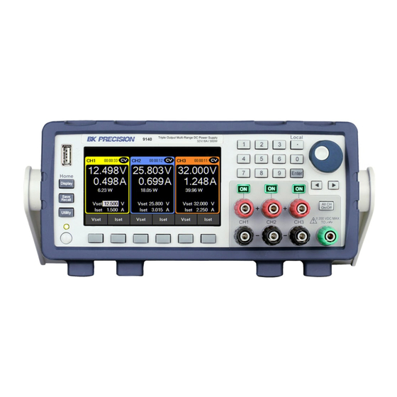
9141: 60 V / 4 A / 300 W Figure 1.1 Front View The 9140 Series triple output multi-range DC power supplies combine industry-leading power density and performance with an extensive set of features in a compact 2U form factor. -
Page 12: Contents
Introduction 1.2 Contents Please inspect the instrument mechanically and electrically upon receiving it. Unpack all items from the shipping carton, and check for any obvious signs of physical damage that may have occurred during transportation. Report any damage to the shipping agent immediately. Save the original packing carton for possible future reshipment. -
Page 13: Dimensions
Introduction • USB (USBTMC-compliant) and LXI compliant LAN interfaces standard, GPIB optional • LabVIEW , IVI-C, and IVI.NET drivers provided �� �� 1.4 Dimensions The 9140 power supply’s dimensions are approximately: 213 mm (8.4 in) x 88.2 mm (3.47 in) x 330 mm (13 in) (W x H x D). Figure 1.2 Dimensions GlobalTestSupply www. -
Page 14: Rackmount Installation
Introduction 1.5 Rackmount Installation The 9140 Series is compatible with the optional 19-inch rackmount kit model RK2US. The RK2US installation instructions can be downloaded from bkprecision.com Figure 1.3 Dimensions GlobalTestSupply www. .com Find Quality Products Online at: sales@GlobalTestSupply.com... -
Page 15: Front Panel
Introduction 1.6 Front Panel Figure 1.4 Front Panel Item Name Description Power Button Power the instrument ON or OFF Function Keys See section for details. USB Host Port USB port used to connect flash drives. Display Visual presentation of the device function and measurements. Numeric Keypad Used to enter precise values. -
Page 16: Display
Introduction 1.7 Display Icon Description The output is disabled. The output is enabled and in constant voltage mode The output is enabled and in constant current mode Data loggin is enabled but not recording. Data logging is enabled and recording. The instrument is connected to a network. -
Page 17: Rear Panel
Introduction 1.8 Rear Panel Figure 1.5 Rear Panel Item Name Description Rear panel output with remote sense. Internal relays switch between Output/Sense local and remote sensing. Kensington Lock the instrument to a fixed location using the security lock via the security slot lock hole. -
Page 18: Getting Started
Getting Started Before connecting and powering up the instrument, please review and go through the instructions in this chapter. 2.1 Input Power and Fuse Requirements The supply has a universal AC input that accepts line voltage input within: 9140 9141 AC Line Input 100 - 240 VAC 10%, 47 to 63 Hz... -
Page 19: Fuse Requirements
Getting Started 2.2 Fuse Requirements An AC input fuse is necessary when powering the instrument. The below table shows the fuse required for all models. Model Fuse Specification 9140 3.15 AT, 250 V 9141 3.15 AT, 250 V 2.3 Check or Replace Fuse For safety, no power should be applied to the instrument while changing line voltage operation. - Page 20 Getting Started Any disassembling of the case or changing the fuse not performed by an authorized service technician will void the warranty of the instrument SHOCK HAZARD: Hazardous voltages may exist at the outputs and the load connections when using a power supply with a rated output greater than 60 V.
-
Page 21: Preliminary Check
Getting Started 2.4 Preliminary Check Complete the following steps to verify the Power supply is ready for use. Verify and check to make sure proper AC voltages are available to power the Verify AC instrument. The AC voltage range must meet the acceptable specification as Input Voltage explained in section “2.1 Input Power and Fuse... -
Page 22: Self Test Errors
Getting Started Figure 2.3 Home Display 2.5 Self test Errors The following errors will be displayed if the self-test did not complete successfully: Error Message Description EEPROM Fail The internal EEPROM is corrupted or damaged. System Lost Last system settings within the EEPROM are lost. Module Fail Channel response failure. -
Page 23: Basic Front Panel Operation
Basic Front Panel Operation At power-on, the power supply will automatically enter the front-panel operation mode and the instrument can be controlled via the front panel keys and knob. 3.1 Keys 3.1.1 Main Keys There are three main keys: Navigates the 5 available screens. Opens up a menu giving access Opens the main menu bar. -
Page 24: Soft Keys
Basic Front Panel Operation 3.1.2 Soft Keys The unit has six soft keys, which are located beneath the screen. Each key selects the corresponding function. Functions will vary depending on the current menu or display. Figure 3.1 Soft Keys 3.1.3 Numeric Keys The numeric keys allow the configuration of various parameters. -
Page 25: Display
Basic Front Panel Operation 3.2 Display These power supplies have three main display modes: three channel display, single channel display, and live output monitoring display. Press the button to cycle between the different display modes or to return home when viewing any other menu. Three Channel Display Provides information of the outputs’: Allows configuration of:... - Page 26 Basic Front Panel Operation Single Channel Display Provides information of the outputs’: Allows configuration of: • State • Vset • Run time • Iset • Voltage • Vmax/Vmin • Current • OVP/OCP • Power • OnDelay/OffDelay • Vmax/Vmin • OVP/OCP •...
- Page 27 Basic Front Panel Operation Live Output Monitoring The live output monitoring display shows metered output voltage and current over time. It is always active and will continuously plot and overwrite the oldest value when the display graph is full. Live Output Monitoring Display Figure 3.5 The Live output display can be configured by setting the: Voltage, Current, and Time Scale.
-
Page 28: Check Model And Firmware Version
Basic Front Panel Operation Time Scale The time scale of each output can be set from 1 s/Div up to 10 min/Div. 1. While in Live Output Display use the softkeys to select Time Scale. 2. Use the rotary knob to navigate through the available scales. Voltage Offset A voltage offset can be added to each output. -
Page 29: Setting Voltage And Current
Basic Front Panel Operation 3.4 Setting Voltage and Current Follow the steps below to set the output voltage or current. The values can be entered using the numeric keypad or the rotary knob. 1. Using the keypad: Use the soft keys to select the channel VSET or ISET settings beneath channel view on the display. -
Page 30: Output Configuration
Output Configuration 4.1 Protection Settings 4.1.1 Over Voltage Protection (OVP) Over voltage protection is always enabled, however the user can set the OVP voltage limits. 1. Press the button then use the soft keys to select Output config > Protection settings 2. -
Page 31: Vmax/Vmin
Output Configuration 4.1.4 Vmax/Vmin Configure the maximum or minimum voltage value the user can set from the protection settings. 1. Press the button then use the soft keys to select Output config > Protection settings 2. Use the soft keys to select a channel to adjust. 3. -
Page 32: Output Timer
Output Configuration Never connect any power source into any of the terminals at any time during operation. When output is enabled, DO NOT use your hands to touch the terminals or the screws that are designed to tighten wires to the terminals. Doing so may create a shock hazard under high voltage output conditions. -
Page 33: Voltage Slew
Output Configuration 4.2.3 Voltage Slew The rising voltage slew rate can be set in volts per second. The voltage slew range can be set from 0.001 V/s to 3200.0 V/s. 1. Press the button then use the soft key to select Output config > Output Settings. 2. -
Page 34: Operating Mode And Coupling
Output Configuration 4.3 Operating Mode and Coupling Set the operation mode or coupling. Press the button then use the soft key to select Output Config > Op. Mode/Coupling > Operation Mode. 4.3.1 Normal Mode Sets operation mode to Normal. Normal mode sets the instrument to operate as a true triple output power supply. Press the button then use the soft key to select Output Config >... - Page 35 Output Configuration In Normal mode the main page will display the three outputs. Toggles through CH1, CH2, CH3, and live output monitoring display. Figure 4.3 Normal Mode Main Page Single CH displays more information about the output, and allows configuration of more parameters. Figure 4.4 Single Channel GlobalTestSupply www.
-
Page 36: Series Mode
Output Configuration 4.3.2 Series Mode Set operation mode to Series. Series mode changes the UI to accurately represent the possible outputs configurations. Series mode does not internally wire the outputs. The outputs must be connected externally to increase the available voltage range. Press the button then use the soft key to select Output Config >... - Page 37 Output Configuration CH1 + CH2 Operation mode will be set to Series 1 + 2. Changing operation mode will undo previous coupling configuration. Press the button then use the soft key to select Output Config > Op. Mode/Coupling > Operation Mode >...
- Page 38 Output Configuration Single CH displays more information about the output, and allows configuration of more parameters. The voltage configurations will now range from 0 v to 64 V for model 9140 and 0 V to 120 V for model 9141. Figure 4.7 Series CH1+2 Single Channel Display Protection Setting menu will also adjust the configurable values.
- Page 39 Output Configuration Series All Operation mode will be set to Series All. Coupling will not be available in Series All mode. Press the button then use the soft key to select Output Config > Op. Mode/Coupling > Operation Mode > Series > Series All. Figure 4.9 Series All In Series All mode will only toggle between the Series All display and live output monitoring.
- Page 40 Output Configuration Parallel Mode Set operation mode to Parallel. Parallel Mode does not internally wire the outputs. The outputs must be connected externally to increase the available current range. Parallel Mode changes the UI to accurately represent the possible output configurations. Press the button then use the soft key to select Output Config >...
- Page 41 Output Configuration CH1 + CH2 Operation mode will be set to Parallel 1 + 2. Selecting an operation mode will undo previous coupling configuration. Press the button then use the soft key to select Output Config > Op. Mode/Coupling > Operation Mode >...
- Page 42 Output Configuration The Single CH display will adjust to allow current configuration between .030 A to 16 A for model 9140 and .030 A to 8 A for model 9141. Figure 4.13 Parallel CH 1+2 Single Channel Display Protection Setting menu will also adjust the configurable range of each parameter. Figure 4.14 Parallel CH 1+2 Protection Settings GlobalTestSupply www.
- Page 43 Output Configuration Parallel All Operation mode will be updated based on selected mode. Coupling is not available. Figure 4.15 Parallel All Operation Mode In Parallel All Mode the button will only toggle between the Parallel All display and live output monitoring.
- Page 44 Output Configuration Figure 4.17 Parallel All Main Page Tracking Voltage levels are tracked on either CH1+2 or All Channels. Press the button then use the soft key to select Output Config > Op. Mode/Coupling > Operation Mode > Tracking. Tracking mode allows real time voltage tracking across all channels or between CH1 and CH2. When tracking mode is enabled, list mode will still operate independently on the channel that has list enabled.
- Page 45 Output Configuration Coupling Enable or disable the output coupling between multiple output channels, by using the soft keys to toggle individual channel coupling On or Off. Press the button then use the soft key to select Output Config > Op. Mode/Coupling If coupling is enabled, will follow the coupling settings.
- Page 46 Output Configuration Output Sequencing Figure 4.20 Sequencing Combine CH Coupling with Output On and Off Delay to toggle the outputs in a set sequence. To configure a sequence: 1. Set voltage and current output of the participating channels. Reference section Setting Voltage and Current.
-
Page 47: List Mode
List Mode The 9140 and 9141 are capable of storing up to 10 programmable lists in the internal memory. Each list can have up to 100 configurable steps. List memory is shareable across all 3 channels, allowing the channels to run the same list or different list simultaneously. - Page 48 List Mode List State: Toggle list state On/Off for the selected channel. List Number: Select a list program from the memory to run on the channel. Use the numeric keypad or rotary knob to select list number. Press to assign the list to a channel. Pace: Set the pace in which steps are executed.
-
Page 49: Edit List
List Mode b. Digital IO: Select to use the digital I/O pins to receive a trigger. To assign trigger input function to a pin see 7.4.1. c. Remote: Select to receive a trigger from the remote interface. After List Sets the voltage and current settings at the end of the list program. a. -
Page 50: Load/Save List
List Mode 5.2.1 Load/Save List Save to USB Save the selected list program to a USB. Use the rotary knob to navigate through the file paths of the USB. Use the button to expand folders. Once the desired location has been found select Save by pressing the softkey furthest to the left. Figure 5.3 Save to USB GlobalTestSupply www. -
Page 51: List Number
List Mode Load from USB Load a previously saved list from a USB to selected List Number. Use the rotary knob to navigate through the file paths of the USB. Use the button to expand folders. Once the desired location has been found select Load by pressing the softkey furthest to the left. Figure 5.4 Load from USB Note: The list must be saved/overwritten at the selected list number location before it is able to be assigned. -
Page 52: Next
List Mode 5.2.2 Next Set the next list program to run after the current list elapse. a. To make a list run continuously and indefinitely, set Next to the same number as List Number. b. To run different list sequences continuously, set Next to each other. Example Set Next on List 1 to 2. - Page 53 List Mode Delete Step Delete the step selected before pressing Delete Step. Use the rotary knob to navigate between each step. Clear All Clear all list parameters. See fig Edit Step Use the rotary knob to navigate the steps available.(select a row) To edit parameters of the step, use the keys.(selects a column) See figure...
- Page 54 List Mode Step Parameters Voltage Sets Vset value. When setting Vset the list will not limit the voltage range based on mode. Therefore, Vmax will be 96.960 for model 9140 and 180.800 for model 9141. To prevent a protection trip, verify the Vset and Iset values in the list is within the range of the configured operation mode before running the list.
-
Page 55: List Run
List Mode 5.3 List Run List allows a sequence of outputs with up to 100 configurable steps. With sharable memory across all three channels, a list can run simultaneously on various channels. This allows for a list to be compatible in normal, parallel or series mode. - Page 56 List Mode Figure 5.8 List State Enabled CH 1 – The interaction with the list will vary depending on the chosen Pace. See 5. Select List Abort to end the list before all steps elapse. If the all steps elapse the list will end and the output will be set to chosen After List parameter.
- Page 57 List Mode Figure 5.9 Single Channel Display Vset/Iset GlobalTestSupply www. .com Find Quality Products Online at: sales@GlobalTestSupply.com...
-
Page 58: Data Logger
Data Logger The data logger can record the output voltage, current, and error codes of all three channels. Log data can be configured to record either Voltage only, Current only, or both. Connect a USB flash drive to the front panel USB port. Max. Recording time will vary based on the flash drive size and the amount of the data being logged. -
Page 59: Parameters
Data Logger 6.2 Parameters 6.2.1 Sampling Interval Press the button then use the soft key to select Data logger > Sampling Interval. Use the numeric keypad or rotary motor to select the sampling interval. Press to assign the selected value. (.2s to 300s) 6.2.2 File Path Press the button then use the soft key to select Data logger >... -
Page 60: Log Data
Data Logger 6.2.4 Log Data Press the button then use the soft key to select Data logger > Next Pg. > Log Data. Select data to be logged. – All: Record both voltage and current output of all channels. – Voltage: Record the voltage output of all channels. –... -
Page 61: Status Code
Data Logger Note: Data order will vary depending on Log Data selected. 6.2.5 Status Code Press the button then use the soft key to select Data logger > Status Code. Toggle to enable/disable status code. Enabled Status Code will record all codes reported. See for an example. -
Page 62: Datalog Start/Stop
Data Logger • Remote: Select to receive a trigger from a remote interface. Note: For Digital IO and Remote the first trigger will turn Data log on. A second trigger will begin data recording. will be displayed on the top right when data is being logged. See 6.2.7 6.2.7 Datalog Start/Stop Press the... -
Page 63: Utilities Menu
Utilities Menu Configure the settings in the following menus: • User Settings • Remote Interface • I/O Configuration • Test/Admin • Error Log • Help 7.1 User Settings Press the button then use the soft key to select Utilities > User Settings. The system’s settings can be configured here. -
Page 64: Date
Utilities Menu 7.1.3 Date Press the button then use the soft key to select Utilities > User Settings >Date. Use the number pad to set the date. YY/MM/DD 7.1.4 Time Press the button then use the soft key to select Utilities > User Settings >Time. Use the number pad to set the time. -
Page 65: Remote Interface
Utilities Menu 7.2 Remote Interface The 9140 series supports remote communication on up to three interfaces: USB, LAN, and GPIB (optional). While in remote mode the screen displays “RMT” in the upper right corner. Switching to remote mode does not impact the supply’s output parameters. -
Page 66: Usb Settings
Utilities > I/O Config > USB Settings. The USB device port is located in the rear-panel. See The 9140 series are both USBTMC and USB VCP compliant. In the USB Settings menu use the soft keys to select either: –... -
Page 67: Lan
Utilities Menu Figure 7.2 USB Port Settings 7.2.2 LAN To configure the LAN Settings Press the button then use the soft key to select Utilities > I/O Config > LAN Settings. The following settings are available in LAN Settings: • IP Mode •... - Page 68 Utilities Menu Note: To access the webserver remote interface enter the default password bk. IP Mode Select Dynamic Host Configuration Protocol (DHCP) or Manual to set how the LAN settings will be configured. Press the button then use the soft key to select Utilities > I/O Config > LAN Settings > IP MODE. The easiest way to configure the LAN settings is to set the IP Mode to DHCP.DHCP will automatically assign an IP address to the instrument.
- Page 69 Utilities Menu Gateway IP The gateway address is by default the IP address of the network device that connects the instrument. If IP Mode is set to DHCP Gateway IP does not have to be set. To set Gateway IP : Press the button then use the soft key to select Utilities >...
- Page 70 Utilities Menu LAN Reset LAN Reset resets all LAN settings and webpage passwords. The default webpage password is bk. To reset LAN : Press the button then use the soft key to select Utilities > I/O Config > LAN Settings > LAN Reset .
- Page 71 Utilities Menu Restore Default Restore Default will set all LAN settings to their factory defaults. To restore factory defaults: Press the button then use the soft key to select Utilities > I/O Config > LAN Settings > Restore Default . Before restoring LAN settings to default the following warning will display.
- Page 72 Utilities Menu LAN Status LAN Status provides an overview of the LAN settings. To view the LAN status: Press the button then use the soft key to select Utilities > I/O Config > LAN Status . Figure 7.6 LAN Status GlobalTestSupply www.
-
Page 73: Gpib (Optional)
Utilities Menu 7.3 GPIB (optional) In GPIB the GPIB address can be changed from 01 to 30. To change the GPIB address: Press the button then use the soft key to select Utilities > I/O Config > GPIB. Figure 7.7 GPIB Address Use the numeric keypad to enter the new address, then press the key. -
Page 74: Digital I/O
Utilities Menu 7.4 Digital I/O To enter the Digital I/O menu: Press the button then use the soft key to select Utilities > I/O Config > Digital I/O. Select the function and polarity of pins: 1, 2, and 3. • •... -
Page 75: Functions
Utilities Menu 7.4.1 Functions Default: None To configure a pin: Press the button then use the soft key to select Utilities > I/O Config > Digital I/O > Pin(#). None Set selected pin to have no function. Digital In Toggle to select In/Out digital function. Digital In: Receive a signal from external device. -
Page 76: Polarity
Utilities Menu Fault Out Enable a fault condition, which generates a protection fault signal on the digital port. Different conditions such as over voltage, over current, or over temperature will generate a fault event. The fault event will “disable” all outputs without turning them off. The outputs are “disabled”... -
Page 77: Test/Admin
Utilities Menu The inhibit input is ignored. Latched A logic-true transition signal will disable the power supply. The output will remain disabled. Live Power supply output follows the state of the inhibit signal. If the inhibit signal is true the output is disabled. When it is false the output is enabled. - Page 78 Utilities Menu Figure 7.10 Security Locked Note: The default password can be change in the Change Code menu. If the set code is forgotten contact B&K Precision customer support. Use the password to gain access to the following settings. • Change Code •...
-
Page 79: Error Log
Utilities Menu Change Code Changes the security code. Press the button then use the soft key to select Utilities > Test/Admin > Security > Change Code. Calibrate Enter calibration mode. Press the button then use the soft key to select Utilities > Test/Admin > Security > Calibrate . See chapter Calibration Adjustment Procedure to adjust the units calibration. - Page 80 Utilities Menu Figure 7.11 Error Log Errors are placed in the order that they were encountered. 1 being the most recent. The error log displays up to 50 error codes. After reaching 50 error codes no more codes will be reported in the error log. To continue filing error codes the error log list must be cleared The error log can be saved into a USB flash drive connected to the USB port on the front panel.
-
Page 81: Help
Utilities Menu 7.7 Help To enter the Help menu: Press the button then use the soft key to select Utilities > Help. Figure 7.12 Help Menu Use the rotary knob to navigate the help options shown in figure 7.12. To select the Quick help topic press the key or press the Select softkey. -
Page 82: On Screen Help
Utilities Menu 7.8 On Screen Help Press and hold any soft key that selects a menu branch for 3 seconds to receive an explanation of what can be found in that branch. GlobalTestSupply www. .com Find Quality Products Online at: sales@GlobalTestSupply.com... -
Page 83: Key Lock
Key Lock Lock all front panel keys including Press the button then use press and hold the soft keys Key Lock for 3 seconds. Figure 8.1 Key Lock If Key Lock Output is enabled, holding Key Lock for 3 seconds locks all front panel keys except . -
Page 84: Save/Recall
Save/Recall Save/Recall the instruments Output Settings and Power-On Settings. 9.1 Save the Output Settings Save to Internal Memory Save the instrument’s output settings to the internal memory. A total of 10 (0 to 9) output settings can be saved. To save the output settings : Press the button then use the soft keys to select Save >... -
Page 85: Recall The Instrument's Settings
Save/Recall Using the rotary knob navigate through the file paths of the USB. Use the button to expand folders. Once the desired location has been found press Save. The output settings will be saved after a short delay. Figure 9.2 Save to USB 9.2 Recall the Instrument’s Settings Recall previously saved output settings from the internal memory. -
Page 86: Power-On Settings
Save/Recall Figure 9.3 Recall from Internal Memory Figure 9.4 Recall from USB 9.3 Power-On Settings Load previously saved output parameters on power-on. To turn off Power-On Mode: Press the button then use the soft keys to select Power-On Settings > Power- On Mode > Off. Last To set the output parameters to the previous parameters before powering-off the instrument: Press the GlobalTestSupply... -
Page 87: Screenshot
Save/Recall button then use the soft keys to select Power-On Settings > Power- On Mode > Last. User To set the output parameters previously saved parameters: • Press the button then use the soft keys to select Power-On Settings > Power- On Mode > User. - Page 88 Save/Recall 9140 9141 Parameter Unit Default Default VSET 32.32 60.6 ISET 8.08 .015 4.04 .015 Vmax 32.32 32.32 60.6 60.6 Vmin 32.32 60.6 Vslew 1600 3200 0.001 3000 0.001 Islew OVP Limit 35.2 35.2 0.000 OCP Limit 8.800 0.015 0.015 Timer 99:59:59 99:59:59...
-
Page 89: Calibration Adjustment Procedure
Calibration Adjustment Procedure Calibration Interval The recommended calibration interval for the 9140 series is one year. To enter the Calibration Menu: Press the button, then use the soft key to select Utilities > Test/Admin > Security > Calibrate. In the Calibration Menu use the softkeys to select a parameter from the menu to calibrate. -
Page 90: Voltage Calibration Adjustment
Calibration Adjustment Procedure 10.1 Voltage Calibration Adjustment For the voltage calibration procedure a precise DMM will be needed. To adjust the voltage calibration: 1. Enter the Calibration Menu • Press the button, then use the soft key to select Utilities > Test/Admin > Security. Use the numeric keypad to enter security code. -
Page 91: Current Calibration Adjustment
Calibration Adjustment Procedure 10.2 Current Calibration Adjustment For the current calibration procedure a precise DMM will be needed. To adjust the current calibration: 1. Enter the Calibration Menu • Press the button, then use the soft key to select Utilities > Test/Admin > Security. Use the numeric keypad to enter security code. -
Page 92: Ovp Calibration Adjustment
Calibration Adjustment Procedure 5. Use the softkey to select Start. 6. Use the numeric keypad to enter the measured current. Press the button to configure the point. 7. Repeat step 6 for the remaining calibration points. – Upon entering the last calibration point value the display will return to the channel selection screen. 8. -
Page 93: Ocp Calibration Adjustment
Calibration Adjustment Procedure 10.4 OCP Calibration Adjustment For the over current protection calibration the instrument’s current must be calibrated. To adjust the OCP calibration: 1. Enter the Calibration Menu • Press the button, then use the soft key to select Utilities > Test/Admin > Security. Use the numeric keypad to enter security code. -
Page 94: Rtc Calibration Adjustment
Calibration Adjustment Procedure 10.5 RTC Calibration Adjustment To adjust the Real-Time Clock(RTC) calibration: 1. Enter the Calibration Menu • Press the button, then use the soft key to select Utilities > Test/Admin > Security. Use the numeric keypad to enter security code. See the subsection Security. Press the button to enter the security menu. -
Page 95: Performance Verification
Performance Verification Performance verification ensures the instrument will meet specifications listed in the datasheet. Load regulation can be tested for both the front and rear outputs. Note: All specifications apply to the unit after a temperature stabilization time of 15 minutes over an ambient temperature range of 23 °C ±... - Page 96 Performance Verification Note: Keep all cables as short as possible. 3. Turn on the power supply. 4. Set the power supply settings of the channel being tested to the values given in table 11.1. 5. Set the electronic load settings to the stated values in table 11.1. 6.
- Page 97 Performance Verification Figure 11.2 Rear Panel Wiring Diagram 8. Enable the electronic load. Monitor the power supply to ensure it remains in CV mode.If the power supply switches to CC slightly lower the current on the electronic load until the power supply return to CV mode.
-
Page 98: Specifications
Specifications GlobalTestSupply www. .com Find Quality Products Online at: sales@GlobalTestSupply.com...
Need help?
Do you have a question about the 9140 Series and is the answer not in the manual?
Questions and answers