
Related Manuals for BK Precision 9171B


Summary of Contents for BK Precision 9171B
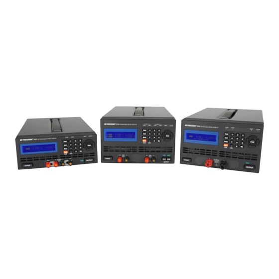
- Page 1 Model: 9171B, 9172B, 9173B, 9174B, 9181B, 9182B, 9183B, 9184B, 9185B Programmable DC Power Supplies USER MANUAL...
- Page 3 Safety Summary The following safety precautions apply to both operating and maintenance personnel and must be observed during all phases of operation, service, and repair of this instrument. Before applying power, follow the installation instructions and become familiar with the operating instructions for this instrument. If this device is damaged or something is missing, contact the place of purchase immediately.
- Page 4 KEEP AWAY FROM LIVE CIRCUITS Instrument covers must not be removed by operating personnel. Component replacement and internal adjustments must be made by qualified maintenance personnel. Disconnect the power cord before removing the instrument covers and replacing components. Under certain conditions, even with the power cable removed, dangerous voltages may exist.
- Page 5 A CAUTION statement calls attention to an operating procedure, practice, or condition, which, if not followed correctly, could result in damage to or destruction of part or all of the product. WARNING: Do not alter the ground connection. Without the protective ground connection, all accessible conductive parts (including control knobs) can render an electric shock.
- Page 6 Compliance Statements Disposal of Old Electrical & Electronic Equipment (Applicable in the European Union and other European countries with separate collection systems) This product is subject to Directive 2002/96/EC of the European Parliament and the Council of the European Union on waste electrical and electronic equipment (WEEE) , and in jurisdictions...
- Page 7 CE Declaration of Conformity The power supplies models 9171B, 9172B, 9173B, 9174B, 9181B, 9182B, 9183B, 9184B, 9185B meet the requirements of 2006/95/EC Low Voltage Directive and 2004/108/EC Electromagnet Compatibility Directive with the following standards. Low Voltage Directive EN61010-1: 2001 Safety requirements for electrical equipment for measurement, control, and laboratory use.
- Page 8 Safety Symbols Refer to the user manual for warning information to avoid hazard or personal injury and prevent damage to instrument. Chassis (earth ground) symbol. On (Power). This is the In position of the power switch when instrument is ON. Off (Power).
-
Page 9: Table Of Contents
Table of Contents General Information ............13 1.1 Product Overview .............. 13 1.2 Package Contents ............... 14 1.3 Front Panel Overview............15 Front Panel Description ............... 17 1.4 Rear Panel Overview ............18 Rear Panel Description ..............20 1.5 Optional Accessories ............21 Interface Card Options .............. - Page 10 3.1 Menu Options ..............41 How to Access the Menu ............. 42 3.2 Remote Interface Setup ............. 45 USB Interface (virtual COM) ............45 GPIB Interface ................47 Ethernet (LAN) Interface ............. 47 RS-232 and RS-485 Interface (Optional) ........48 3.3 Adjusting LCD Display, Key Lock, Key Sound ......
- Page 11 3.10 Save/Recall Output Settings ..........81 3.11 Sequence Program Mode ..........84 3.12 External Analog Control ............. 85 3.13 Digital I/O ................90 INPUT ..................92 OUTPUT ..................93 3.14 Display Errors ..............94 3.15 Connecting in Series and Parallel ........95 Remote Operation ..............
- Page 12 Voltage Calibration ..............178 External Analog Input Calibration..........180 Index ................... 185 SERVICE INFORMATION ............186 LIMITED THREE-YEAR WARRANTY ........187...
-
Page 13: General Information
1 General Information 1.1 Product Overview The 917xB and 918xB series are high-performance dual range linear DC power supplies that provide clean and reliable power with high resolution and accuracy. All models are programmable via standard USB interface or optional RS232, GPIB and LAN interface. Interface cards and I/O cards come in a modular form factor. -
Page 14: Package Contents
1.2 Package Contents Please inspect the instrument mechanically and electrically upon receiving it. Unpack all items from the shipping carton, and check for any obvious signs of physical damage that may have occurred during transportation. Report any damage to the shipping agent immediately. -
Page 15: Front Panel Overview
1.3 Front Panel Overview 11 8 Figure 1 - Front Panel for 9171B/9172B/9181B 7 11 8 Figure 2 - Front Panel for 9173B/9174B... - Page 16 7 11 8 Figure 3 - Front Panel for 9182B/9183B 7 11 8 Figure 4 - Front Panel for 9184B/9185B...
-
Page 17: Front Panel Description
Front Panel Description Power ON/OFF button LCD display Esc / CLR button Menu button ISET button VSET button Decimal/LCL(Local) button Numeric keypad RCL (Recall) button OVP indicator OCP indicator RMT (Remote mode) indicator LOCK (Key lock) indicator Enter button Up, Down arrow keys Left, Right arrow keys Output button (Dual channel models have CH1 and CH2 output buttons) -
Page 18: Rear Panel Overview
1.4 Rear Panel Overview Figure 5- Rear View for 9171B/9172B/9181B... - Page 19 Figure 6- Rear View for 9173B/9174B Figure 7- Rear View for 9182B/9183B...
-
Page 20: Rear Panel Description
Figure 8- Rear View for 9184B/9185B Rear Panel Description S1 interface slot (shown with optional LAN/GPIB interface card) S2 interface slot (shown with optional DIO/Analog interface card) USB interface Temperature controlled cooling fan(s) AC input fuse box Line input receptacle Rear panel outputs (++/--) and sense (+S/-S) terminals Shorting pins Line voltage selection switch (bottom of power supply) See... -
Page 21: Optional Accessories
Rack mount Options Rackmount kits are available for all 9 models. Refer to the following to determine your power supply rack mount size. 2U size: Models 9171B, 9172B, 9181B 3U size: Models 9173B, 9174B, 9182B, 9183B, 9184B, 9185B Model Description... -
Page 22: Display Overview
1.6 Display Overview The main displays for single and dual channel models are shown below. 5 . 000 V1 . 000 A Figure 9- Main Display 5 . 000 V1 . 000 A CH1CV 5 . 000 V1 . 000 A CH2CV Figure 10- Dual Channel Main Display Display Description... -
Page 23: Installing Optional Interface Cards
Selected channel indicators 1.7 Installing Optional Interface Cards Five optional interface cards are available and can be installed in either the S1 or S2 slots. They are: Option 1: GPIB/LAN Card Adds GPIB and LAN interface Option2: DIO/Analog Card (Single channel) Adds digital I/O and External Analog Control Option 3: DIO/Analog Card (Dual channel) Adds dual channel digital I/O and External Analog Control... - Page 24 2. Make note of the metal notches that indicate where the card should slide into. Inside the slot, there are two rails (left and right side) where the card should slide smoothly into. The very back of the slot is a 48-pin female connector that should connect with the 48-pins on the back of the interface card.
-
Page 25: Removing Interface Cards
4. Place the two screws to tighten and secure the installed card. 5. Connect the power cord and turn on the power supply. The newly installed card will be detected during boot up, indicated next to S1: or S2: (depending on which slot the card is installed into). -
Page 26: Rackmount Installation
19-inch rack fitting. Models 9171B, 9172B, 9181B: Follow instructions for 2U rackmount installation. Models 9173B, 9174B, 9182B, 9183B, 9184B, 9185B: Follow... - Page 27 Step 1: Remove the parts 2 3 4 Step 3 Step 1 Step 3: Fas ten the parts Step 2 Step 4 Step 4: Fas ten the parts Step 2: Remove the parts Figure 11- 2U Single Supply Rackmount Installation...
- Page 28 Step 1: Remove the parts Step 2: Fasten the parts Step 1 Step 2 Step 3 Step 4 Step 3: Remove the parts Step 5 Step 4: Fasten the parts Step 5: Remove the parts Step 6 Step 6: Step 7 Fasten the parts Step 7: Fasten the parts...
- Page 29 Step 1: Rem ove th e parts Step 3 Step 1 Step 3: Fas ten the p arts Step 4 Step 2 Step 4: Fas ten th e parts Step 2: Rem ove th e parts Figure 13- 3U Single Supply Rackmount Installation...
- Page 30 Step 1: Remove the parts Step 2: Step 1 Fasten the parts Step 2 Step 3 Step 4 Step 3: Remove the parts Step 5 Step 4: Fasten the parts Step 5: Step 6 Remove the parts Step 7 Step 6: Fasten the parts Step 7: Fasten the parts...
-
Page 31: Getting Started
2 Getting Started 2.1 Input Power and Fuse Requirements Input Power The rated AC input power source for powering the supplies must be within: 115V Operation: 103.5V-126.5V 230V Operation: 207V - 253V Frequency: 47 Hz – 63 Hz Before connecting to an AC outlet or external power source, be sure that the power switch is in the OFF position and verify that the AC power cord, including the extension line, is compatible with the rated voltage/current and that there is sufficient circuit capacity for the... -
Page 32: Line Voltage Selection
Table 1- Input Fuse Table Model 115 V AC 230 V AC 9171B 2.5 A 1.25 A 9172B 2.5 A 1.25 A 9173B 9174B 9181B 3.15 A 1.6 A 9182B 2.5 A 9183B 9184B 9185B Note: All fuses listed have the specifications: T250V, slow blow (slow acting), 5 x 20mm. - Page 33 Step 1 - Check and/or Change Fuse Locate the fuse box next to the AC input connector in the rear panel. With a small flat blade screwdriver, insert into the fuse box slit to pull and slide out the fuse box as indicated below. Check and replace fuse (if necessary) for the desired line voltage operation (see Table 1).
-
Page 34: Output Connections
Rear Panel (Bottom View) Rear Feet Line Voltage Switch Front Feet Front Panel WARNING: Do not connect power to the instrument until the line voltage selection is setup correctly. Applying an incorrect line voltage or configuring the line voltage selection improperly may damage the instrument and void all warranty. - Page 35 For 10 A or higher current output Rear Panel Output Front Panel Output +S + + - - - S Remove shorting bars WARNING: DO NOT output 10 A or more with only one pair of (+) and (-) terminals. Both (+) and (-) terminals must all be connected for applications requiring more than 10 A output.
-
Page 36: Preliminary Check
WARNING: Before connecting wires to the front or rear panel output terminals, turn OFF the power supply to avoid damage to the instrument and the device under test (DUT). For safety, load wires must have a wire gauge size large enough to prevent overheating when the power supply operates at maximum short circuit output current. - Page 37 SRAM TEST ....MAIN TEST ....OK CHECKING FOR EEPROM DATA CHECKING FOR OPTION CARD .
-
Page 38: Output Check
Output Check Voltage Check Follow the steps below to check basic voltage output with no load connected. 1. Turn on the power supply. The display will show the OFF annunciator next to the setting voltage on the left side of the display. - Page 39 Current Check Follow the steps below to check basic current output of the power supply. 1. Turn on the power supply. The display will show the OFF annunciator next to the setting voltage on the left side of the display. 2.
-
Page 40: Check Model And Firmware Version
7. Press POWER to turn off the power supply and remove the short on the output terminals. Check Model and Firmware Version The model and firmware version can be verified from one of the boot up screens, or from using the *IDN? query remote command, described in “4.2 Remote Commands”. -
Page 41: Front Panel Operation
3 Front Panel Operation 3.1 Menu Options All settings and parameters can be configured from the built-in menu system of the power supply. To access the menu, press Menu The menu system is divided into 8 categories and organized as follows: 1. -
Page 42: How To Access The Menu
Low Current Mode (ON,OFF)** 3. PROTECTION 1. OVP SETTING OVP (ON,OFF) SET (0 – Max. Voltage) 2. OCP SETTING OCP (ON,OFF) SET (0 – Max. Current) 4. MEMORY SETTING(0-9) 5. PROGRAM MODE 6. TIMER FUNCTION ... - Page 43 1. From the front panel, press Menu to enter the main menu and the below screen will display. The on the bottom right indicates that there are more categories below that can be displayed. 1 . SYSTEM SETTING 2 . OUTPUT SETTING 3 .
- Page 44 keys to select the setting you want to change. Below is an example of the Remote settings being selected. Note the underline below the first character of the setting “USB”. REMOTE GPIB ADDR KEY LOCK 5. Settings have selectable options that are not numeric (i.e. REMOTE settings shown above).
-
Page 45: Remote Interface Setup
3.2 Remote Interface Setup The standard remote interface available on all models in the series is the USB (virtual COM) interface. Other optional supported interfaces such as GPIB, Ethernet (LAN), RS-232, and RS-485are available, but dependent on the interface card(s) installed on the instrument. - Page 46 2. Install the USB driver. Visit www.bkprecision.com download the driver. Run the setup executable after unzipping the downloaded file. Note: Do this before connecting the USB cable from the power supply to the PC. 3. Once the installation is successful, connect the USB cable between the power supply and the PC.
-
Page 47: Gpib Interface
GPIB Interface GPIB interface is available when the LAN/GPIB card is installed in the “S1” or “S2” slots in the rear panel. To setup the power supply for GPIB interface, follow the steps below: Menu 1. Press , then to enter SYSTEM SETTING. Select until “GPIB”... -
Page 48: And Rs-485 Interface (Optional)
3. If STATIC is selected, then select IP ADDRESS and use the numerical keypad to enter the static IP. After entering each group of 3 digits, press to go to the next group. The Enter cursor will automatically move to the next group. Do this until all 12 digits are entered. - Page 49 BAUDRATE: 57600 PARITY: NONE DATA BITS: 8 STOP BIT: 1 FLOW CONTROL: NONE RS-485 Interface Multiple power supplies (up to 31) can be connected together in series and be controlled via USB (virtual COM) interface. Here is an illustration of how the setup will look like: Figure 15- RS-485 Setup to Control Multiple Supplies (USB) To setup and configure the power supplies, follow these steps: Requirements:...
- Page 50 Note: The cables are used to link the power supplies together. It is recommended to keep the cables as short as possible between each unit. Communicate via USB 1. Take one Ethernet CAT5 cable and connect one end to labeled “OUT” on the RS485 interface card of the first power supply (the one that will be connected to the PC via USB cable).
- Page 51 7. With the connections setup properly, on the first power Menu supply, press , then to enter SYSTEM SETTING. Select REMOTE and verify that “USB” is selected. Press Enter to save changes. 8. Press once to go back to the main menu and press to enter CHAIN SETTING.
-
Page 52: Adjusting Lcd Display, Key Lock, Key Sound
3.3 Adjusting LCD Display, Key Lock, Key Sound LCD Backlight Timer The LCD backlight has a timer that can be set to dim its brightness within a set time from when the instrument is idle. To set this: Menu 1. Press , then to enter SYSTEM SETTING. -
Page 53: Disabling Key Sound
Options Description Default Lock keypad Enter 2. Press to save changes. Press twice to exit the menu. 3. If ON is selected, all keys from the front panel, except , will be locked. The Lock LED indicator will be lit. 4. -
Page 54: Restore To Factory Default
3.4 Restore to Factory Default All instrument settings can be reset back to their factory default values by doing the following: WARNING: Restoring the instrument to factory default will change all current instrument settings and parameters back to their default values. Menu 1. - Page 55 3. To cancel this action, press with NO marked by the Enter cursor. To confirm resetting the instrument to factory default, press to select YES and press Enter 4. After approximately 5 seconds, the instrument will automatically jump back to the normal display. All settings are now set back to their factory default values.
-
Page 56: Configure Voltage And Current Output
3.5 Configure Voltage and Current Output Voltage and Current Limit Settings The power supply has software voltage and current limit protection settings that can be configured to limit the settable range for output from front panel or remote operation. Follow the steps in this section to adjust these settings. - Page 57 VOLT LIMIT MAX = _20.400 V VOLT LIMIT MIN CH2 VOLT LIMIT MAX = _20.400 V CH2 VOLT LIMIT MIN = _ 0.000 V Current Limit Set Menu 1. Press , then to enter OUTPUT SETTING. Press to select CURR LIMIT SETTING. 2.
-
Page 58: Configure Voltage And Current Output
CURR LIMIT MAX = _10.200 A CURR LIMIT MIN= 0.000 A CURR LIMIT MAX = _10.200 A CURR LIMIT MIN = _ 0.000 A Configure Voltage and Current Output Voltage and current can be set and output from the front panel and the rear panel terminals. - Page 59 SET = 5.000 V 5 . 000 V 1 . 000 A For Dual Channel models: SET = 5.000 V 5 . 000 V1 . 000 A CH1 OFF 5 . 000 V 1 . 000 A CH2 OFF 3. Models 9184B and 9185B do not have auto ranging available.
- Page 60 100 . 00 V 2 . 000 A VOLT RANGE = LOW ( : H / : L ) Note: The voltage setting range is dependent on the unit’s maximum voltage output specification as well as the voltage limits set from the system menu. Verify VOLT LIMIT MAX and VOLT LIMIT MIN settings if you are unable to set a voltage within the specifications of the power supply.
- Page 61 For Dual Channel models: SET = 2.000 A 5 . 000 V 2 . 000 A CH1 OFF 5 . 000 V 2 . 000 A CH2 OFF 3. Models 9184B and 9185B do not have auto ranging available. The range must be selected manually and can be set as HIGH or LOW range.
- Page 62 Enable/Disable Output WARNING: Before connecting wires to the front or rear panel output terminals, output should remain OFF to avoid shocks and damage to the device under test (DUT), especially when setting the supply for high voltage output. For safety, load wires must have a wire gauge size large enough to prevent overheating when the power supply operates at maximum short circuit output current.
- Page 63 Controlling Voltage/Current Output with Keys When the output is ON (enabled), the voltage (CV mode) or current (CC mode) output can be controlled incrementally by key presses. To do this, press and a cursor will appear, highlighting the last digit of the measured voltage or current display. Use to change and select the digit you want to change, and press to increase or decrease that digit.
-
Page 64: Slew Rate Configuration
LIMIT MAX and VOLT LIMIT MIN settings if you are unable to set a voltage within the specifications of the power supply. Slew Rate Configuration Voltage and current slew rate of the output can be configured by doing the following: Menu 1. - Page 65 Table 4- Voltage and Current Slew Rate Ranges Model V Slew Rate (V/ms) I Slew Rate (A/ms) 9171B 0.001 – 2.500 0.001 – 1.250 9172B 0.001 – 7.000 0.001 – 0.300 9173B 0.001 –...
-
Page 66: Output Timer Function
9185B 0.001 – 15.00 0.001 – 0.0125 Output Timer Function The power supply has a built-in output timer function that can be enabled to allow setting a time in which output is remained ON. Follow the steps below to setup this function: Menu 1. - Page 67 TIMER = 000 : 00 : 00 Sec 10 . 000 V1 . 000 A For Dual Channel models: TIMER = 000 : 00 : 00 Sec 10 . 000 V1 . 000 A CH1OFF 10 . 000 V1 . 000 A CH2OFF 7.
-
Page 68: Measurement Average Setting
Measurement Average Setting The averaging measurements used to display a reading can be adjusted by following the steps below: Menu 1. Press , then to enter OUTPUT SETTING. Press to select MEASURE AVERAGE. The following will display: AVERAGE TIME = _ 2 2. -
Page 69: Series/Parallel Tracking Mode
Note: When multiple output control is setup, there will be a maximum of 3 ms delay between channel 1 and channel 2 when both channels change output from OFF (disable) state to ON (enable) state. Follow the steps below to configure this setting: Menu 1. -
Page 70: Remote Sense
1 . 000 A CH2OFF 3.7 Remote Sense Single channel models 9171B, 9172B, 9181B, 9182B, and 9183B have both front and rear panel remote sense terminals. Dual channel models 9173B and 9174B, and high voltage single channel models 9184B and 9185B have rear panel remote sense terminals only. - Page 71 +S + + - - - S Front Panel Shorting Bar Rear Panel Shorting Bar Figure 16-Local Sense with Shorting Bar For front panel, +S and + terminals are shorted together, and –S and – terminals are shorted together with shorting bars. For rear panel, +S and + (next to +S) are shorted together, and –S and –...
- Page 72 Figure 17- Front Panel Remote Sense Setup To use remote sense from the rear panel, both front panel (if available) and rear panel shorting bars must also be removed. The rear +S and –S ports are connected directly to the DUT, like Figure 18 below: Figure 18- Rear Panel Remote Sense Setup WARNING:...
- Page 73 DO NOT CONNECT LIKE BELOW: For operating with output current higher than 10 A, the connection is the same as Figure 18 above, with the addition of connecting the second pair of (+) and (-) terminals in the rear panel, like below:...
- Page 74 Rear Panel Output Rear Panel Output Remove Shorting bars +S + + - - - S +S + + - - - S Front Panel Output Remove shorting bars Figure 19- Remote Sense Setup for 10A or Higher Current Output Operation WARNING: DO NOT output 10A or more with only one pair of (+) and (-) terminals in the rear panel.
-
Page 75: Led And Low Current Test Modes
3.8 LED and Low Current Test Modes LED Mode All of these power supplies have LED mode, which enables them to function specifically for LED test applications. When this mode is ON (enabled), the power supply can operate in such a way as to minimize or almost eliminate the inrush current drawn by the LED load, which normally exists when the output switches from an OFF state to an ON state. - Page 76 Figure 20- LED Testing Example The 9184B supply output is initially OFF (disabled). The LED light bar is rated for 170 V. A 10 Ω resistor is placed in series with the LED light bar. The power supply current setting (ISET) is 20 mA. Using an oscilloscope to probe between the resistor to measure current, the power supply’s output is then turned ON.
-
Page 77: Low Current Mode
With LED mode ON (enabled), the power supply can minimize or eliminate any inrush current from turning the output ON, which in turn will minimize damage or life of the LEDs under test. Note: For LED mode to function correctly, the output must be turned OFF when connecting between the power supply and the LEDs under test. - Page 78 2. Press to select ON, then press to confirm the Enter changes. Press twice to exit the menu. LED MODE = OFF Low Current MODE = ON Consider the following example screenshots measuring a voltage chance from 0 V to 60 V with a load of 100 mA connected to the output.
-
Page 79: Output Protection
3.9 Output Protection Configure OVP Overvoltage protection (OVP) is available to limit the voltage output and to protect a connected DUT from an overvoltage condition. When the power supply trips the OVP, a short beep will sound and the OVP (OVP1/OVP2 for dual channel models) LED indicator on the front panel will be lit. -
Page 80: Configure Ocp
2. Press to select ON. Press Enter to confirm the changes, and use the numeric keypad to set the voltage limit for the protection to trip. Press again to save changes. When Enter the power supply voltage output reaches this limit, the OVP will trip. -
Page 81: Save/Recall Output Settings
For Dual Channel models: CH1 OCP = ON SET = 10.000 A CH2 OCP = OFF SET = 10.000 A Enter 2. Press to select ON. Press to confirm the changes, and use the numeric keypad to set the current limit for the protection to trip. - Page 82 Save Output Settings Follow these steps to save settings: Menu 1. Press , then to enter MEMORY SETTING. The following screen will be displayed: MEM = 0 0.000 V 0.000 A For Dual Channel models: MEM = 0 0.000 V 0.000 A 0.000 V 0.000 A...
- Page 83 5. For dual channel models, repeat step 3 twice, once for CH1 and for CH2. Each memory location will store both channels’ voltage and current settings. Recall Output Settings To recall a saved setting: 1. Press and the screen will display as follows: RECALL = 0.000 V 0.000 A...
-
Page 84: Sequence Program Mode
Menu 1. Press , then to enter SYSTEM SETTING. Select POWER ON STATE. Press to change it to LAST for setting the power on state to last known configuration. Select OFF to turn it off. 2. Press to confirm the change. Enter 3.11 Sequence Program Mode Up to 10 (1 –... -
Page 85: External Analog Control
Menu 1. Press , then to enter PROGRAM MODE. The following screen will be displayed: PROGRAM NUMBER = 0 PROGRAM OFF 2. Use the keypad to select the program number where the sequence is stored. Valid number is 1 – 10. Press Enter confirm the program. - Page 86 Note: The external control circuit uses a 12-bit D/A converter, thus resolution for voltage and current is limited to 10 mV and 10 mA respectively. WARNING: The terminals for external analog control of voltage and current have no input protection. Therefore take caution when connecting to a DC source or a resistance.
- Page 87 will output 0 V. Applying 10 V input for V will output 35 V or 70 V depending on the range. Likewise, 10 V for I will set current to 3A or 1.5 A depending on the range. See the setup below: 0 –...
- Page 88 and 0 kΩ will set the minimum voltage/current output, which is 0 V/0 A (The scale factor is linear to the full scale voltage/current output). See the setup below: 0 – 5 kΩ 0 – 5 kΩ Dual channel DIO/Analog Card + - + - + - + - + - + -...
- Page 89 Menu 1. Press , then to enter SYSTEM SETTING. 2. Go down to EXTERN CONTROL (this option is only available with DIO/Analog Card installed) and press to select between OFF, VOLT, or RES. Select VOLT for external voltage control or RES for external resistance control.
-
Page 90: Digital I/O
0.00 V 0.00 A 0.00 V 0.00 A 5. Press OUTPUT to turn the output ON (enabled), and output voltage and current will change as your external DC voltage sources or resistances change. Note: When external analog control is enabled, all front panel keys are locked except for for dual Menu... - Page 91 + - + - + - + - Dual Channel DIO/Analog Card Single Channel DIO/Analog Card Figure 25- Digital I/O Interface Below are the pin assignments for each of the 9 pins. Table 5- Digital I/O Pin Assignment Pin# Type Binary Bit # Decimal Representation...
-
Page 92: Input
WARNING: Do not input more than 5 V to any of the digital I/O pins. Doing so may damage the instrument and void its warranty. INPUT Digital input for representing logic high (1) is 5 V, and for logic low (0) is 0 V. -
Page 93: Output
use the GPIO? query command. It will return the decimal representation of the 8-bits binary that represents all the pins. The pins with bit value “1” have 5 V at the input, and “0” for 0 V at input. For example, suppose all pins are set as INPUT pins, but only pin 2 and 1 have a 5 V logic high (1) signal, then only these two pins return “1”... -
Page 94: Display Errors
have the value “1”, which represents OUTPUT. Digital output for representing logic high (1) is 5 V, and for logic low (0) is 0 V. To set an output pin’s logic level, use the GPIO remote command. Again, all pins (except pin 5) are represented as 8-bits binary, according to Table 5 above. -
Page 95: Connecting In Series And Parallel
Only connect multiples units in series or parallel of the same model. Do not mix models together. For example, you can connect two 9171B together, but not 9171B and 9172B together. Do not connect more than 2 units of models 9174B when series/parallel tracking is used. - Page 96 When increasing the total output current by connecting multiple units in parallel, be sure that the connecting wires have enough thickness to handle the amount of current. Otherwise, they may overheat and/or drop voltage levels significantly.
-
Page 97: Remote Operation
4 Remote Operation 4.1 Interface Connection USB (Virtual COM) & RS-232 All models have a standard USB interface (virtual COM) that can be used for remote communication. Optionally, an RS232 interface card is available for remote control via RS-232 interface. Both USB (virtual COM) and RS-232 have the same serial settings listed below: BAUDRATE: 57600... -
Page 98: Gpib
Table 6- RS-232 Pin Out Description Transmit Data Receive Data A straight pin-to-pin DB9female to DB9male serial cable is required for using RS-232 interface. Do not use a null modem or crossover DB9 serial cable. GPIB GPIB option is available when the supply is installed with the optional LAN/GPIB interface card. -
Page 99: Ethernet (Lan)
Ethernet (LAN) Ethernet (LAN) option is available when the supply is installed with the optional LAN/GPIB interface card. There are three ways to control the power supply via LAN interface: Web server, Telnet connection, Socket connection. Web Server There is an embedded web server GUI that can access the power supply via LAN interface using a java enabled web browser. - Page 100 91XXB 4. A password is required to login and access any of the menu items on the page. DEFAULT ADMIN PASSWORD: 123456 Menu Items This table describes each of the menu items available on the left frame of the web browser GUI. Table 7- Web Browser Menu Description Home Provides general information of the power supply:...
- Page 101 Vset, Iset, Output state, Output On Timer. Figure 28 Configuration Page Screenshot Figure 29 Web Control Page Screenshot...
- Page 102 Telnet Connection The power supply can be connected via Ethernet (LAN) interface using Telnet client with the following port: Telnet Port: 5024 Windows XP Users 1. Open a command prompt window, which can be found by going to Start > All Programs > Accessories > Command Prompt.
- Page 103 Windows Vista/7 Users By default, Telnet client is not installed on the system. There are two ways to install it manually: 1. Open command prompt: a. Select Windows Start > All Programs > Accessories > Command Prompt b. Select Windows Start and type in cmd in the Search programs and files box and click on cmd.exe in the search list.
-
Page 104: Remote Commands
2. Alternatively, go to Control Panel, select Programs, and select Turn Windows features on or off. Wait until the list gets populated. Then, Click the box next to Telnet Client. When finished, follow steps 1a or 1b to open Command Prompt and follow the same steps 2 and 3 from “Windows XP users”... -
Page 105: Parameter Definitions
Parameter Definitions Unless otherwise noted, the following table of parameter definitions applies to all supported remote commands. Commands that have [ ] around them are optional. For example, [SOURce] is not required for the SOURCE subsystem. Table 8- Parameter Definitions Parameter Description <Boolean>... - Page 106 and/or will not have a response. All commands listed in this section do not have the termination character shown, but it is required for successful communication with the power supply.All returned strings after a query command will terminate with both <CR> and <LF> characters. For example, sending VOLT?command may return: 1.234<CR><LF>...
- Page 107 *SAV Description: Saves power supply settings into a memory location Syntax: *SAV<SP><location> <location> - Memory location number to save settings into. 0 – 9 are valid numbers. Example: *SAV 2 Saves instrument settings into memory location 2. *RCL Description: Recalls power supply settings Syntax: *RCL<SP><location>...
- Page 108 :VSET2 :ISET :ISET2 :SAV Output Subsystem OUTput :ALL :LIMit :VOLTage :VOLT2 :CURRent :CURR2 :MAX :VOLTage :VOLT2 :CURRent :CURR2 :MIN :VOLTage :VOLT2 :CURRent :CURR2 :VOLTage :VOLT2 :CURRent :CURR2 :STATE? :PROTection :CLEar Channel 2 Output Subsystem (dual channel models only) OUT2 :STATe? Program Subsystem PROGram :CLEar...
- Page 109 :CURR2 :ONTime :VOLTage :VOLT2 :TOTAl Protection Subsystem PROTection :CLEar :OCP :LEVel :OCP2 :LEVel :OVP :LEVel :OVP2 :LEVel Source Subsystem [SOURce] :CURRent :PROTection :LEVel :CURR2 :PROTection :LEVel :VOLTage :PROTection :LEVel :RANGe :VOLT2 :PROtection :LEVel System Subsystem SYStem :AVErage :BEEP :ERRor? :EXTernal :LEVel :GPIB :ADDRess...
- Page 110 :LOCK :LCD :LED :LOW :CURR :OUTput :MODE :RECall :DEFault :REMote :SERies? :TRACK Timer Subsystem TIMER :HOUR :MINute :SECond GPIOSubsystem Note: The optional Analog/DIO interface card must be installed to use all GPIO commands. Table 9- Digital I/O Representation Pin# Type Binary Bit # Decimal Representation...
- Page 111 GPIO Description: Configures digital I/Opins level to high (1) 5V or low (0) 0V for output pins. Nothing happens if the pin is an input. Syntax: GPIO<SP><decimal> <decimal> - Decimal representation of the binary value representing the GPIO pins. 0 – 255 are valid. Example: GPIO 46 Sets pins 7, 4, 3, and 2 to logic high(1) 5 V output if...
- Page 112 GPIO:DIRection? Description: Queries the digital I/O pins as outputs or inputs.Binary value of 1 is output and 0 is input. Query: GPIO:DIR? Return String: Pins 9, 8, 7, 4, 3, and 1 are outputs and the rest are inputs. (See “Table 9” to convert the binary representation).
- Page 113 Note: For dual channel models only. Description: Queries the measured voltage value of channel 2 Query: MEAS:VOLT2? Return String: 1.234 The measured current is 1.234 V. Format: <NRf> Memory Subsystem MEMory Description: Selects the memory location/Returns the selected memory location. Syntax: MEMory<SP><decimal>...
- Page 114 Description: Configures/Queries the second channel voltage value to store at the selected memory location (use “MEM” command to select memory location first) Syntax: MEMory:VSET2<SP><decimal> <decimal> - Voltage value. 0 – max. rated voltage value are valid. Example: MEM:VSET2 4.132 Sets 4.132 V as voltage for the selected memory location.
- Page 115 location. Query: MEM:ISET2? Return String: 2.159 Current is currently set to 2.159 A in the selected memory location for channel 2. Format: <NRf> MEMory:SAV Description: Saves the configured voltage and current (using MEM:VSET and MEM:ISET commands) values into the selected memory location (using MEM command).
- Page 116 OUTput:LIMit:VOLTage Description: Configures/Queries the voltage maximum limit. For dual channel models, this will configure voltage limit for channel 1. Syntax: OUTput:LIMit:VOLTage<SP><voltage> OUTput:LIMit:VOLTage? <voltage> - Voltage value. 0 – max. rated voltage value are valid. Example: OUT:LIM:VOLT 70.123 Sets the voltage maximum limit to 70.123 V. Query: OUT:LIM:VOLT? Return String:...
- Page 117 Query: OUT:LIM:CURR? Return String: 3.456 Format: <NRf> OUTput:LIMit:CURR2 Note: For dual channel models only. Description: Configures/Queries the current maximum limit for channel 2. Syntax: OUTput:LIMit:CURR2<SP><current> OUTput:LIMit:CURR2? <current> - Current value. 0 – max. rated current value are valid. Example: OUT:LIM:CURR 3.456 Sets the current maximum limit to 3.456 A.
- Page 118 OUTput:MIN:VOLTage? <voltage> - Voltage value. Less than max. voltage set limit Example: OUT:MIN:VOLT 0 Sets the voltage minimum limit to 0 V. Query: OUT:MIN:VOLT? Return String: Format: <NRf> OUTput:MIN:VOLT2 Note: For dual channel models only. Description: Configures/Queries the voltage minimum limit for channel 2.
- Page 119 Syntax: OUTput:MIN:CURR2<SP><current> OUTput:MIN:CURR2? <current> - Current value. Less than max. current limit value are valid. Example: OUT:MIN:CURR2 0 Sets the current minimum limit to 0 A. Query: OUT:MIN:CURR2? Return String: Format: <NRf> OUTput:SR:VOLTage Description: Configures/Queries the voltage slew rate in unit of V/ms.
- Page 120 OUTput:SR:CURRent Description: Configures/Queries the current slew rate in unit of A/ms. For dual channel models, this will configure the slew rate for channel 1. Syntax: OUTput:SR:CURRent<SP><current> OUTput:SR:CURRent? <current> - Current value. 0 – max. current slew rate value. See “Slew Rate Configuration” in section 3.5. Example: OUT:SR:CURR 1.000 Sets the current slew rate to 1.000 A/ms.
- Page 121 The commands in this subsystem are for dual channel models only. OUT2 Description: Configure/Query the state of the output for channel 2. Syntax: OUT2<SP><Boolean> OUT2? Example: OUT2 1 OUT2 ON Enables the output for channel 2. Query: OUT2? Return String: Format: ON or OFF OUT2:STATe?
- Page 122 Format: <NR1> PROGram:CLEar Description: Clears all programmed sequences stored in the selected program location (Select using PROG command) Syntax: PROGram:CLEar Example: PROG:CLE Clears the programmed sequence at the selected program location. PROGram:CLEar:ALL Description: Clears all programmed sequences stored in all 10 program locations.
- Page 123 selected programmed sequence. Syntax: PROGram:REPeat<SP><number> PROGram:REPeat? <number> - 1 – 50000 (max.) Example: PROG:REP 10 Runs the set of sequences in the selected program location 10 times. Query: PROG:REP? Return String: Currently set to repeat the sequence 300 times. Format: <NR1>...
- Page 124 Query: PROG:STEP? Return String: Currently selecting step 30 in the sequence for setup. Format: <number> PROGram:STEP:CURRent Description: Configures/Queries the current setting for the selected step (use PROGram:STEP command to select step). For dual channel models, this will be for channel 1. Syntax: PROGram:STEP:CURRent<SP><current>...
- Page 125 PROGram:STEP:ONTime Description: Configures/Queries the step timing (the length of period to hold the settings) of the selected sequence. Unit is in seconds. Syntax: PROGram:STEP:ONTime<SP><seconds> PROGram:STEP:ONTime? <seconds> - 0.010 – 2000 (max.) Example: PROG:STEP:ONT 0.050 Set the selected step time to 0.050 seconds (50 ms). Query: PROG:STEP:ONT? Return String:...
- Page 126 Format: <NRf> PROGram:TOTAl Description: Configures/Queries the total number of step numbers for the program sequence. Syntax: PROGram:TOTAl<SP><number> PROGram:TOTAl? <number> - 2 -150 (max.) Example: PROG:TOTA 100 Setup a program sequence with 100 steps. Query: PROG:TOTA? Return String: Currently the sequence will have 30 steps for setup. Format: <NR1>...
- Page 127 PROTection:OCP:LEVel Description: Configures/Queries the current level for OCP. Syntax: PROTection:OCP:LEVel<SP><current> PROTection:OCP:LEVel? <current> - 0 – max. rated current. Example: PROT:OCP:LEV 3.000 Set 3.000 A as the OCP current level. Query: PROT:OCP:LEV? Return String: 3.000 Format: <NRf> PROTection:OCP2 Note: For dual channel models only. Description: Configures/Queries the state of OCP channel 2.
- Page 128 PROTection:OVP Description: Configure/Query the state of OVP (over voltage protection). Syntax: PROTection:OVP<SP><Boolean> PROT:OVP? Example: PROT 1 PROT ON Enables OVP Query: PROT:OVP? Return String: Currently OVP is disabled. Format: ON or OFF PROTection:OVP:LEVel Description: Configures/Queries the voltage level for OVP. Syntax: PROTection:OVP:LEVel<SP><voltage>...
- Page 129 PROTection:OVP2:LEVel Note: For dual channel models only. Description: Configures/Queries the voltage level for OVP for channel 2. Syntax: PROTection:OVP2:LEVel<SP><voltage> PROTection:OVP2:LEVel? <voltage> - 0 – max. rated voltage. Example: PROT:OVP2:LEV 20.000 Set 20.000 V as the OVP voltage level for channel 2. Query: PROT:OVP2:LEV? Return String:...
- Page 130 Description: Configures/Queries the ISET current setting for channel 2. Syntax: [SOURce]:CURR2<SP><current> [SOURce]:CURR2? <current> - 0 – max. rated current. Example: SOUR:CURR21.456 Set current of channel 2 to 1.456 A. Query: SOUR:CURR2? Return String: 1.456 Format: <NRf> [SOURce]:CURR2:PROTection Note: See PROTection:OCP2 command. [SOURce]:CURR2:PROTection:LEVel Note: See PROTection:OCP2:LEVel command.
- Page 131 [SOURce]:VOLTage:RANGe Note: This command is for models 9184B and 9185B only. Description: Configures/Queries the voltage range. Syntax: [SOURce]:VOLTage:RANGe<SP><range> [SOURce]:VOLTage:RANGe? <range> - 0 or 1 / LOW or HIGH Example: SOUR:VOLT:RANG LOW SOUR:VOLT:RANG 0 Set the supply to the low voltage range. Query: SOUR:VOLT:RANG? Return String:...
- Page 132 setting. Syntax: [SYStem]:AVErage<SP><number> [SYStem]:AVErage? <number> - 1 – 10 are valid numbers. Example: SYS:AVE2 Set measurement average to 2. Query: SYS:AVE? Return String: Format: <NR1> SYStem:BEEP Description: Configure/Query the state of the key sound. Syntax: SYStem:BEEP<SP><Boolean> SYStem:BEEP? Example: SYS:BEEP 0 SYS:BEEP OFF Disables the key sound.
- Page 133 Command Error Execution Error Query Error Input Range Error SYStem:EXTernal Description: Configure/Query the state/type of the analog external control. Syntax: SYStem:EXTernal<SP><type> SYStem:EXTernal? <type> - 0/OFF, 1/VOLT, 2/RES Example: SYS:EXT 1 SYS:EXT VOLT Set to use voltage source for external analog control Query: SYS:EXT? Return String:...
- Page 134 Example: SYS:GPIB:ADDR 6 Sets the GPIB address to 6. Query: SYS:GPIB:ADDR? Return String: Format: <NR1> SYStem:IP:ADDRess Description: Configure/Query the LAN IP address Syntax: SYStem:IP:ADDRess<SP><ip> SYStem:IP:ADDRess? <ip> - NR1.NR1.NR1.NR1. NR1 can be from 000 – 255. Example: SYS:IP:ADDR 192.168.001.150 Sets the IP address to 192.168.1.150 Query: SYS:IP:ADDR? Return String:...
- Page 135 SYStem:LCD:BL Description: Configures/Queries the LCD backlight state Syntax: SYStem:LCD:BL<SP><state> SYStem:LCD:BL? <state> - 0/ON, 1/OFF1, 2/OFF5, 3/OFF10, 4/OFF30 (For Always ON, ON 1 minutes, ON 5 minutes, ON 10 minutes, ON 30 minutes respectively) Example: SYS:LCD:BL Enables key lock. Query: SYS:KEY? Return String: Format: ON or OFF...
- Page 136 SYStem:OUTput:MODE Note: For dual channel models only. Description: Configures/Queries the state of the output mode. Syntax: SYStem:OUTput:MODE<SP><state> SYStem:OUTput:MODE? <state> - 0/MULTI or 1/SINGLE Example: SYS:OUT:MODE 0 SYS:OUT:MODE MULTI Sets output mode to MULTI. Query: SYS:OUT:MODE? Return String: MULTI Format: SINGLE or MULTI SYStem:RECall:DEFault Description: Resets back to default factory settings.
- Page 137 Description: Queries the serial number of the instrument. Syntax: SYStem:SERies? Query: SYS:SER? Return String: 123D12101 Serial number of the instrument is 123D12101. SYStem:TRACK Note: For dual channel models only. Description: Configures/Queries the state of tracking mode. Syntax: SYStem:TRACK<SP><Boolean> SYStem:TRACK? Example: SYS:TRACK 1 SYS:TRACK ON Enables tracking mode.
- Page 138 <hour> - 0 - 999 Example: TIMER:HOUR 100 Sets the output timer to 100 hours. Query: TIMER:HOUR? Return String: Format: <NR1> TIMER:MINute Description: Configures/Queries the output timer hours. Syntax: TIMER:MINute<SP><hour> TIMER:MINute? <hour> - 0 - 59 Example: TIMER:MIN 40 Sets the output timer to 40 minutes. Query: TIMER:MIN? Return String:...
- Page 139 the SCPI commands described in the previous section. For example, MEASure:CURRent? functions the same as IOUT?. ADDRess Description: Configures/Queries the GPIB address Syntax: ADDRess<SP><address> ADDRess? <address> - GPIB address. 0 – 30 are valid addresses. Example: ADDR 10 Sets the GPIB address to 10. Query: ADDR? Return String:...
- Page 140 Description: Selects the channel to configure. Syntax: CHANnel<SP><channel> CHANnel? <channel> - 1 or 2. Example: CHAN 2 Selects channel 2. Query: CHAN? Return String: Format: <channel> CURRent/CURR2 Note: CURR2 command is for dual channel models only. Description: Configures/Queries the ISET current setting. For dual channel models, use CURR2 command for channel 2.
- Page 141 Query Error Input Range Error IOUT?/IOUT2? Note: IOUT2 command is for dual channel models only. Description: Queries the measured/readback current output value. For dual channel models, use IOUT2 command for channel 2. Syntax: IOUT? IOUT2? Example: IOUT? Return String: 2.156 Output current measured is 2.156 A.
- Page 142 Description: Queries the model number Syntax: MODEL? Example: MODEL? Return String: 9174B Format: <model> OCP/OCP2 Note: OCP2 command is for dual channel models only. Description: Configures/Queries the over current protection state. For dual channel models, use OCP2 command for channel 2. Syntax: OCP<SP><state>...
- Page 143 Format: <NRf> OUT/OUT2 Note: OUT2 command is for dual channel models only. Description: Configures/Queries the output state. For dual channel models, use OUT2 command to configure/query channel 2 output state. Syntax: OUT<SP><state> OUT2<SP><state> OUT? OUT2? <state> - ON or 1 to turn ON - OFF or 0 to turn OFF Example: OUT 1...
- Page 144 Return String: SINGLE Format: <mode> OVP/OVP2 Note: OVP2 command is for dual channel models only. Description: Configures/Queries the over voltage protection state. For dual channel models, use OVP2 command for channel 2. Syntax: OVP<SP><state> OVP2<SP><state> OVP? OVP2? <state> - ON or 1 to turn ON - OFF or 0 to turn OFF Example: OVP2 ON...
- Page 145 Return String: 70.000 OVP is set to 70.000 V Format: <NRf> STATUS? Description: Queries the instrument status Syntax: STATUS? Example: STATUS? Return String: 000000 No OVP, OCP, OTP, and other failure or flagged status. Outputs are off, LCD backlight always ON, and output mode set to MULTI.
- Page 146 1 is ON, 0 is OFF Channel 1 OVP On/Off status 1 is ON, 0 is OFF Channel 2 OVP On/Off status 1 is ON, 0 is OFF Channel 1 OCP On/Off status 1 is ON, 0 is OFF Channel 2 OCP On/Off status 1 is ON, 0 is OFF Channel 1 output On/Off status 1 is ON, 0 is OFF...
- Page 147 Example: TRACK ON Turns ON (enables) tracking mode. Query: TRACK? Return String: Format: <state> VERsion? Description: Queries the firmware version Syntax: VERsion? Example: VERsion? Return String: 1.10 Format: <NRf> VOLTage/VOLT2 Note: VOLT2 command is for dual channel models only. Description: Configures/Queries the VSET voltage setting.
-
Page 148: Sequence Programming
Format: <NRf> VSET/VSET2 Description: This command is the same as VOLTage/VOLT2 command. See VOLTage/VOLT2 for details. Example: VSET? VSET 12.345 Format: <NRf> 4.3 Sequence Programming The power supply has the ability to store custom programmed sequences and run them, as described in “3.11Sequence Program Mode”. - Page 149 commands in order: PROG 1 Choose program number PROG:CLE Clear program 1 data PROG:REP 0 No repeat (repeat one time for “1”) PROG:TOTA 8 Set program 1 to have 8 steps in total PROG:STEP 1 Following 3 settings are for step 1 PROG:STEP:CURR 1 Set output current to 1 ampere PROG:STEP:VOLT 5...
- Page 150 PROG:STEP:CURR 1 PROG:STEP:VOLT 0 PROG:STEP:ONT 0.1 Select next program to run after program PROG:NEXT 0 1 is complete, 0 means Stop PROG:SAV After edit, use Save command to store program 1 in the hardware PROG 1 Select program 1 PROG:RUN ON Use RUN ON command to execute Example 2: To create an output sequence like above, send the following list of...
- Page 151 PROG:STEP:ONT 0.5 PROG:STEP 3 Settings for step 3 PROG:STEP:CURR 2 PROG:STEP:VOLT 20 PROG:STEP:ONT 0.5 PROG:STEP 4 Choose step 4 PROG:STEP:CURR 2 PROG:STEP:VOLT 10 PROG:STEP:ONT 0.5 PROG:STEP 5 Choose step 5 PROG:STEP:CURR 1 PROG:STEP:VOLT 20 PROG:STEP:ONT 0.5 PROG:STEP 6 Choose step 6 PROG:STEP:CURR 2 PROG:STEP:VOLT 5 PROG:STEP:ONT 0.5...
-
Page 152: Multi Unit Programming
To execute example 2 sequence after example 1 sequence, then modify sequence of example 1 with NEXT 2 command. Send the following steps to modify and execute the program to generate a waveform sequence shown above. PROG 1 Select program 1 PROG:NEXT 2 Change the NEXT command from NEXT 0 to NEXT 2... -
Page 153: Remote Commands Via Usb
Figure 30- Multi Unit Programming The following describes the specific commands that may be used to communicate with each connected instrument with this specific setup. Remote Commands via USB The following lists all the available commands to control multiple power supplies with the multi unit programming configuration illustrated in “Figure 30”. - Page 154 CADR CCLS CRST CIDN? CREV CSN? CST? CCLR CADR Note: This command must be used first prior to any other commands to control individually addressed power supplies with RS-485 connection. Description: Selects the address of the power supply to be controlled.
- Page 155 This command functions the same as *IDN?, however this is used in a multi unit programming setup for the selected power supply. Query: CIDN? Return String: B&K PRECISION,9171B,SN#,1.10,0 CREV? Description: Queries the firmware version of the selected power supply. Query:...
- Page 156 to control that unit’s output. CPV/CPV2 CMV?/CMV2? CPC/CPC2 CMC?/CMC2? CDVC?/CDVC2? COUT/COUT2 COUTA COV/COV2 COVP/COVP2 COC/COC2 COCP/COCP2 CMODE?/CMODE2? CPV/CPV2 Description: Configures/Queries the VSET voltage setting of the selected power supply. See VOLTage/VOLT2command for similar syntax.CPV2 is for dual channel models only. Example: CPV 15.698 Sets the selected power supply’s VSET voltage...
- Page 157 Return String: 1.234 V The selected power supply has a measured output voltage of 1.234 V. CPC/CPC2 Description: Configures/Queries the ISET current setting of the selected power supply. See CURRent/CURR2 command for similar syntax.CPC2 is for dual channel models only. Example: CPC 3.123 Sets the selected power supply’s ISET current setting...
- Page 158 Format: <voltage>,<current> COUT/COUT2 Description: Configures/Queries the output state of the selected power supply. See OUT/OUT2 command for similar syntax.COUT2 is for dual channel models only. Example: COUT ON Sets the selected power supply’s output to ON. COUT2? Queries the selected power supply’s second channel output state.
- Page 159 OVP state. COC/COC2 Description: Configures/Queries the over current protection value of the selected power supply. See OISET/OISET2 command for similar syntax. COC2 is for dual channel models only. Example: COC 3.000 Sets the selected power supply’s OCP value to 3.000 COC2? Queries the selected power supply’s second channel OCP value.
- Page 160 Return String: Format: CV or CC Examples Here are a few examples of how to configure/query an instrument connected in the RS-485 chain. Query the IDN information for power supply with address 3 CADR 3 CIDN? Configure ISET current of a dual channel supply with address 10 to 1.234 A.
- Page 161 This set of commands can be used to control all the power supplies connected in the RS-485 chain at once. Note that these commands will not return an “OK” string upon making a configuration. GRST GCLS GCLR GPV/GPV2 GPC/GPC2 GOUT/GOUT2 GOUTA GOV/GOV2 GOVP/GOVP2...
- Page 162 GPV/GPV2 Description: Configures/Queries the VSET voltage setting of all the power supplies connected in the chain. See VOLTage/VOLT2 command for similar syntax. GPV2 is for dual channel models only. Example: GPV 15.698 Sets all the power supplies’ VSET voltage setting to 15.698 V.
- Page 163 Description: Configures/Queries the over voltage protection value of all the power supplies connected in the chain. See OVSET/OVSET2 command for similar syntax. GOV2 is for dual channel models only. Example: GOV 70.000 Sets all the power supplies’ OVP value to 70.000V. GOVP/GOVP2 Description: Configures/Queries the over voltage protection state...
- Page 164 configuration, a response string is returned. If the command was sent successfully to the power supply(s) (except for Synchronous Control Commands), the return string will be “OK”. If otherwise, an error message will occur. See the table below for the list of errors and their descriptions.
-
Page 165: Troubleshooting Guide
5 Troubleshooting Guide Below are some frequently asked questions and answers. Please check if any applies to your power supply before contacting B&K Precision. General Q: I cannot power up the power supply. Check that the power cord is securely connected to the AC input and there is live power from your electrical AC outlet. - Page 166 under test), which causes a drop in voltage. To minimize this drop, use remote sense terminals to compensate and output a more accurate voltage to the DUT. Q: On my dual channel power supply, how do I set a timer output for each channel? The two channels are dependent on the same timer function.
-
Page 167: Remote Control
Remote Control Q: I am trying to send the commands over USB/RS232, but it does not seem to respond. Check that you are sending ASCII strings that are terminated with a CR (carriage return) and LF (linefeed) character. For USB, check that the correct USB drivers are installed and that you are communicating with the right COM port, which can be verified under “Device Manager”... -
Page 168: Specifications
Note: All specifications apply to the unit after a temperature stabilization time of 15 minutes over an ambient temperature range of 23 °C ± 5 °C. Specifications are subject to change without notice. Model 9171B 9172B Output Rating Low Range 0–10V/0 -10A... - Page 169 Model 9181B 9182B Output Rating Low Range 0–18V/0–8A 0–10V/0–20A High Range 0–36V/0–4A 0–20V/0–10A Output Channel Output Power 144W 200W General Maximum Rated Input 230VA 680VA Power 210mmx87mmx414m 210mmx130.5mmx4 Dimension(W*H*D) 15mm Weight 7.7kg 12kg Model 9183B Output Rating Low Range 0–35V/0–6A High Range 0–70V/0–3A Output Channel...
- Page 170 Load Regulation ≤ 0.01%+1mV Voltage ≤ 0.01%+250uA Current Ripple and Noise (20Hz-20MHz) ≤ 0.35mVrms/≤ 3mVpp (9171B,9173B,9181B,9182B) ≤ 0.5mVrms/≤ 5mVpp Normal Mode Voltage (9172B,9174B,9183B) ≤ 1.5 mVrms/≤ 15 mVpp (9184B) ≤ 4.5 mVrms/≤ 45 mVpp (9185B) ≤ 2mA rms Normal Mode Current ≤...
- Page 171 ≤ 0.02%+20 mV(9185B) ≤ 0.1%+1mA Current Settling Time ≤ 30ms ≤ 5ms Measurement Time ≤ 50μs (9171B - 9183B) Transient Response Time ≤ 100μs (9184B, 9185B) ≤ 0.5%+0.1V (9171B – 9183B) OVP Accuracy ≤ 0.5%+1V (9184B, 9185B) ≤ 0.5%+0.1A OCP Accuracy ≤...
- Page 172 VOLTage or VSET command via direct GPIB or USB interface. Models 9171B – 9183B: Less than 50 μs for output to recover to within 15 mV following a change in output current from full load to half load or vice versa.
- Page 173 Average time for output to start to drop after OVP/OCP condition occurs. Digital I/O Analog Control Card Accuracy:±1%. To ensure the most current version of this manual, please download the latest version here: http://www.bkprecision.com/search/9171B For current up-to-date product information, please visit www.bkprecision.com...
-
Page 174: Calibration
7 Calibration Access Calibration Menu Follow the steps below to access the calibration menu. Menu 1. Press , then to enter CALIBRATION. The following screen will be displayed: PLEASE KEYIN PASSWORD : _ 2. Enter the password: 13579 with the numeric keypad. 3. -
Page 175: Current Calibration
The following equipment is required for the calibration procedure: 6 ½ digit precision digital multimeter Shunt for current calibration (Necessary if the maximum output current of the power supply is greater than the maximum current the multimeter is capable of measuring) ... - Page 176 6 ½ Digit DMM Figure 32- Current Calibration with Shunt Follow the steps below to proceed with current calibration: 1. From the calibration menu, press to enter CURRENT CALIBRATION. The following screen will be shown. CURRENT CALIBRATION CH: 1 Set = X . XXXXA Read = XXX IML Set = X .
- Page 177 3. The power supply will output a pre-set current to the DMM. Wait for the DMM reading to settle, then enter it into where it shows IL Set = __.____A on the display. Press to proceed to IML. Enter If current shunt is used for the calibration, divide the DMM readings (in DCV) by the resistance (Rs) of the shunt.
-
Page 178: Voltage Calibration
Voltage Calibration Use the setup diagram shown in Figure 33 below for voltage calibration. Connect the rear output terminals of the power supply to the DMM. 6 ½ Digit DMM Figure 33- Voltage Calibration Setup Follow the steps below to proceed with voltage calibration: 1. - Page 179 2. Select the channel (for dual channel models), then press Enter The calibration process will automatically start. 3. The power supply will output a pre-set voltage to the DMM. Wait for the DMM reading to settle, then enter it into where it shows VL Set = __.____V on the display.
-
Page 180: External Analog Input Calibration
External Analog Input Calibration This calibration option is only available if the optional DIO/Analog Interface Card is installed in the power supply. Follow the steps below to proceed with external analog input calibration. 1. From the calibration menu, press to enter EXT. INPUT CALIB. - Page 181 Calib EXT . Lo Volt = 1 . 000 V Calib EXT . Lo Volt = 9 . 000 V CH 1 EXT . VOLT Res = Start CH 1 EXT . CURR Res = Start CH 2 EXT . VOLT Res = Start CH 2 EXT .
- Page 182 5. To begin calibration with the external resistor, remove the DC source and connect the precision resistor to the control card, as shown in Figure 37(right) below. Figure 37- External Resistance Control Calibration setup (left) Current (right) Voltage 6. The supply will display CH1 EXT. VOLT Res. Press Enter calibrate.
- Page 183 Figure 38- Dual Channel External Analog Voltage Input Calibration Setup 10. (Dual channel) For the external resistor calibration, connect like for channel 1 for current and voltage, and connect like for channel 2 for current and voltage. 11. Once finished, the supply will return to the calibration menu. To exit and go back to the main display, press twice.
- Page 184 Figure 40- Channel 2 Setup for External Analog Resistor Input Calibration...
-
Page 185: Index
Index AC input, 19 OVP, 67 Calibration, 161 Power-On State, 71 CHAIN SETTING, 39 Rackmount, 9 Current Limit, 45 rear output terminals, 22 Digital I/O, 78 Recall, 71 Dual Channel, 50, 56 Remote Commands, 92 Enable/Disable Output, 50 Remote Sense, 58 errors, 82 Resistance, 75 Ethernet (LAN), 35, 89... -
Page 186: Service Information
SERVICE INFORMATION Warranty Service: Please go the support and service section on our website www.bkprecision.com to obtain a RMA #. Return the product in the original packaging with proof of purchase to the address below. Clearly state on the RMA the performance problem and return any leads, probes, connectors and accessories that you are using with the device. -
Page 187: Limited Three-Year Warranty
LIMITED THREE-YEAR WARRANTY B&K Precision Corp. warrants to the original purchaser that its products and the component parts thereof, will be free from defects in workmanship and materials for a period of three year from date of purchase. B&K Precision Corp. will, without charge, repair or replace, at its option, defective product or component parts. - Page 190 22820 Savi Ranch Parkway Yorba Linda, CA92887 www.bkprecision.com © 2016 B&K Precision Corp. Printed in Taiwan v092616...
Need help?
Do you have a question about the 9171B and is the answer not in the manual?
Questions and answers