
Subscribe to Our Youtube Channel
Related Manuals for BK Precision 9120


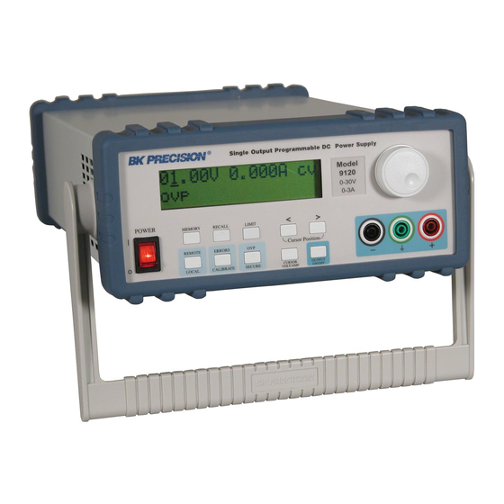
Summary of Contents for BK Precision 9120
- Page 1 Instruction Manual Model 9120, 9121, 9122 & 9123 SINGLE OUTPUT PROGRAMMABLE DC POWER SUPPLY...
-
Page 2: Table Of Contents
Table of contents General Information ……………………………………………. Features …………………………………………………..……… Local Mode Operation ………………….……………………….. Front Panel Description ……………………………………………. Memory Key ………………… ……………………………………. Storing States in Front Panel Mode ………………………………… Recall Key …………………………………………………………. Recalling States in Front Panel Mode ……………………………… Limit Key ………………………………………………………….. Modes of Operation ……………………………………………….. - Page 3 Table of contents Remote Interface ……………………………………..………….. RS-232 Interface …………………………………………………... GPIB / 488 Interface ………………………………………………. Functional Description of GPIB / 488 Interface ………………….. IEEE 488 Addressing ……………………………………………... Bus Description ……………………………………………………. Sending Commands Over GPIB Remote Interface ……………….. Serial Poll Procedure ……………………………………………… Interrogative Commands Over GPIB Interface ……………………...
- Page 4 Table of contents Technical Specifications ……………………………………….… Supplemental Characteristics ……………………………………… Programming Ranges ………………………………………………. Reset Va lues ……………………………………… ………………... Interface Cable ……………………………………………………… Warranty Information ……………………………………….… Service Information ………………………………………….…...
-
Page 6: General Information
General Information Single output programmable DC power supplies. Output voltage is: 0 to 30.0 V for Model 9120 0 to 20.0 V for Model 9121 0 to 60.0 V for Model 9122 0 to 30.0 V for Model 9123 Output current is: 0 to 3.00 A for Model 9120... -
Page 8: Features
Features • Constant Voltage / Constant Current modes of operation This power supply can operate in either constant voltage or constant current modes. The passing from one mode of operation to another is automatic. The active mode of operation is indicated using two indicators: CV –... -
Page 10: Local Mode Operation
Local mode operation Front Panel Description Memory Key Note: Memory location 00 is the power_up state. When the unit is powered up, the power supply will set itself to the settings stored in location 00. Note: If you press the Recall button while turning the power on, the power supply will power up using memory location 01 parameters. - Page 11 Options are selected by pressing Memory key when the desired option is displayed. Memory Menu Overview Store State Store State option will store the current operating state without setting a name for this state. By pressing Memory key, state number and state name (if you set one) are displayed in ascending order by turning the knob.
- Page 12 In this menu Exit option is available, too. In this case, you leave the store operation mode, without changing the name for any state. No Change message will be displayed and the power supply returns to the previous state (the state before entering Memory menu). Important note! Store State option will store the parameters of current operation state in the selected location and will not set a name for the stored state.
-
Page 13: Storing States In Front Panel Mode
Storing States in Front Panel Mode To store an operating state in front panel mode you must follow the steps described bellow: 1. Set the power supply in the desired operating state Stored parameters are: voltage limit, voltage step, overvoltage protection level, state of overvoltage protection circuit, current limit, current step, voltage trigger value, current trigger value, trigger delay value, trigger source, stored state name, state of display, output state. - Page 14 The saving action is realized by pressing Memory key. After that, Done message will be displayed and the power supply returns to normal mode. 4. Select Name State option In order to select this option , Memory key must be pressed again. NameState option allows you to set a name for the selected state.
-
Page 15: Recall Key
Recall Key This key is used to recall an operating state from the storage locations in non- volatile memory. You can recall any operating state from 100 different operating states stored in the non-volatile memory. The recalled state becomes the current operating state. By pressing Recall key, you enter in Recall menu. - Page 16 Exit Exit option allows you to leave the Recall menu, without changing anything. No Change message will be displayed and the power supply returns to the previous state (the state before entering Recall menu). Reset Reset option allows you to reset the power supply without switching off (for more information, please refer to Reset Values section).
-
Page 17: Recalling States In Front Panel Mode
Recalling States in Front Panel Mode To recall an operating state in front panel mode, you must follow the steps described bellow: 1. Enter the Recall menu By pressing Recall key, you enter the Recall menu. By turning the knob, following options are displayed: 01: State 1 02: Test_mode etc. -
Page 18: Limit Key
Limit Ke y The power supply works in 2 modes: Ø Ø Limit mode Ø Ø Normal mode In limit mode limit values of voltage and current are displayed. These are the programmed values (from the front panel or over the remote interface). Limit key is used to get the power supply to limit mode. -
Page 19: Modes Of Operation
Modes of Operation Depending on the application, the power supply can be used as a constant current source or as a constant voltage source. In order to understand constant current and constant voltage operation, a numeric example will be used. Let’s consider a resistor connected to the output terminals of the power supply (R resistor). - Page 20 When the resistor’s value decreases so the output current value becomes equal to the current limit value, power supply will go to constant current operation (see third row of the table). If the resistor value is R = 1 Ù, for U = 5V, using Ohm’s law the output current is 5A.
-
Page 21: Constant Current Operation
Constant Current Operation In constant current operation, current values in limit mode and normal mode are the same, but voltage values are not. To set the power supply in constant current operation, you must follow the steps described bellow: 1. Select the limit values for voltage and current parameters (U ), depending on the application 2. - Page 22 8. Enable the output of the power supply By pressing On / Off key, you enable the output. Power supply goes to normal mode operation and CC indicator will be displayed. In this case constant current operation is active. If CV indicator will be displayed, you must set a higher value for voltage limit. Important note! By turning the knob, voltage and current limit values can be adjusted.
-
Page 23: Constant Voltage Operation
Constant Voltage Operation In constant voltage operation, voltage values in limit mode and normal mode are the same, but current values are not To set the power supply in constant voltage operation, you must follow the steps described bellow: 1. Select the limit values for voltage and current parameters (U ), depending on the application 2. - Page 24 8. Enable the output of the power supply By pressing On / Off key, you enable the output. Power supply goes to normal mode operation and CV indicator will be displayed. In this case constant voltage operation is active. If CC indicator will be displayed, you must set a higher value for current limit. Important note! By turning the knob, voltage and current limit values can be adjusted.
-
Page 25: On / Off Key
On / Off Ke y On / Off key is used to enable / disable the output of the power supply from the front panel. By pressing On / Off key, you alternate these two states: output on / output off. When the output is off, power supply displays: Output off The indicators according to power supply’s state will also be displayed (e.g.:... -
Page 26: Remote / Local Key
Calibration Overview section) If the power supply is in limit mode or normal mode of operation, by pressing Remote / Local key, available interfaces are displayed. Remote Interface Configuration Available interfaces for 912x power-supply models: 9120 9121 9122 9123 RS-232... - Page 27 By turning the knob, following options will be displayed: RS - 232 GPIB / 488 By pressing Remote / Local key once again, the displayed interface is selected and the specific parameters can be set (for RS – 232 interface, baud rate and parity will be set, for GPIB interface GPIB address of the power supply will be set).
-
Page 28: Rs-232 Configuration
RS-232 Configuration Available settings for RS-232 interface: ♦ Baud rate: 1200, 2400, 4800, 9600 (factory setting: 9600) ♦ Parity and data bits: None – 8 data bits (factory setting) Odd – 7 data bits Even – 7 data bits ♦ Number of start bits: 1 bit (cannot be changed) ♦... -
Page 29: Gpib / 488 Configuration
GPIB / 488 Configuration Available setting for GPIB / 488 interface is address of the power supply. An IEEE 488 address can take values from 0 to 30. GPIB address is kept in a non-volatile memory, so when powered on, the last selected address is active. -
Page 30: Remote Mode And Indicators
Remote Mode and Indicators When RS-232 interface is selected, SYSTem:REMote command must be the first sent command. Otherwise, if another command is sent first, Power supply in local mode message will be sent to PC. While in remote interface mode of operation (after sending SYSTem:REMote command), rmt indicator will be displayed. -
Page 31: Errors / Calibrate Key
Errors / Calibrate Key This key has a double function: errors related in normal mode (see this section) and calibration related in calibration mode (see calibration section). There are 2 types of errors: user defined errors and errors defined by SCPI 1999 standard. - Page 32 After several seconds the power supply will go back to normal mode. The err indicator will not be displayed anymore. If there are no errors in the queue and you select Errors option in order to view the errors, the power supply will display: No Errors And then it will return to normal mode.
- Page 33 After the first scrolling of the calibration message, < or > keys must be pressed in order to scroll the message again. Exit Exit option allows you to leave this menu, without changing anything. Exiting message will be displayed and the power supply returns to the previous state (the state before entering this menu).
-
Page 34: Calibration Overview
Calibration Overview Calibration is a procedure that ensures that the power supply will work properly, with parameters specified within Technical Specification section. Before initiating the calibration procedure, the following conditions must be assured: § § disconnect any loads connected to the power supply and turn it on §... -
Page 35: Unsecure Procedure For Calibration
Unsecure Procedure for Calibration To unsecure the power supply, the next steps bust be followed: 1. Turn on the power supply in calibrating mode To enter calibrating mode, you must turn on the power supply while pressing Errors / Calibrate key. You release the key after the long beep. After that, the power supply will display: Calibrating Mode Secured... - Page 36 From this moment you can proceed with calibration (see Calibration procedure section) or you can go back to normal mode operation. From now on, the power supply remains unsecured until you set a new secure code. If the security code you entered is not correct, power supply will display: Security code: invalid for 1 second.
- Page 37 it is finished) does not change anything concerning the secure state of the power supply (secured or unsecured). After you changed the security code or unsecured the power supply, you can go back to normal mode by pressing Local key. (You can come back to calibrating mode only by turning off the power supply and starting it in calibrating mode).
-
Page 38: Hardware Unsecure Procedure For Calibration
Hardware Unsecure Procedure for Calibration This procedure may be used to unsecure the power supply if you forgot the security code. To unsecure the power supply without using the security code, follow the next steps: 1. Turn off the power supply. Disconnect the power cord and all loads connected to the power supply. - Page 39 The power supply remains unsecured until you enter a new security code. Important note! Even if you are in calibrating mode, you cannot set a security code as long as the J6 jumper is in hardware unsecuring position. 5. Set J6 jumper for normal unsecuring mode. Important note! If you turn on the power supply in either normal mode or calibrating mode and J6 jumper is in hardware unsecuring position, error 701 (Calibration security...
-
Page 40: Calibration Procedure
Calibration Procedure Before initiating the calibration procedure, the following conditions must be assured: § § disconnect any loads connected to the power supply and turn it on § § let the power supply turned on for 1 hour, with no loads connected before you start the calibration procedure §... -
Page 41: Voltage Calibration Procedure
Voltage Calibration Procedure After you unsecured the power supply and you pressed Calibrate key, you entered calibrate mode. Volt Zero Scale Calibration 1. Select Volt Zero Scale calibration procedure In order to start voltage calibration procedure, you must select Volt Zero Scale option. -
Page 42: Volt Full Gain Calibration
DAC value displayed by the power supply until the voltmeter indicates the correct voltage value, depending on the model of the power supply (see the table bellow). Power supply model Voltage value for Volt Full Gain calibration 9120 16.3840 V 9121 16.3840 V 9122 32.7700 V 9123 16.3840 V... -
Page 43: Ovp Calibration
OVP Calibration While performing this calibration procedure, the power supply must have no loads connected to the output terminals. 1. Select OVP calibration procedure In order to initiate OVP calibration procedure, you must select OVP option. The power supply will display: Calibrating Mode You select this option by pressing Calibrate key. -
Page 44: Current Calibration Procedure
Current Calibration Procedure Current calibration procedure must be permormed after Voltage calibration procedure. Current Zero Scale Calibration While performing this calibration procedure, the power supply must have no loads connected to the output terminals. 1. Select Curr Zero Scale calibration procedure In order to start current calibration procedure, you must select Curr Zero Scale option. -
Page 45: Current Full Gain Calibration
(see the table bellow). Power supply model Current value for Curr Full Gain calibration 9120 2.62144 A 9121 2.62144 A 9122 1.31072 A... - Page 46 3. Initiate ADC calibration procedure Press Calibrate key. This will initiate ADC calibration procedure. The power supply will display: Curr Full Gain ADC Calibrating After ADC calibration, power supply will return to Calibrate menu. In this moment, the calibration procedure is finished. By presing Local key, the power supply will return to local mode.
-
Page 47: Ovp / Secure Key
The programming range for OVP trip level depends on the model of the power supply (see the table bellow): Power supply OVP min value OVP max value model 9120 33 V 9121 22 V 9122 63 V 9123 33 V The OVP trip level you set is saved by pressing OVP / Secure key. - Page 48 By turning the knob, following options are displayed: OVP On OVP Clear OVP Off Options are selected by pressing OVP / Secure key when the desired option is displayed. OVP On OVP On option enables overvoltage protection circuit. OVP trip level is the level value you programmed on Level option (after you first pressed OVP / Secure key).
- Page 49 supply (see the table above). In this case, the programmed OVP trip level, shown in OVP menu does not change! OVP Clear OVP Clear option is used to clear to OVP condition (for more information about how you get back to normal mode after OVP level was tripped, please refer to the next section).
-
Page 50: Programming Ovp In Front Panel Mode
Programming OVP Circuit in Front Panel Mode If you want to program an OVP trip level and to enable the overvoltage protection circuit using front panel keys, follow the next steps: 1. Turn on the power supply When you turn on the power supply, the overvoltage protection circuit is enabled and OVP trip level is set to maximum available value for OVP parameter, depending on the model of the power supply (see table in the prevous section). -
Page 51: Clearing Overvoltage Condition
Clearing Overvoltage Condition There are three ways of clearing the OVP condition: Ø By increasing OVP trip level and clearing the OVP condition Ø By decreasing the output voltage and clearing the OVP condition Ø By disabling OVP circuit and clearing the OVP condition Attention! The latter solution disables the OVP circuit, but the first and the second don’t! In this section we will describe the steps you must follow to clear the OVP... - Page 52 Clear OVP Condition by Increasing OVP Trip Level 1. Enter the OVP menu By pressing OVP / Secure key, you enter the OVP menu. 2. Adjust OVP trip level When you enter OVP menu, OVP trip level is displayed. Here, you set OVP trip level to a level higher than the programmed voltage value (U 3.
- Page 53 Clear OVP Condition by Decreasing the Output Voltage 1. Decrease the output voltage level bellow OVP trip level Press Limit key and enter limit mode. Limit values of voltage and current will be displayed. ovp and lmt indicators will also be displayed. Adjust for output voltage limit to a lower value than the OVP trip level.
- Page 54 Clear OVP Condition by Disabling OVP Circuit 1. Disable OVP circuit By pressing OVP / Secure key, you enter OVP menu. Here you disable OVP circuit by turning the knob and selecting OVP Off option. OVP Off It doesn’t matter if you change or not OVP trip level as long as you disable the OVP circuit.
-
Page 55: Rear Panel Description
Rear Panel Description On the rear panel of the power supply there are: § § RS-232 interface connector § § AC inlet § § Power-line fuse-holder assembly § § Rear output terminals. The sensing terminals (+s and -s) are connected to the output terminals of the power supply by jumpers. -
Page 56: Remote Interface
Remote Interface For remote communication, there are two available interfaces: GPIB / 488 interface and RS-232 interface. The selected interface and the coresponding settings are saved in a non-volatile memory and does not change after the power supply is turned off or after a *RST command. Only one interface can be active at a time. -
Page 57: Gpib / 488 Interface
GPIB / 488 Interface GPIB / 488 interface availability for different models: 9120 9121 9122 9123 RS-232 Standard Standard Standard Standard GPIB / 488 Optional Optional Optional Standard GPIB (General Purpose Interface Bus) interface is also known as IEEE 488. -
Page 58: Functional Description Of Gpib / 488 Interface
Functional Description of GPIB Interface Devices from the interface are classified into 3 types: Listener: a device capable of receiving data over the interface when addressed to listen by the Active Controller. There can be up to 14 Listeners on the bus at one time. Usually the Active Controller will be the Talker, while a single device is the Listener. -
Page 59: Ieee 488 Addressing
IEEE 488 Addressing An IEEE 488 address can take values from 0 to 30. When supplied from the factory, power supply’s GPIB address is 5. An IEEE 488 device has a Listen address and a Talk address. Listen address and Talk address bytes are different. Listen address is defined by adding decimal value of 32 to the address. -
Page 60: Bus Description
Bus Description The interface signal lines are organized into three functional groups: Data lines (8 lines) Handshake lines (3 lines) General bus management lines (5 lines) The bus signal lines use low true logic protocol. Data lines: allow transfer of one byte at a time. Bytes are transferred over the interface in a byte-serial, bit-parallel manner. - Page 61 General bus management lines: ATN, IFC, REN, SRQ, EOI and they are used by the Active Controller or System Controller to manage GPIB interface SRQ (Service Request): This line is used by any device from the bus. when is set true (low), the device notifies the Controller that it needs servicing a request.
-
Page 62: Sending Commands Over Gpib Remote Interface
when ATN line is false (high), the bus is in data mode and data bytes are transferred over the interface. These bytes may be SCPI commands sent by the addressed Talker to the addressed Listeners. or a response sent by a previously interrogated Listener (eg: response to an interogative command). -
Page 63: Serial Poll Procedure
Serial Poll Procedure When serial poll procedure is initiated, a device is addressed to talk and Active Controller sends Serial Poll Enable command (ATN line is low, because addresses and GPIB command bytes are transferred over the interface). The addressed device sends back to Active Controller a Status Byte (ATN line is high, because data bytes are transferred over the interface). -
Page 64: Commands Sent Over Remote Interface
Commands Sent Over Remote Interface There are several types of commands that can be sent over the remote interface, in order to control the power supply: § § SCPI (Standard Commands for Programmable Instruments) commands these commands are defined in the Power Supply Instrument Classes of the 1999 SCPI standard. -
Page 65: Introduction To Scpi Language
Introduction to SCPI Language Here are some conventions used in SCPI standard: ♦ A command consists of a command keyword (command name) and a parameter (it may be optional or not) ♦ Lower case and upper case letters are considered equivalent ♦... - Page 66 SCPI Command Terminators A command string sent to the power supply must terminate with a new line character (ASCII decimal code of 10) or a a carriage return character (ASCII decimal code of 13). For multiple commands sent in a single message, command separator is semicolon character (03b h).
-
Page 67: Scpi Commands
SCPI Commands DISPLAY Subsystem :DISPlay [:WINDow][:STATe ] {OFF|ON} [:WINDow][:STATe ]? [:WINDow]:TEXT[:DATA] <quoted string> [:WINDow]:TEXT[:DATA]? [:WINDow]:TEXT:CLEar MEASure Subsystem :MEASure :CURRent[:DC]? [:VOLTage][:DC]? MEMory Subsystem MEMory:STATe :NAME <numeric value>,<quoted string> :NAME? <numeric value> OUTPut Subsystem :OUTPut [:STATe] {OFF|ON} [:STATe]? SOURce Subsystem [:SOURce] :CURRent[:LEVel][:IMMediate][:AMPLitude] {<current>|MIN|MAX|UP|DOWN} :CURRent[:LEVel][:IMMediate][:AMPLitude]? [MIN|MAX] :CURRent[:LEVel][:IMMediate]:STEP[:INCrement] {<numeric value>|DEFault} :CURRent[:LEVel][:IMMediate]:STEP[:INCrement]? [DEFault]... - Page 68 STATus Subsystem STATus:QUEStionable [:EVENt]? :ENABle <enable value> :ENABle? SYSTem Subsystem :SYSTem :BEEPer[:IMMediate] :COMMunicate:GPIB:RDEVice:ADDRess <numeric value> :COMMunicate:GPIB:RDEVice:ADDRess? :ERRor? :INTerface GPIB|RS232 :VERSion? TRIGger Subsystem INITiate[:IMMediate] TRIGger[:SEQuence]:DELay {<seconds>|MIN|MAX} TRIGger[:SEQuence]:DELay? [MIN|MAX] TRIGger[:SEQuence]:SOURce {BUS|IMM} TRIGger[:SEQuence]:SOURce? *TRG Non-SCPI commands SET {<voltage>|DEF|MIN|MAX}[,<current>|DEF|MIN|MAX] SET? CALibration:MESSAGE <quoted string> CALibration:MESSAGE? SYSTem:REMote...
- Page 69 IEEE 488.2 commands *CLS *ESE <enable value> *ESE? *ESR? *IDN? *OPC *OPC? *PSC {0|1} *PSC? *RCL {0 | 1 | 2 | … | 99} *RST *SAV {0 | 1 | 2 | … | 99} *SRE <enable value> *SRE? *STB? *TRG IEEE 488 bus commands...
-
Page 70: Scpi Commands Overview
SCPI commands overview DISPlay Subsystem This subsystem controls the presentation of textual information and measurement data. :DISPlay[:WINDow][:STATe] {0|1|OFF|ON} This command turns power supply’s display off and on. When the display is off, only indicators are displayed. When the display is on, power supply is in nomal mode (measured or programmed values of voltage and current are displayed.). -
Page 71: Measure Subsystem
MEASure Subsystem This subsystem contains commands that allow you to measure the current and voltage to the output terminals of the power supply. :MEASure:CURRent[:DC]? This command queris the current measured to the output terminals of the power supply. :MEASure[:VOLTage][:DC]? This command queries the voltage measured to the output terminals of the power supply. -
Page 72: Memory Subsystem
MEMory Subsystem This subsystem contains commands that manage power supply’s memory locations. MEMory:STATe:NAME <numeric value>,<quoted string> This command allows you to name a memory location. The numeric value parameter gives the number of the memory location that will be named. It can be between 0 and 99. The quoted string contains the name of the location. -
Page 73: Output Subsystem
OUTPut Subsystem This subsystem controls the output of the power supply. :OUTPut[:STATe] {0|1|OFF|ON} This command enables and disables the output of the power supply. You can replace off | on parameters with 0 | 1 numeric values. When output is enabled, the power supply will display voltage and current value measured on the output terminals of the power supply. -
Page 74: Source Subsystem
SOURce Subsystem According to SCPI standard, SOURce node is optional, so the devices which are primarily sources accept shorter commands. This subsystem contains commands that program power supply parameters or commands that query programmed power supply parameters (for example: programmed values for current and voltage, programmed values for step current and step voltage, lowest or highest value possible to program for current and voltage etc. - Page 75 CURR:STEP 0.2 ;program current step value CURR UP ;increase output current CURR:STEP 0.5 ;program current step value CURR DOWN ;decrease output current Note: If no step value was programmed before CURR UP or CURR DOWN commands, default step value (0.001 A) will be used. CURRent[:LEVel][:IMMediate]:TRIGgered[:AMPLitude] {<current>|MIN|MAX} This command allows you to program the current trigger value, which is transfered to the output terminals when a trigger signal occurs.
- Page 76 :VOLTage[:LEVel][:IMMediate]:STEP[:INCrement] {<numeric value>|DEFault} This command allows you to set the voltage step for VOLT UP or VOLT DOWN command. The default value for voltage step is 10 mV. :VOLTage[:LEVel][:IMMediate]:STEP[:INCrement]? [DEFault] This command queries the programmed voltage step value (if no parameter specified), or the default voltage step value (if DEFault parameter is specified within the command) for voltage.
- Page 77 :VOLTage:PROTection[:LEVel]? [MIN|MAX] This command queries the programmed voltage protection level. When using MIN or MAX parameters, the power supply returns the lowest or the highest value that is possible to program for voltage protection level, depending on the parameter. :VOLTage:PROTection:S TATe {0|1|OFF|ON} This command allows you to disable / enable the overvoltage protection circuit.
- Page 78 OVP circuit is enabled. If output voltage becomes equal or greater than OVP programmed trip level, OVP circuit trips and Over Voltage and Output Off messages will be displayed. Output voltage will become 0 V. It is not necessary to check every setting with the interogative command! This is an example of how you use this commands.
- Page 79 Let’s say that the output voltage is lower than 10V. No load connected. VOLT:PROT 10 ;program OVP trip level VOLT:PROT:STAT ON ;enable OVP circuit If OVP circuit is already enabled, you don’t have to enable it again! VOLT 10 ;OVP circuit tripped When output voltage becomes equal or greater than OVP trip level (here is 10V), OVP circuit trips.
- Page 80 When output voltage becomes equal or greater than OVP trip level (here is 8V), OVP circuit trips. Output is disabled and Over Voltage message will be displayed. VOLT:PROT:STAT OFF ;Disable OVP circuit Attention: if you have anything connected to the output terminals of the power supply, it it strongly recommended that you disconnect it before disabling OVP circuit (because you don’t change output level and this it may harm your connected circuitry)
-
Page 81: Status Subsystem
STATus Subsystem This subsystem controls SCPI defined status reporting structures. STATus:QUEStionable:EVENt? This command queries Status Questionable Even Register. The power supply returns a decimal value which is the binary weighted sum of all bits of the register. Reading Status Questionable Event Register does not clear it. STATus:QUEStionable:ENABle <enable value>... -
Page 82: System Subsystem
SYSTem Subsystem This subsystem contains functions that are not directly related to power supply performance. :SYSTem:BEEPer[:IMMediate] This command determines the power supply to generate a beeper right after she received this command. SYSTem:COMMunicate:GPIB:RDEVice:ADDRess <numeric value> This command will change the power supply’s GPIB address. SYSTem:COMMunicate:GPIB:RDEVice:ADDRess? This command queries the power supply’s GPIB address. -
Page 83: Trigger Subsystem
TRIGger Subsystem The power supply has a trigger subsystem, so voltage and current values can be changed when receiving a trigger signal. Depending on the trigger source selected, this change takes place immediately (when receiving the trigger signal), or after a time period equal with the delay you set (a time period from the moment the power supply receives the trigger signal) To activate the trigger subsystem you must follow the steps described bellow:... - Page 84 At power on reset or *RST command, voltage and current trigger values are the programmed values (values displayed in limit mode) until you explicitly program them with the desired values. So before programming voltage and current values, :VOLTage[:LEVel][:IMMediate]:TRIGgered[:AMPLitude]? :CURRent[:LEVel][:IMMediate]:TRIGgered[:AMPLitude]? commands return the programmed values for voltage and current. Trigger programmed values are available until a new programming command for a certain parameter, no matter how many times you use the trigger subsystem.
- Page 85 Here are described the commands used to set trigger subsystem’s parameters: :CURRent[:LEVel][:IMMediate]:TRIGgered[:AMPLitude] <current>|MIN|MAX} This command allows you to program t h e current trigger value, which is transfered to the output terminals when a trigger signal occurs. By programming this value, you don’t change the current programmed value. Instead of a numeric value, you can use MIN or MAX parameters.
- Page 86 MAX parameter allows you to set the trigger delay to 36,000 seconds (equivalent to 10 hours). At power on reset or after *RST command this value is set to 0 seconds. :TRIGger:DELay? [MIN | MAX] This command queries the trigger delay programmed value. When using MIN or MAX parameters, the power supply returns the lowest and the highest value that are possible to program for trigger delay.
-
Page 87: Non_Scpi Commands
Non-SCPI Commands SET {<voltage>|DEF|MIN|MAX}[,<current>|DEF|MIN|MAX] This is a non-SCPI command. This command allows you to program output voltage and current values in the same time, using one command only. Using this command, you can program output voltage or output voltage and current values. -
Page 88: Ieee 488.2 Commands
IEEE 488.2 Commands The 488.2 specifications include some instrument commands and a status information scheme. For more information about SCPI Status Registers, see Status Reporting Overview section. *CLS (Clear Status) This command clears Status Byte Register and all the Event Registers summarized in Status Byte, such as Questionable Status Event Register and Standard Event Register. - Page 89 *OPC? The power supply returns an ASCII “1” after all operations, including this command are executed. *RST This command allows you to reset the power supply. The power supply reset can be achieved by sending this command or by selecting RESET option from the Recall menu (Recall key). The power supply reset values for different parameters are listed in Technical Specifications section.
-
Page 90: Ieee 488 Bus Commands
IEEE 488 Bus Commands These comands are GPIB / 488 interface specific commands. In command mode (ATN line low), the power supply can receive three classes of commands: Talk and Listen addresses: They define which device from GPIB interface will be the active Talker and which devices will be the active Listeners. - Page 91 Addressed commands: they are byte commands sent by the Controller only to the addressed Listeners. So these commands are sent with address bytes. GET (Groupe Execute Trigger) This command is equivalent to the *TRG command. For more information about trigger subsystem of the power supply, please refer to Trigger Subsystem section.
-
Page 92: Ascii Table For Gpib
ASCII Table For GPIB Ctrl “ & ‘ < >... - Page 93 ‘ SC10 SC11 SC12 SC13 SC14 SC15 SC16 SC17 SC18 SC19 SC20 SC21 SC22 SC23 SC24 SC25 SC26 SC27 SC28 SC29 SC30 SC31...
-
Page 94: Scpi Status Registers
The SCPI Status Registers Status reporting scheme is described in this section. Questionable Status Event Register Enable Register Output Buffer Voltage Current Not Used Not Used Not Used Not Used Not Used Not Used Not Used Overvolt Status Byte Not Used Summary Reg Enable Reg Not Used Not Used... - Page 95 Event Register is a read only register. Bits in an event register are set depending on the state of the power supply. An event register is cleared after its value was queried or by sending *CLS command. A *RST command does not clear event registers. When an event register is queried, the power supply returns a decimal value, which is the binary –...
- Page 96 Standard Event Register Standard Event Register reports different instrument events, such as: query errors, device dependent error, execution errors, command errors, power on event. A set bit indicates that an event of the specified type occurred. Bit 0 - OPC (Operation Complete) - indicates that all previous commands have been executed and the device is ready to accpet new commands - this bit is set only after an *OPC command...
- Page 97 Status Byte Register Status Byte Register reports conditions from the defined status registers, depending on the bits from the enable registers. So clearing an event register will clear the coresponding bits from the Status Byte Register. Bits 0..2 - Not used - always set to 0 Bit 3 - QUES...
-
Page 98: Error Messages
Error Messages There are 2 kinds of errors that will be generated by the power supply: ♦ standard errors (errors defined by SCPI standard, in [-299,-100] interval) ♦ device specific errors (user defined errors, in [-399,-300] or [1,32767] interval) Following types of errors may occur: ♦... - Page 99 Error -123: Exponent too large The numeric parameter received has an exponent larger than 32,000. Error -124: Too many digits The decimal numeric parameter has a mantissa which contains more than 255 digits, excluding leading zeros Error - 128: Numeric data not allowed A legal numeric data element was received, but is not the right data element for the header Error -131: Invalid suffix...
-
Page 100: Execution Errors
Execution Errors Error – 211: Trigger ignored *TRG command was received, but it was ingnored because trigger subsystem was not initiated (using INITiate command). Error - 222: Data out of range The numeric parameter value is out of range. Error - 223: Too much data A legal string program data element contains more data than the device could handle due to memory or due to device specific requirements. -
Page 101: Self-Test Errors
The communication session was interrupted before it was finished (no terminator was sent). Err -410: Query interrupte d A command was received before the response to the previous interrogative command was sent. Err -420: Query unterminated The power supply was addressed to talk (to send data over the interface), but it didn’t previously receive a command which sends data to the output buffer (an interrogative command). - Page 102 Error 611: EEPROM absent Error 612: ADC offset register V checksum failed Error 613: ADC offset register I checksum failed Error 614: DAC offset register V checksum failed Error 615: DAC offset register I checksum failed Error 616: ADC full gain register V checksum failed Error 617: ADC full gain register I checksum failed Error 618: DAC offset register OVP checksum failed Error 619: DAC V step register checksum failed...
-
Page 103: Calibration Errors
If one of the errors above is generated, the power supply must be turned off and then turned on. If one of these errors is generated again, the power supply must be delivered to B&K Precision for service. Calibration Errors Here are calibration error messages generated by the power supply: Error 637: Secure code checksum failed If this error is generated, the power supply must be unsecured using hardware... - Page 104 Error 724: DAC V step register memory bad Error 725: ADC full gain register V out of range Error 726: ADC full gain register V memory bad Error 731: DAC offset register OVP start value out of range Error 732: DAC offset register OVP out of range Error 733: DAC offset register OVP memory bad Error 734: DAC OVP step register start value out of range Error 735: DAC OVP step register out of range...
- Page 105 CC fault CV fault In this case, the power supply must be turned off and then turned on. If the messages persist, the power supply must be delivered to B&K Precision for service.
-
Page 106: Technical Specifications
Technical specifications Table 1: Technical S pecifications for 9120 Model Parameter 9120 Output Ratings (at 0 ° - 40 ° C) 0 to + 30 V / 0 to 3 A < Programming Accuracy [1] Voltage 0.05%+10 mV 12 months ( at 25 ° C±5 ° C) ± (% of Current <... - Page 107 Table 2: Technical S pecifications for 9121 Model Parameter 9121 Output Ratings (at 0 ° - 40 ° C) 0 to + 20 V / 0 to 5 A Programming Accuracy [1] Voltage < 0.05%+10 mV 12 months ( at 25 ° C±5 ° C) ± (% of Current <...
- Page 108 Table 3: Technical S pecifications for 9122 Model Parameter 9122 Output Ratings (at 0 ° - 40 ° C) 0 to + 60 V / 0 to 2.5 A Programming Accuracy [1] Voltage < 0.05%+10 mV 12 months ( at 25 ° C±5 ° C) ± (% of Current <...
- Page 109 Table 4: Technical Specifications for 9123 Model Parameter 9123 Output Ratings (at 0 ° - 40 ° C) 0 to + 30 V / 0 to 5 A Programming Accuracy [1] < Voltage 0.05%+10 mV 12 months ( at 25 ° C±5 ° C) ± (% of Current <...
- Page 110 Accuracy specifications are after an 1-hour warm-up with no load and calibration at 25 ° C Transient Response Time Less than 50µsec for output to recover to within 15mV following a change in output from full load to half load or vice versa. Settling time Less than 90msec for the output voltage to change from 1% to 99% or vice versa following the receipt of VOLTAGE or SET command via RS-232 or...
-
Page 111: Supplemental Characteristics
Supplemental Characteristics Remote sensing capability Voltage drop Up to 1V per each lead Load regulation Add 5mV to spec for each 1-volt change in the + outputs lead due to load current change. Load voltage Substract voltage drop in load leads from specified output voltage rating. - Page 112 Please ensure correct insertion and fuse rating. Fuse ratings: Model 9120: 3.15A/250V for 115Vac, 2A / 250V for 230V Model 9121: 3.15A/250V for 115Vac, 2A /250V for 230V Model 9122: 5A/250V for 115Vac, 3.15A / 250V for 230V Model 9123: 5A/250V for 115Vac, 3.15A / 250V for 230V...
-
Page 113: Programming Ranges
Here are programming ranges, programming values for MINimum, MAXimum, DEFault parameters and reset state: Table 5: Programming ranges for voltage parameter Voltage Model Model Model Model parameters 9120 9121 9122 9123 Programming 0 to 30.5V 0 to 20.5V 0 to 30.5V 0 to 30.5V... -
Page 114: Reset Values
Here are the power supply parameter values after a *RST command or after recalling Reset state. Table 8: Reset values for power supply parameters Power supply Model Model Model Model parameters 9120 9121 9122 9123 Voltage Voltage step 0.01 V 0.01 V 0.01 V 0.01 V... -
Page 115: Interface Cable
Interface Cable In order to command the power supply over the remote interface, you must connect it to a computer terminal. Usually, the computer terminals are DTE (Data Terminal Equipment). The power supply is also DTE, so you need a DTE to DTE interface cable. These cables are called null-modem or crossover cables. -
Page 116: Warranty Information
Limited One -Year Warranty B&K Precision Corp. warrants to the original purchaser that its product and the component parts thereof, will be free from defects in workmanship and materials for a period of one year from the data of purchase. B&K Precision Corp. - Page 117 This warranty gives you specific rights and you may have other rights, which vary from state-to-state. Model Number: ______________ Date Purchased: __________ 22820 Savi Ranch Parkway Yorba Linda, CA 92887 714.921.9095 714.921.6422 Facsimile...
-
Page 118: Service Information
Service Information Warranty Service: Please return the product in the original packaging with proof of purchase to the below address. Clearly state in writing the performance problem and return any leads, connectors and accessories that you are using with the device. Non-Warranty Service: Return the product in the original packaging to the below address. - Page 119 22820 Savi Ranch Parkway Yorba Linda, CA 92887 TEL: 714-921-9095 PN: 481-533-9-001 FAX: 714-921-6422 Printed in Romania ©2004 B&K Precision Corp. www.bkprecision.com...
Need help?
Do you have a question about the 9120 and is the answer not in the manual?
Questions and answers