
Related Manuals for BK Precision 9103


Summary of Contents for BK Precision 9103
- Page 1 Model 9103 and 9104 Multi-Range DC Power Supply USER MANUAL 1.800.561.8187 information@itm.com www. .com...
-
Page 2: Safety Summary
Safety Summary The following safety precautions apply to both operating and maintenance personnel and must be followed during all phases of operation, service, and repair of this instrument. Before applying power to this instrument: Read and understand the safety and operational information in this manual. Apply all the listed safety precautions. - Page 3 Category II (CAT II): Measurement instruments whose measurement inputs are meant to be connected to the mains supply at a standard wall outlet or similar sources. Example measurement environments are portable tools and household appliances. Category III (CAT III): Measurement instruments whose measurement inputs are meant to be connected to the mains installation of a building.
- Page 4 Do not alter or defeat the ground connection. Without the safety ground connection, all accessible conductive parts (including control knobs) may provide an electric shock. Failure to use a properly-grounded approved outlet and the recommended three-conductor AC line power cable may result in injury or death. Unless otherwise stated, a ground connection on the instrument's front or rear panel is for a reference of potential only and is not to be used as a safety ground.
- Page 5 Measurements made by this instrument may be outside specifications if the instrument is used in non-office-type environments. Such environments may include rapid temperature or humidity changes, sunlight, vibration and/or mechanical shocks, acoustic noise, electrical noise, strong electric fields, or strong magnetic fields. Do not operate instrument if damaged If the instrument is damaged, appears to be damaged, or if any liquid, chemical, or other material gets on or inside the instrument, remove the instrument's power cord, remove the...
- Page 6 when the covers are removed. To avoid injuries, always disconnect the power cord from the instrument, disconnect all other connections (for example, test leads, computer interface cables, etc.), discharge all circuits, and verify there are no hazardous voltages present on any conductors by measurements with a properly-operating voltage-sensing device before touching any internal parts.
- Page 7 Cooling fans This instrument contains one or more cooling fans. For continued safe operation of the instrument, the air inlet and exhaust openings for these fans must not be blocked nor must accumulated dust or other debris be allowed to reduce air flow. Maintain at least 25 mm clearance around the sides of the instrument that contain air inlet and exhaust ports.
-
Page 8: Compliance Statements
Compliance Statements Disposal of Old Electrical & Electronic Equipment (Applicable in the European Union and other European countries with separate collection systems). This product is subject to Directive 2002/96/EC of the European Parliament and the Council of the European Union on waste electrical and electronic equipment (WEEE), and in jurisdictions adopting that Directive, is marked as being put on the market after August 13, 2005, and should not be disposed of as unsorted municipal waste. -
Page 9: Ce Declaration Of Conformity
CE Declaration of Conformity The power supply meets the requirements of 2006/95/EC Low Voltage Directive and 2004/108/EC Electromagnetic Compatibility Directive. Low Voltage Directive EN 60950-1 EN 61010-1 EMC Directive EN 55011 EN 55022 EN 55024 EN61000-3-2 EN61000-3-3 EN61000-6-1 1.800.561.8187 information@itm.com www. -
Page 10: Safety Symbols
Safety Symbols Refer to the user manual for warning information to avoid hazard or personal injury and prevent damage to instrument. Electric Shock hazard On (Supply). This is the AC mains connect/disconnect switch on the front of the instrument. Off (Supply). This is the AC mains connect/disconnect switch on the front of the instrument. -
Page 11: Table Of Contents
Contents Safety Summary ........................2 Compliance Statements ......................8 CE Declaration of Conformity ....................9 Safety Symbols ........................10 1 General Information ......................13 1.1 Product Overview ....................... 13 1.2 Package Contents ....................... 13 1.3 Input Power ........................14 1.4 Fuse Requirements ......................14 1.5 Fuse Replacement ...................... - Page 12 Changing Ammeter to Wattmeter .................. 22 Key Lock Function ......................22 Changing the values of UVL and UCL ................23 4.2 Preset Mode ........................23 4.3 Transient Mode ........................24 Step Size (seconds) ......................25 Transition time: ....................... 25 Select First Step ....................... 26 Number of Cycles ......................
-
Page 13: General Information
1 General Information 1.1 Product Overview B&K Precision models 9103 and 9104 are multi-range power supplies differing from conventional power supplies because voltage and current limits are varied to allow maximum rated power to be delivered at any operating point. Contrast this to a conventional power supply which has a maximum voltage and maximum current rating -- all operating points must fall inside these limits. -
Page 14: Input Power
An AC input fuse is necessary when powering the instrument. Below is a table of the fuse required for all models operating with either 110 VAC or 220 VAC input. Model Fuse Specification (110 - 240VAC) 9103 T5AL 250V 9104 T5AL 250V Table 1 - Fuse Specifications 1.5 Fuse Replacement... -
Page 15: Controls And Indicators
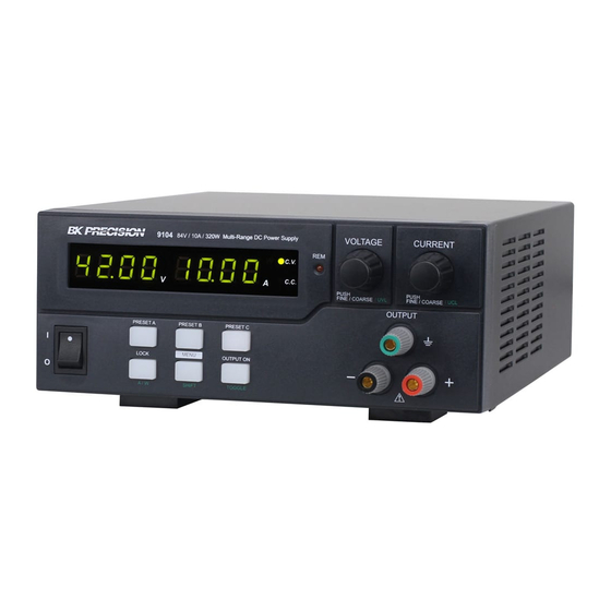
2 Controls and Indicators 2.1 Front Panel Figure 2 - Front Panel ① LED panel meter display with CV/CC/W (constant current/constant voltage/power) indicator ② Remote Control Indicator (shows Remote Control/USB mode) ③ Output Voltage Control Knob (UVL upper voltage limit) ④... -
Page 16: Rear Panel
2.2 Rear Panel Figure 3 - Rear Panel ⑧ Remote Sense Shorting the remote sensing terminal or connecting the sense terminals with reversed polarity will damage the power supply. ⑨ Thermostatically controlled cooling Fan ⑩ Analog Remote Control Terminal ⑪ USB Port ⑫... -
Page 17: Operating Instructions
3 Operating Instructions 3.1 Safety Precautions • Do not use this power supply near water. • Do not operate or touch this power supply with wet hands. • Do not open the casing of the power supply when it is connected to AC mains. •... -
Page 18: Using Keypad And Control Knobs
3.2 Using Keypad and Control Knobs Keypad An activated button will be illuminated. The three buttons in the lower row have dual functions which work in conjunction with other lower buttons or with the voltage, current control knobs as defined by the green labels. Throughout this manual the Menu button also acts as the Shift button. -
Page 19: Deactivating Remote Control Mode
b) Turn the Voltage control knob until the panel meter displays wording rC SEt as below. Figure 4 - Remote Control Display c) Press the Voltage control knob to confirm the entry into remote control mode. d) Turn the Current control knob to select remote ON or OFF. e) Press the Voltage control knob to confirm and return to Set menu. -
Page 20: Changing Ammeter To Wattmeter
Changing Ammeter to Wattmeter. This function is only valid when the output on/off is set to on. a) Press Output ON/OFF to ON. b) Press the “Shift”/ (Manual) key and then press the “Lock/Unlock” key. c) Note the orange “W” next to the green “CV” to indicate the power in watts is being displayed. -
Page 21: Operating Modes
4.1 Normal Mode Model Output Voltage Range Total Rated Current Number 9103 0 - 42V (I ≤ 7.6A for 42V) 0 - 20A (V ≤ 16V for 20A) 9104 0 - 84V (I ≤ 3.8A for 84V) 0 - 10A (V ≤ 32V for 10A) Table 2 - Power Ranges Maximum values of voltage and current are limited by the maximum output power of 320 W. -
Page 22: Turn On The Power Supply
Imax(A) mΩ/meter 13.2 33.5 52.8 Table 3 - Wire Gauges Before connecting wires to the output terminals, turn OFF the power supply to avoid damage to the instrument and the device under test (DUT). For safety, load wires must have a wire gauge size large enough to prevent overheating when the power supply operates at maximum short circuit output current. -
Page 23: Changing The Values Of Uvl And Ucl
The “Lock/Unlock” key lights up when the keys are locked. Changing the values of UVL and UCL These functions are designed to give additional protection for voltage sensitive and/or current- sensitive loads. When the voltage or current at the output terminal exceed the UVL or UCL set limits, the output will be turned off. -
Page 24: Transient Mode
Always check the voltage & current level of the Preset before setting output to on when connected to a load. Factory Output Voltage Output Current Default Preset A 9103: 5V 9103: 20A 9104: 5V 9104: 10A Preset B 9103: 13.8V 9103: 20A 9104: 13.8V... -
Page 25: Step Size (Seconds)
Note: The Transient Mode is independent from the output state. It is recommended to set the voltage and current to zero before enabling this mode. Turn the output off by pressing the OUTPUT ON button (make sure the backlight is off). ... -
Page 26: Select First Step
Figure 8 - Transition Time Select First Step This option allows the user to select a transition to start the sequence. rUN A_b rUN b_A rUN A_C rUN C_A rUN b_C rUN C_b Options: Figure 9 - Selecting First Step Number of Cycles Runt means number of cycles the power supply will run before stopping. - Page 27 Turn the output off by pressing the OUTPUT ON button (make sure the backlight is off). Set the voltage and current to 0 V and 0 Amps. Turn the output on by pressing the OUTPUT ON button (make sure the backlight is on), now, current and voltage are set to zero.
- Page 28 Figure 11 - Sequence Mode: Example 1 Figure 12 – Sequence Mode: Example 1 Example 2: Generating a Ramp a) Make sure that the voltage and current of the Presets have been set first. In this example, we use Preset A = 5V, Preset B = 10V b) Press and hold the Menu button (~4 seconds).
- Page 29 Figure 13 - Sequence Mode: Example 2 Example 3: Triangular Using the same procedure as above 13. Set A = 5V , B = 10 V 14. Set Δt a-b = 3 seconds , Set Δt b-a = 3 seconds 15.
- Page 30 Figure 15 - Transient Mode: Example 4 Note: Waveform generation can be operated via the remote programming software with preview of the waveform and data logging of the output. 1.800.561.8187 information@itm.com www. .com...
-
Page 31: Analog Remote Control
4.4 Analog Remote Control There are two methods to remotely control the voltage and current output of these units: voltage control and resistance control. Note: Both analog methods require the remote control connector plug to be set up in order for analog remote control mode to be functional;... -
Page 32: Analog Remote Control Methods And Set Ups
Analog Remote Control Methods and Set Ups After entering into Remote Control Mode, the following external set ups can be selected. There are two methods for remote control of current and voltage adjustment. Both methods require both the current remote control part and the voltage remote control part to be set up and in use at the same time in order for the analog remote control mode to be functional. -
Page 33: Analog Remote Control: Voltage Control
d) Plug the remote connector plug into the analog remote control terminal of the power supply. e) Secure the remote connector plug to the terminal socket by screwing in the connector ring (Figure 19). Figure 19 - Connector Ring Then, you can choose one of the following two methods to use the analog remote control feature: ... - Page 34 Table 5 – Analog Remote Control Connector Pinout: Voltage Control Do not input higher than 5 V, otherwise the overvoltage protection (OVP) will be triggered. Steps to configure Voltage Control: 1. Make sure the load is disconnected and the power supply is OFF. 2.
- Page 35 Figure 20 -Variable 5 kΩ Resistors Setup FUNCTIONS REMARKS Internal DC +5 V Resistor end Voltage Adjust Variable part of resistor Current Adjust Variable part of resistor Ground Resistor end Output OFF Short to Ground Table 6 - Analog Remote Control Connector Pinout: Voltage Control 3.
-
Page 36: Remote Enable And Disable The Output
6. Short circuit the main output with 12AWG wire and check the display for CC setting by varying the 5 kΩ variable resistor for current adjustment. 7. Switch off the power supply. Remote Enable and Disable the Output This remote output on/off control can be activated in any of the following modes: Normal, Preset, Remote, and Set mode. -
Page 37: Remote Sensing
5 Remote Sensing Never short the Remote Sensing Terminal. An incorrect disconnection sequence will damage the Power Supply. Always disconnect the Remote Sensing Terminal first. DO NOT USE Output On Off on front panel or by remote operation. ... -
Page 38: Protection Faults
Listen for the self-test fan noise from the cooling fan when you turn on the unit again. If you cannot hear this self-test fan noise on power-up, then the fan is at fault; do not use the power supply and contact BK Precision. 1.800.561.8187 information@itm.com... -
Page 39: Ocp: Over Current Protection
To reset this warning, disconnect the load and press the Output ON/OFF key. Reconnect the load and the power supply should resume normal operation once power is turned on again. If this problem cannot be fixed, please contact and consult BK Precision. 1.800.561.8187 information@itm.com www. -
Page 40: Specifications
7 Specifications Models 9103 9104 Output Rating Variable Output Voltage 0 - 42 VDC 0 - 84 VDC Variable Output Current 0 - 20 A 0 - 10 A Maximum Output Power 320 W Voltage Regulation Load (0 - 100% of rated current) ≤... - Page 41 ≤ 372 W (230 VAC) ≤ 367 W (230 VAC) Power Consumption (typical) ≤ 385 W (100 VAC) ≤ 380 W (100 VAC) ≥ 86% (230 VAC) ≥ 87% (230 VAC) Efficiency (typical) ≥ 83% (100 VAC) ≥ 84% (100 VAC) Power Factor Control Power factor correction >...
Need help?
Do you have a question about the 9103 and is the answer not in the manual?
Questions and answers
Hi, I have a BK Precision 9103 power supply. I want to be able to turn the power supply on/off and it should output default voltage and current without me having to press the output button on every power cycle. How do I do that? Thanks
The BK Precision 9103 power supply does not support automatic output activation at power-on without pressing the OUTPUT ON button. The output must be manually turned on by pressing the OUTPUT ON button after powering up.
This answer is automatically generated