Table of Contents
Advertisement
Quick Links
Advertisement
Table of Contents

Related Manuals for Supermicro Supero H8SME-F


Summary of Contents for Supermicro Supero H8SME-F
- Page 1 ® UPER H8SME-F USER’S MANUAL Revision 1.0b...
- Page 2 Clara County in the State of California, USA. The State of California, County of Santa Clara shall be the exclusive venue for the resolution of any such disputes. Supermicro's total liability for all claims will not exceed the price paid for the hardware product.
- Page 3 AMD Socket AM3+ type processor with up to 32 GB of DDR3 Unbuffered ECC DDR3-1600/1333/1066 Mhz SDRAM in four (4) DIMMs. Please refer to the motherboard specifi cations pages on our web site for updates on supported processors (http://www.supermicro.com/aplus/). This product is intended to be professionally installed. Manual Organization Chapter 1 includes a checklist of what should be included in your motherboard box, describes the features, specifi...
-
Page 4: Table Of Contents
Table of Contents Table of Contents Chapter 1 Introduction Overview ......................1-1 Checklist ......................1-1 Contacting Supermicro ..................1-2 Motherboard Features ..................1-6 Chipset Overview .................... 1-9 AMD SR5650/SP5100 Chipsets ..............1-9 HyperTransport Technology ................1-9 PC Health Monitoring ..................1-9 Power Confi... - Page 5 H8SME-F SERVERBOARD USER'S MANUAL Dedicated IPMI LAN Port ................. 2-15 Jumper Settings .................... 2-16 Explanation of Jumpers ................2-16 CMOS Clear ..................... 2-16 Watch Dog Enable/Disable ..............2-17 BMC Jumper .................... 2-17 2-10 Onboard Indicators ..................2-18 Dedicated IPMI LAN LEDs ............... 2-18 IPMI Heartbeat LED .................
- Page 6 Table of Contents Exit Menu ...................... 4-18 Appendix A BIOS POST Checkpoint Codes Uncompressed Initialization Codes ..............A-1 Bootblock Recovery Codes ................A-2 Uncompressed Initialization Codes ..............A-3...
-
Page 7: Chapter 1 Introduction
Checklist Congratulations on purchasing your computer motherboard from an acknowledged leader in the industry. Supermicro boards are designed with the utmost attention to detail to provide you with the highest standards in quality and performance. Please check that the following items have all been included with your motherboard. -
Page 8: Contacting Supermicro
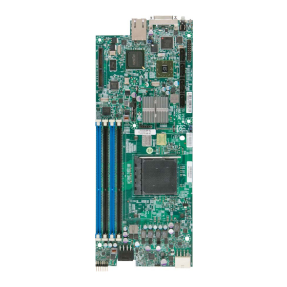
Super Micro Computer, Inc. 980 Rock Ave. San Jose, CA 95131 U.S.A. Tel: +1 (408) 503-8000 Fax: +1 (408) 503-8008 Email: marketing@supermicro.com (General Information) support@supermicro.com (Technical Support) Web Site: www.supermicro.com Europe Address: Super Micro Computer B.V. Het Sterrenbeeld 28, 5215 ML... - Page 9 Chapter 1: Introduction Figure 1-1. H8SME-F Image...
- Page 10 H8SME-F SERVERBOARD USER'S MANUAL Figure 1-2. H8SME-F Motherboard Layout (not drawn to scale) JKVM1 JPB1 JBT1 JSD1 LED3 Winbond WPCM450 SP5100 SR5650 CPU1 JPWR1 Notes: Jumpers not indicated are for test purposes only. Not all ports, jumpers or LED Indicators are available on all serverboards.
- Page 11 Chapter 1: Introduction H8SME-F Quick Reference Jumper Description Default Setting JBT1 CMOS Clear (See Section 2-7) JPB1 BMC Enable/Disable Pins 1-2 (Enabled) JWD1 Watch Dog Pins 1-2 (Reset) Description Dedicated IPMI LAN LEDs LEDs for the dedicated IPMI LAN Ethernet port LED2 LED for Overheat, Power and Fan Fail LED3...
-
Page 12: Motherboard Features
H8SME-F SERVERBOARD USER'S MANUAL Motherboard Features • One AMD Opteron 3000 series (AMD Socket AM3+ type) processors Memory • The H8SME-F motherboard contains four (4) single/dual channel DIMM slots supporting up to 32 GB of Unbuffered ECC/non-ECC DDR3-1600/1333/1066 Mhz speed, very low profi le (VLP) 1 GB, 2 GB, 4 GB or 8 GB size SDRAM memory. Note: Refer to Section 2-5 before installing memory and our web site for recommended DIMMs. - Page 13 Chapter 1: Introduction Onboard I/O • Four (4) SATA ports supported by an on-chip SATA controller (RAID 0, 1 and 10 supported) • One (1) dedicated IPMI LAN port • One (1) JKVM1 keyboard, video, mouse backpanel connector (video supported by Matrox G200eW chip with 16MB DDR2 memory) Other •...
- Page 14 H8SME-F SERVERBOARD USER'S MANUAL Figure 1-3. H8SME-F Motherboard Layout (not drawn to scale) UDIMM/1600 1B AM3R2 UDIMM/1600 1A UDIMM/1600 2B UDIMM/1600 2A HT3 Link 16/16-2.6 GHz PCI-E GEN2 X8 LP PCIE SLOT X8 SR5650 RMII COM1 Clock Gen A-Link DDR2 SDRAM 64MB X16 SATA x4 BMC/VGA...
-
Page 15: Chipset Overview
Chapter 1: Introduction Chipset Overview The H8SME-F motherboard is based on the one AMD SR5650 and one SP5100 chipsets. These chipset functions as a Media and Communications Processors (MCP). Controllers for the system memory are integrated directly into AMD Opteron processors. -
Page 16: Power Confi Guration Settings
H8SME-F SERVERBOARD USER'S MANUAL CPU Overheat/Fan Fail LED and Control This feature is available when the user enables the CPU overheat/Fan Fail warning function in the BIOS. This allows the user to defi ne an overheat temperature. When this temperature is exceeded or when a fan failure occurs, the Overheat/Fan Fail warning LED is triggered. -
Page 17: Power Supply
Chapter 1: Introduction Power Supply As with all computer products, a stable power source is necessary for proper and reliable operation. It is even more important for processors that have high CPU clock rates. The H8SME-F motherboard requires the use of proprietary power supplies. Please refer to the pinout information for the power connectors in Section 8 of Chapter 2 for detailed information on power requirements. - Page 18 H8SME-F SERVERBOARD USER'S MANUAL Notes 1-12...
-
Page 19: Chapter 2 Installation
The following statements are industry standard warnings, provided to warn the user of situations which have the potential for bodily injury. Should you have questions or experience difficulty, contact Supermicro's Technical Support department for assistance. Only certifi ed technicians should attempt to install or confi gure components. - Page 20 H8SME-F SERVERBOARD USER'S MANUAL Warnung Bei Einsetzen einer falschen Batterie besteht Explosionsgefahr. Ersetzen Sie die Batterie nur durch den gleichen oder vom Hersteller empfohlenen Batterietyp. Entsorgen Sie die benutzten Batterien nach den Anweisungen des Herstellers. Attention Danger d'explosion si la pile n'est pas remplacée correctement. Ne la remplacer que par une pile de type semblable ou équivalent, recommandée par le fabricant.
- Page 21 Chapter 2: Installation Product Disposal Warning! Ultimate disposal of this product should be handled according to all national laws and regulations. 製品の廃棄 この製品を廃棄処分する場合、 国の関係する全ての法律 ・ 条例に従い処理する必要が あります。 警告 本产品的废弃处理应根据所有国家的法律和规章进行。 警告 本產品的廢棄處理應根據所有國家的法律和規章進行。 Warnung Die Entsorgung dieses Produkts sollte gemäß allen Bestimmungen und Gesetzen des Landes erfolgen.
-
Page 22: Static-Sensitive Devices
H8SME-F SERVERBOARD USER'S MANUAL Static-Sensitive Devices Electrostatic Discharge (ESD) can damage electronic com ponents. To prevent damage to your system board, it is important to handle it very carefully. The following measures are generally suffi cient to protect your equipment from ESD. Precautions •... -
Page 23: Processor And Heatsink Installation
Chapter 2: Installation Processor and Heatsink Installation Caution: Exercise extreme caution when handling and installing the processor. Always connect the power cord last and always remove it before adding, removing or changing any hardware components. Installation Procedure Follow the procedures as listed below to install the motherboard into a chassis. 1. - Page 24 Installing the Heatsinks We recommend the use of Supermicro 12-node MicroCloud CPU heatsink (SNK- P0047PSR) for the H8SME-F. 1. Place the heatsink on top of the CPU so that the four mounting holes are aligned with those on the motherboard and the heatsink bracket underneath.
-
Page 25: Mounting The Motherboard Into A Chassis
Chapter 2: Installation Mounting the Motherboard into a Chassis All motherboards have standard mounting holes to fi t different types of chassis. Make sure that the locations of all the mounting holes for both the motherboard and the chassis match. Although a chassis may have both plastic and metal mounting fasteners, metal ones are highly recommended because they ground the motherboard to the chassis. -
Page 26: Mounting The Motherboard
H8SME-F SERVERBOARD USER'S MANUAL Mounting the Motherboard Mounting the Motherboard onto the Tray in the Chassis 1. Locate the mounting holes on the motherboard. Refer to the layout on the previous page for mounting hole locations. 2. Locate the matching mounting holes on the motherboard mounting tray. Install standoffs needed. -
Page 27: Motherboard Installed In Tray And Chassis
Chapter 2: Installation Motherboard Installed in Tray and Chassis The image above shows the H8SME-Fmotherboard mounted on a tray to be installed in the Supermicro CSE-939H-R1K63B 3U chassis. The image above shows the server chassis with 12 nodes. -
Page 28: Installing Memory
H8SME-F SERVERBOARD USER'S MANUAL Installing Memory Warning: Exercise extreme caution when installing or removing memory modules to prevent any possible damage. Installing Memory 1. Insert each memory module vertically into its slot, paying attention to the notch along the bottom of the module to prevent inserting the module incorrectly (see Figure 2-1). -
Page 29: Dimm Module Population Confi Guration
Chapter 2: Installation Figure 2-1. DIMM Installation To Install: Insert module Notch Notch vertically and press down until it snaps into place. P a y a t t e n t i o n t o t h e alignment notch at the Front View bottom. -
Page 30: Pci Expansion Cards
H8SME-F SERVERBOARD USER'S MANUAL PCI Expansion Cards A riser card is used to support one Micro-LP (low profi le) PCI-E 2.0 x8 expansion card. Installing a MicroLP Expansion Card 1. Power-down the node using that node's individual power button and remove it from the system. -
Page 31: I/O Port And Control Panel Connections
Chapter 2: Installation I/O Port and Control Panel Connections The I/O ports are color coded in conformance with the PC99 specifi cation to make setting up your system easier. See Figure 2-2 below for the colors and locations of the various I/O ports. Figure 2-2. -
Page 32: Connector Defi Nitions
H8SME-F SERVERBOARD USER'S MANUAL Connector Defi nitions IF + POWER This edge connector, located on the opposite end of the motherboard from the I/O back panel, is used to connect the motherboard to the back plane of the server chassis. Through this connector, the motherboard receives its power and communicates with other components installed in the system. -
Page 33: Trusted Platform Module Header
Chapter 2: Installation Trusted Platform Module Header Trusted Platform Module Header Pin Defi nitions (JTPM1) The JTPM1 header is used to connect Pin# Defi nition Pin# Defi nition a Trusted Platform Module (TPM), LCLK available separately from a third-party vendor. A TPM is a security device that LFRAME No Pin allows encryption and authentication of... -
Page 34: Jumper Settings
H8SME-F SERVERBOARD USER'S MANUAL Jumper Settings Connector Pins Explanation of Jumpers To modify the operation of the motherboard, Jumper jumpers can be used to choose between optional settings. Jumpers create shorts between two pins to change the function Setting of the connector. Pin 1 is identifi ed with a square solder pad on the printed circuit board. -
Page 35: Watch Dog Enable/Disable
Chapter 2: Installation Watch Dog Enable/Disable Watch Dog Jumper Settings (JWD1) JWD1 enables the Watch Dog function, Jumper Setting Defi nition a system monitor that takes action Pins 1-2 Reset when a software application freezes the system. Jumping pins 1-2 will have Pins 2-3 WD reboot the system if a program Open... -
Page 36: 2-10 Onboard Indicators
H8SME-F SERVERBOARD USER'S MANUAL 2-10 Onboard Indicators Dedicated IPMI LAN LEDs IPMI LAN Link LED (Left) & Activity LED (Right) A dedicated IPMI LAN is also included Color Status Defi nition on the H8SME-F serverboards. The Green: Link 100 Mb/s amber LED on the right indicates Solid (Left) -
Page 37: 2-12 Enabling Sata Raid
OS installation. Building a Driver Diskette You must fi rst build a driver diskette from Supermicro drivers for your system. Drivers can be found at ftp://ftp.supermicro.com. (You will have to create this disk on a computer that is already running and with the OS installed.) Building a Driver Diskette 1. -
Page 38: Enabling Sata Raid In The Bios
H8SME-F SERVERBOARD USER'S MANUAL Enabling SATA RAID in the BIOS Before installing the Windows operating system, you must change some settings in the BIOS. Boot up the system and hit the <Delete> key to enter the BIOS Setup Utlility. After the setup utility loads, 1. - Page 39 Chapter 2: Installation Figure 2-4. DotHill RAID Utility Program Screen Figure 2-5. Adaptec RAID Utility Program Screen 2-21...
-
Page 40: Using The Dothill And Adaptec Raid Utility
H8SME-F SERVERBOARD USER'S MANUAL Using the DotHill and Adaptec RAID Utility The RAID Utility program allows you to defi ne the drives you want to include in the RAID array and the mode and type of RAID. Installing the RAID Driver During OS Installation You may also use the procedure below to install the RAID driver during the Windows OS installation: 1. -
Page 41: 2-12 Installing Drivers
The Supermicro Website contains drivers and utilities for your system at ftp://ftp. supermicro.com, some of which must be installed, such as the chipset driver. After downloading and installing the drivers and utilities, the display shown in Figure 2-6 should appear. -
Page 42: Superdoctor Iii
H8SME-F SERVERBOARD USER'S MANUAL SuperDoctor III The SuperDoctor® III program is a Web base management tool that supports remote management capability. It includes Remote and Local Management tools. The local management is called SD III Client. The SuperDoctor III program included on the CD-ROM that came with your motherboard allows you to monitor the environment and operations of your system. - Page 43 Chapter 2: Installation Figure 2-8. SuperDoctor III Interface Display Screen (Remote Control) Note: The SuperDoctor III program and User’s Manual can be downloaded from the Supermicro web site at http://www.supermicro.com/products/accessories/software/ SuperDoctorIII.cfm.For Linux, we recommend that you use the SuperoDoctor II application instead.
-
Page 44: 2-13 Motherboard Battery
H8SME-F SERVERBOARD USER'S MANUAL 2-13 Motherboard Battery Caution: There is a danger of explosion if the onboard battery is installed upside down, which will reverse its polarites (see Figure 2-9). This battery must be replaced only with the same or an equivalent type recommended by the manufacturer (CR2032). -
Page 45: Chapter 3 Troubleshooting
Chapter 3: Troubleshooting Chapter 3 Troubleshooting Troubleshooting Procedures Use the following procedures to troubleshoot your system. If you have followed all of the procedures below and still need assistance, refer to the ‘Technical Support Procedures’ and/or ‘Returning Merchandise for Service’ section(s) in this chapter. Always disconnect the AC power cord before adding, changing or installing any hardware components. -
Page 46: No Video
H8SME-F SERVERBOARD USER'S MANUAL No Video If the power is on but you have no video, remove all the add-on cards and cables. Note: If you are a system integrator, VAR or OEM, a POST diagnostics card is recommended. For I/O port 80h codes, refer to Appendix A. Memory Errors 1. -
Page 47: Frequently Asked Questions
Chapter 3: Troubleshooting 3. If you still cannot resolve the problem, include the following information when contacting us for technical support: • Motherboard model and PCB revision number • BIOS release date/version (this can be seen on the initial display when your system fi... -
Page 48: Returning Merchandise For Service
H8SME-F SERVERBOARD USER'S MANUAL applications you need. Applications on the CD include chipset drivers for Windows and security and audio drivers. Question: Why can't I turn off the power using the momentary power on/off switch? Answer: The instant power off function is controlled in BIOS by the Power Button Mode setting. -
Page 49: Chapter 4 Bios
Chapter 4: BIOS Chapter 4 BIOS Introduction This chapter describes the AMIBIOS™ Setup utility for the H8SME-F motherboard. The 16 Mb AMI BIOS® is stored in a fl ash chip and can be easily upgraded using a fl oppy disk-based program. Note: Due to periodic changes to the BIOS, some settings may have been added or deleted and might not yet be recorded in this manual. -
Page 50: Main Menu
H8SME-F SERVERBOARD USER'S MANUAL Main Menu Figure 4-1: Main BIOS Screen When you fi rst enter AMI BIOS Setup Utility, you will see the Main Menu screen. You can always return to the Main Menu by selecting the Main tab on the top of the screen with the arrow keys. -
Page 51: Advanced Settings Menu
Chapter 4: BIOS Advanced Settings Menu Boot Feature Quick Boot If Enabled, this option will skip certain tests during POST to reduce the time needed for the system to boot up. The options are Enabled and Disabled. Quiet Boot If Disabled, normal POST messages will be displayed on boot-up. - Page 52 H8SME-F SERVERBOARD USER'S MANUAL Power Button Function This sets the function of the power button when you turn off the system. Options include 4-second Overide and Instant Off. Restore on AC Power Loss This sets the action that occurs when an AC power loss occurs. Options include Power Off, Power On and Last State.
- Page 53 Chapter 4: BIOS Power Cap This option can decide the highest P-state in the OS. Options include P-state 0 through P-state 4. HPC Mode This option Enables or Disables support for P-state HPC mode. CPB Mode This option specifi es the method of core performance boost environment. Options include Disabled and Auto.
- Page 54 H8SME-F SERVERBOARD USER'S MANUAL Memory Confi guration Bank Interleaving Select Auto to automatically enable a bank-interleaving memory scheme when this function is supported by the processor. The options are Auto and Disabled. Node Interleaving This option allows you to enable Node Interleaving in the system. Options include Auto and Disabled.
- Page 55 Chapter 4: BIOS Memory Timing Confi guration Memory Timing Confi g This option allows you to set the DRAM timing confi guration for the system. Options include Auto or Manual. Memory Clock Speed This options is only confi gurable if Memory Timing Confi g is set to Manual.
- Page 56 H8SME-F SERVERBOARD USER'S MANUAL IDE Confi guration Onboard PCI IDE Controller This setting allows you to Enable or Disable the PCI IDE controller. OnChip SATA Channel This setting allows you to Enable or Disable the OnChip SATA channel. OnChip SATA Type Use this setting to set the OnChip SATA type.
- Page 57 Chapter 4: BIOS The options are Auto, 0, 1, 2, 3, and 4. Select Auto to allow BIOS to auto detect the PIO mode. Use this value if the IDE disk drive support cannot be determined. Select 0 to allow BIOS to use PIO mode 0, which has a data transfer rate of 3.3 MBs.
- Page 58 H8SME-F SERVERBOARD USER'S MANUAL PCI/PnP Confi guration Clear NVRAM Select Yes to clear NVRAM during boot-up. The options are Yes and No. Plug & Play O/S Select Yes to allow the OS to confi gure Plug & Play devices. (This is not required for system boot if your system has an OS that supports Plug &...
- Page 59 Chapter 4: BIOS Serial 2 Address This option specifi es the base I/O port address and Interrupt Request address of serial port 2. Select "Disabled" to prevent the serial port from accessing any system resources. When this option is set to "Disabled", the serial port physically becomes unavailable.
- Page 60 H8SME-F SERVERBOARD USER'S MANUAL VT-UTF8 Combo Key Support Allows you to Enable or Disable VT-UTF8 combination key support for ANSI/ VT100 terminals. Sredir Memory Display Delay Use this setting to set the delay in seconds to display memory information. Options are No Delay, 1 sec, 2 secs and 4 secs. ...
- Page 61 Chapter 4: BIOS CPU Overheating Alarm (COA) CPU Overheating Alarm (COA) has “Early Alarm” and “Default Alarm” (default) options in the BIOS, and is required to be implemented in all fan speed control modes. Early Alarm is enabled when the Tctl value = 65, and is disabled when the Tctl value drops from 65 to 62.
- Page 62 H8SME-F SERVERBOARD USER'S MANUAL ACPI Confi guration PS2 KB/MS Wakeup This setting allows you to Enable or Disable PS2 keyboard and mouse wakeup. ACPI Aware O/S This setting Enables or Disables ACPI support for the system's operating system. Options include Yes (enabled) or No (disabled). ACPI APIC Support Determines whether to include the ACPI APIC table pointer in the RSDT pointer list.
- Page 63 Chapter 4: BIOS Set LAN Confi guration Use the "+" and "-" keys to choose the desired channel number. This displays Channel Number and Channel Number Status information. This menu contains options for inputing settings for the SET LAN Confi guration Command.
-
Page 64: Security Menu
H8SME-F SERVERBOARD USER'S MANUAL Event Log Confi guration View Event Log Pressing the Enter key will open the event log. Use the "" and "" keys to navigate through the system event log. Mark All Events as Read Selecting this and pressing the Enter key marks all events as read in the event log. -
Page 65: Boot Menu
Chapter 4: BIOS Boot Menu The Boot Menu is accessible only when the "Load Onboard LAN Option ROM" setting (in the PCI/PnP Confi guration menu) is enabled. Boot Device Priority This feature allows you to prioritize the boot sequence from the list of available devices. -
Page 66: Exit Menu
H8SME-F SERVERBOARD USER'S MANUAL Retry Boot Devices This option allows you to retry boot devices. Options include Enabled and Disabled. Exit Menu Select the Exit tab from AMI BIOS Setup Utility screen to enter the Exit BIOS Setup screen. Save Changes and Exit When you have completed the system confi... -
Page 67: Appendix A Bios Post Checkpoint Codes
Appendix A: BIOS POST Checkpoint Codes Appendix A BIOS POST Checkpoint Codes When AMIBIOS performs the Power On Self Test, it writes checkpoint codes to I/O port 0080h. If the computer cannot complete the boot process, diagnostic equipment can be attached to the computer to read I/O port 0080h. A-1 Uncompressed Initialization Codes The uncompressed initialization checkpoint codes are listed in order of execution: Checkpoint... -
Page 68: A-2 Bootblock Recovery Codes
H8SME-F Motherboard User’s Manual A-2 Bootblock Recovery Codes The bootblock recovery checkpoint codes are listed in order of execution: Checkpoint Code Description The onboard fl oppy controller if available is initialized. Next, beginning the base 512 KB memory test. Initializing the interrupt vector table next. Initializing the DMA and Interrupt controllers next. -
Page 69: A-3 Uncompressed Initialization Codes
Appendix A: BIOS POST Checkpoint Codes A-3 Uncompressed Initialization Codes The following runtime checkpoint codes are listed in order of execution. These codes are uncompressed in F0000h shadow RAM. Checkpoint Code Description The NMI is disabled. Next, checking for a soft reset or a power on condition. The BIOS stack has been built. - Page 70 H8SME-F Motherboard User’s Manual Checkpoint Code Description Completed post-video ROM test processing. If the EGA/VGA controller is not found, performing the display memory read/write test next. The EGA/VGA controller was not found. The display memory read/write test is about to begin. The display memory read/write test passed.
- Page 71 Appendix A: BIOS POST Checkpoint Codes Checkpoint Code Description Shutdown was successful. The CPU is in real mode. Disabling the Gate A20 line, parity, and the NMI next. The A20 address line, parity, and the NMI are disabled. Adjusting the memory size depending on relocation and shadowing next.
- Page 72 H8SME-F Motherboard User’s Manual Checkpoint Code Description Any initialization required after the option ROM test has completed. Confi guring the timer data area and printer base address next. Set the timer and printer base addresses. Setting the RS-232 base address next. Returned after setting the RS-232 base address.
Need help?
Do you have a question about the Supero H8SME-F and is the answer not in the manual?
Questions and answers